The document provides information about internal combustion engines. It discusses:
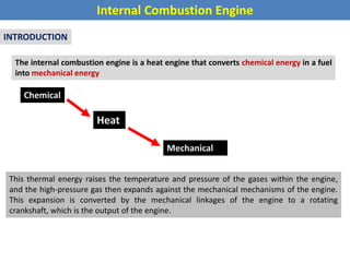
- The basic operation of internal combustion engines, which convert chemical energy from fuel into mechanical energy through a combustion process within the engine.
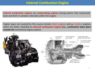
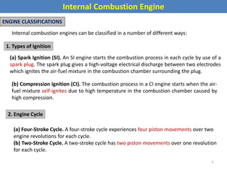
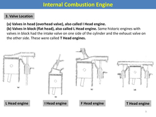
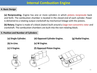
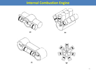
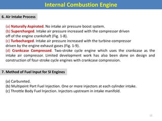
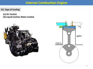
- The different types of internal combustion engines including classifications based on ignition type, engine cycle, valve location, design, cylinder positioning, air intake process, fuel input, fuel used, application, and cooling type.
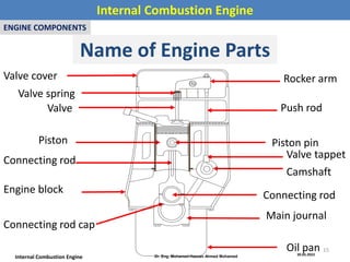
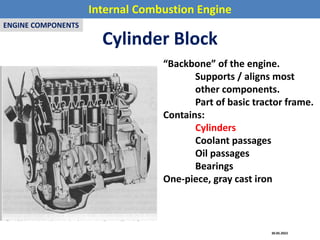
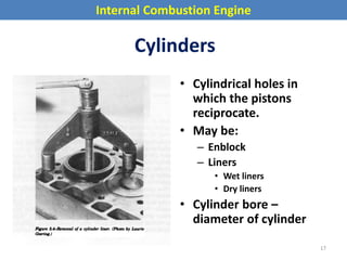
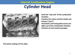
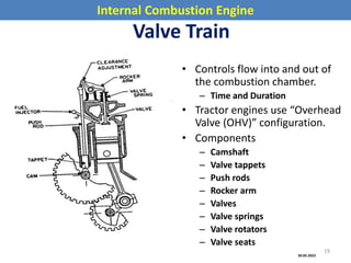
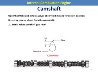
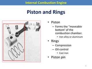
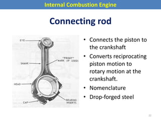
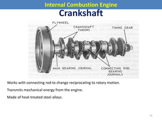
- The key components of internal combustion engines like the cylinder block, cylinders, cylinder head, valve train, pistons, connecting rods, and crankshaft.
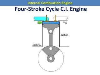
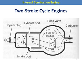
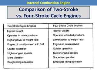
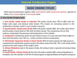
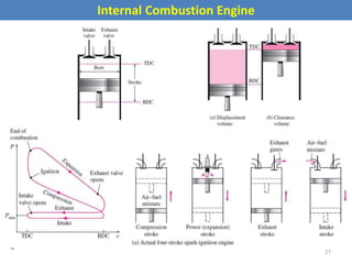
- The basic four-stroke and two-stroke engine cycles for spark ignition and compression ignition engines.


![SBP- IC Engines [Compatibility Mode] (1).pdf](https://cdn.slidesharecdn.com/ss_thumbnails/sbp-icenginescompatibilitymode1-241227102120-3fc3e41a-thumbnail.jpg?width=640&height=640&fit=bounds)


