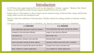
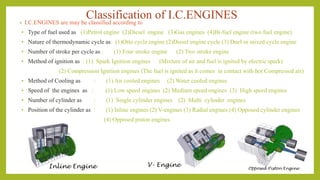
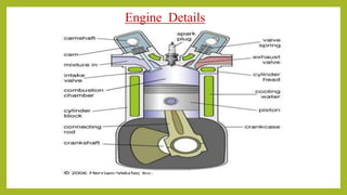
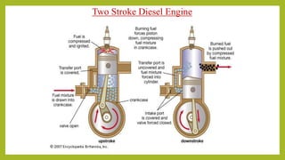
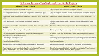
Do you know what is engine, how many types of engines are available now. How conversion of energy takes place from chemical energy to mechanical energy or useful work. Here engine classified according to their combustion, working stroke, arrangement of piston, fuel used for combustion and on the basis of ignition system. 4-stroke petrol engine and 4-stroke diesel engine are described briefly with all 4-strokes which are completed during power conversion process. 2-stroke engine or scooter engine is also described briefly with the complete details of combustion, charge( petrol,diesel ) filling process and how all 4 stroke process(suction, combustion,power stroke, exhaust) completed in 2 stroke engine.
This slides are about inline injection pump and calibration of the pumps .The working of the pump is described in simple words and with examples of daily usable devices.
Engine, classification of heat engine, classification of IC engine, component of IC engine, four stroke engine and 2- stroke engine, petrol and diesel engine, comparisons, terminology related to engine
Er. Uttam Raj Timilsina(MSc.Engineering,IIT Roorkee)
Professor of Agricultural Engineering,Agriculture and Forestry University (AFU), Rampur, Chitwan, Nepal
uttamrajtimilsina@gmail.com
*All Right Reserved**
Uploaded and Shared by AgriYouthNepal
Saudi Arabia stands as a titan in the global energy landscape, renowned for its abundant oil and gas resources. It's the largest exporter of petroleum and holds some of the world's most significant reserves. Let's delve into the top 10 oil and gas projects shaping Saudi Arabia's energy future in 2024.
Hierarchical Digital Twin of a Naval Power SystemKerry Sado
A hierarchical digital twin of a Naval DC power system has been developed and experimentally verified. Similar to other state-of-the-art digital twins, this technology creates a digital replica of the physical system executed in real-time or faster, which can modify hardware controls. However, its advantage stems from distributing computational efforts by utilizing a hierarchical structure composed of lower-level digital twin blocks and a higher-level system digital twin. Each digital twin block is associated with a physical subsystem of the hardware and communicates with a singular system digital twin, which creates a system-level response. By extracting information from each level of the hierarchy, power system controls of the hardware were reconfigured autonomously. This hierarchical digital twin development offers several advantages over other digital twins, particularly in the field of naval power systems. The hierarchical structure allows for greater computational efficiency and scalability while the ability to autonomously reconfigure hardware controls offers increased flexibility and responsiveness. The hierarchical decomposition and models utilized were well aligned with the physical twin, as indicated by the maximum deviations between the developed digital twin hierarchy and the hardware.
Overview of the fundamental roles in Hydropower generation and the components involved in wider Electrical Engineering.
This paper presents the design and construction of hydroelectric dams from the hydrologist’s survey of the valley before construction, all aspects and involved disciplines, fluid dynamics, structural engineering, generation and mains frequency regulation to the very transmission of power through the network in the United Kingdom.
Author: Robbie Edward Sayers
Collaborators and co editors: Charlie Sims and Connor Healey.
(C) 2024 Robbie E. Sayers
Student information management system project report ii.pdfKamal Acharya
Our project explains about the student management. This project mainly explains the various actions related to student details. This project shows some ease in adding, editing and deleting the student details. It also provides a less time consuming process for viewing, adding, editing and deleting the marks of the students.
CFD Simulation of By-pass Flow in a HRSG module by R&R Consult.pptxR&R Consult
CFD analysis is incredibly effective at solving mysteries and improving the performance of complex systems!
Here's a great example: At a large natural gas-fired power plant, where they use waste heat to generate steam and energy, they were puzzled that their boiler wasn't producing as much steam as expected.
R&R and Tetra Engineering Group Inc. were asked to solve the issue with reduced steam production.
An inspection had shown that a significant amount of hot flue gas was bypassing the boiler tubes, where the heat was supposed to be transferred.
R&R Consult conducted a CFD analysis, which revealed that 6.3% of the flue gas was bypassing the boiler tubes without transferring heat. The analysis also showed that the flue gas was instead being directed along the sides of the boiler and between the modules that were supposed to capture the heat. This was the cause of the reduced performance.
Based on our results, Tetra Engineering installed covering plates to reduce the bypass flow. This improved the boiler's performance and increased electricity production.
It is always satisfying when we can help solve complex challenges like this. Do your systems also need a check-up or optimization? Give us a call!
Work done in cooperation with James Malloy and David Moelling from Tetra Engineering.
More examples of our work https://www.r-r-consult.dk/en/cases-en/
Cosmetic shop management system project report.pdfKamal Acharya
Buying new cosmetic products is difficult. It can even be scary for those who have sensitive skin and are prone to skin trouble. The information needed to alleviate this problem is on the back of each product, but it's thought to interpret those ingredient lists unless you have a background in chemistry.
Instead of buying and hoping for the best, we can use data science to help us predict which products may be good fits for us. It includes various function programs to do the above mentioned tasks.
Data file handling has been effectively used in the program.
The automated cosmetic shop management system should deal with the automation of general workflow and administration process of the shop. The main processes of the system focus on customer's request where the system is able to search the most appropriate products and deliver it to the customers. It should help the employees to quickly identify the list of cosmetic product that have reached the minimum quantity and also keep a track of expired date for each cosmetic product. It should help the employees to find the rack number in which the product is placed.It is also Faster and more efficient way.
Industrial Training at Shahjalal Fertilizer Company Limited (SFCL)MdTanvirMahtab2
This presentation is about the working procedure of Shahjalal Fertilizer Company Limited (SFCL). A Govt. owned Company of Bangladesh Chemical Industries Corporation under Ministry of Industries.
Sachpazis:Terzaghi Bearing Capacity Estimation in simple terms with Calculati...Dr.Costas Sachpazis
Terzaghi's soil bearing capacity theory, developed by Karl Terzaghi, is a fundamental principle in geotechnical engineering used to determine the bearing capacity of shallow foundations. This theory provides a method to calculate the ultimate bearing capacity of soil, which is the maximum load per unit area that the soil can support without undergoing shear failure. The Calculation HTML Code included.
Immunizing Image Classifiers Against Localized Adversary Attacksgerogepatton
This paper addresses the vulnerability of deep learning models, particularly convolutional neural networks
(CNN)s, to adversarial attacks and presents a proactive training technique designed to counter them. We
introduce a novel volumization algorithm, which transforms 2D images into 3D volumetric representations.
When combined with 3D convolution and deep curriculum learning optimization (CLO), itsignificantly improves
the immunity of models against localized universal attacks by up to 40%. We evaluate our proposed approach
using contemporary CNN architectures and the modified Canadian Institute for Advanced Research (CIFAR-10
and CIFAR-100) and ImageNet Large Scale Visual Recognition Challenge (ILSVRC12) datasets, showcasing
accuracy improvements over previous techniques. The results indicate that the combination of the volumetric
input and curriculum learning holds significant promise for mitigating adversarial attacks without necessitating
adversary training.
Immunizing Image Classifiers Against Localized Adversary Attacks
Basic of engine
1. INTERNAL COMBUSTION ENGINE
• Introduction
• Terminology
• Otto & Diesel Cycles
• Four stroke Vs Two stroke
• Efficiency
• Fuel and Lubricants
• Fuel Estimation
• Marine IC Engine
By
Sri Ram Kumar KIndian Maritime University - Cochin Campus
2. Introduction
• In 1876 four stroke engine based on Otto cycle was developed by a German engineer Nikolous Otto. Diesel
Engine was developed by another German engineer Rudolf Diesel in the year 1892.
• Engine refers as “Heat engine is a device which converts chemical energy of fuel into Heat energy and this Heat
energy further convert into mechanical work”.
• Based on where the combustion of fuel take place. Whether outside the working cylinder or inside the working
cylinder
• (a) External combustion engines (E.C.ENGINES), (b) Internal combustion engines (I.C.ENGINES)
3. Classification of I.C.ENGINES• I.C.ENGINES are may be classified according to
• Type of fuel used as (1)Petrol engine (2)Diesel engine (3)Gas engines (4)Bi-fuel engine (two fuel engine)
• Nature of thermodynamic cycle as: (1)Otto cycle engine (2)Diesel engine cycle (3) Duel or mixed cycle engine
• Number of stroke per cycle as : (1) Four stroke engine (2) Two stroke engine
• Method of ignition as : (1) Spark Ignition engines (Mixture of air and fuel is ignited by electric spark)
(2) Compression Ignition engines (The fuel is ignited as it comes in contact with hot Compressed air)
• Method of Cooling as : (1) Air cooled engines (2) Water cooled engines
• Speed of the engines as : (1) Low speed engines (2) Medium speed engines (3) High speed engines
• Number of cylinder as : (1) Single cylinder engines (2) Multi cylinder engines
• Position of the cylinder as : (1) Inline engines (2) V-engines (3) Radial engines (4) Opposed cylinder engines
(4) Opposed piston engines
Inline Engine V- Engine Opposed Piston Engine
6. • A two-stroke, or two-cycle, engine is a type of internal combustion
engine which completes a power cycle with two strokes (up and down
movements) of the piston during only one crankshaft revolution.
• This is in contrast to a "four-stroke engine", which requires four strokes of
the piston to complete a power cycle
7. Otto Four stroke cycle
• The four stroke petrol engines works on the principle of theoretical Otto cycle. Also known as
constant volume cycle. shown in Fig below
• In four stroke Petrol engine the vale operating for inlet is called inlet valve and the valve
operating for exhaust is called Exhaust valve. In Petrol engine SPARK plug fitted at the top of
cylinder head initiates the ignition of the air fuel mixture.
• The piston performs four strokes to complete one working cycle.
• The four different strokes are ; (1) SUCTION STROKE (2) COMPRESSION STROKE
(3) POWER STROKE (4) EXHAUST STROKE.
9. DIESEL FOUR STROKE CYCLE
• The four stroke Diesel Engine works on the principle of Diesel Cycle , also called CONSTANT
PRESSURE HEAT ADDITION PROCESS shown in Fig.
• The four stroke Diesel engine is also consists of SUCTION, COMPRESSION,POWER and
EXHAUST strokes.
• The basic construction of a four stroke diesel engine is same as that of four stroke petrol engine,
except instead of spark plug, a fuel injector is mounted in its place .
12. Difference between Petrol and Diesel Engine
The basic differences between Petrol and Diesel Engine given below
PETROL ENGINE DIESEL ENGINE
Works on Otto cycle . Works on Diesel Cycle .
Petrol is used as fuel . Diesel is used as fuel .
Air and fuel mixture enters in cylinder during suction stroke . Only Air is drawn during the suction stroke .
Low compression ratio ranging from 6 to 10 . High compression ratio ranging from14 to 20 .
The compressed charge is ignited by the spark plug. The fuel injector is used in Diesel engine.
High engine speed of about 3000 RPM . Low to medium engine speed ranging from 500 to 1500 RPM.
TheThermal efficiency is lower due to lower Compression ratio . TheThermal efficiency is higher due to high Compression ratio .
Lighter in weight because maximum pressure andTemperature is
less .
Heavier in Weight because maximum pressure and temperature is
high .
Less Costlier . More Costlier .
Maintenance cost is Less . Maintenance cost is Slightly higher .
Easier starting even in cold weather . Difficult to start in cold weather .
Running cost Higher because petrol is Costlier . Running cost is Less because diesel is Cheaper .
13. Two Stroke Cycle
• As the name itself implies, all the processes in two stroke cycle engine are completed
in two strokes.
• In four stroke engine cycle Two complete revolutions of crank shaft is required for
completing one cycle .
14. Two Stroke Cycle Engines
• In two stroke Engine cycle Operations Suction ,
Compression , Expansion and Exhaust are
completed in One Complete revolution of the
crank shaft in two stroke Engines.
• These engines have one Power stroke per
revolution of the crank shaft.
• In two stroke engines there is two openings called
PORTS are provided in place of valves of four
stroke engines.
• These Ports are opened and closed by
Reciprocating Motion of the Piston in the
Cylinder. One port is known as INLET PORT and
another port is known as EXHAUST PORT .
17. FOUR STROKE ENGINE TWO STROKE ENGINE
Four piston strokes require to complete one cycle . Only two piston strokes required to complete one cycle .
Two complete revolutions of crank shaft is required to complete one cycle. Only one complete revolution of crank shaft is required to complete one cycle .
Equal to half of the speed of engine crank shaft . Number of power stroke/min.
n=N/2
Equal to the speed of engine crank shaft . Number of power stroke/min. n=N
Power is developed in every alternate revolution of crank shaft . Power is also developed in every revolution of crank shaft hence for same
cylinder.
The power is developed in every alternate revolution, hence heavy fly wheel is
required .
The power is developed in every revolution , hence lighter flywheel is required
.
These engines are Heavier, larger and required more space. These engine are lighter more compact and require less space.
The inlet and exhaust valve are require and they are operated by valve
operated by valve operating mechanism.
In place of valve, ports are used which opens and close by motion of piston
itself.
Lubricating oil consumption is less . Lubricating oil consumption is more because lubricating oil is mixed with fuel
Thermal efficiency is higher . Less Thermal efficiency.
Mechanical efficiency is Low because of more number of moving parts . Mechanical efficiency is High because of less number of moving parts .
These Engines are used basically in High Power Application Where more
space is available like Cars , Truck, Tractors , Buses etc .
These Engines are used basically in Low Power Application Where less space
is available like Mopeds ,Scooters ,Motor cycle etc .
Difference Between Two Stroke and Four Stroke Engines
20. Compression ratio (r)
• VC = Clearance volume
• VS = Swept volume = /4 D2 L
where: L (stroke) = 2 ρ, ρ is the crankshaft radius
- Increasing the compression ration increases the
thermal efficiency, compression is limited by the knock
limit.
C
SC
V
VV
r
C
S
V
V
1r
TDCatpistonaboveVolume
BDCatpistonaboveVolume
r
21. 21
Engine Displacement, Swept Volume
or Engine Capacity (Ve):
• Ve = VS n
• Ve = (/4) D2 L n
Where:
Ve = engine capacity, Vs = cylinder swept volume
n = number of cylinders, L = stroke, D = bore diameter
Stroke VS
Bore
VS VS VS
TDC
BDC
23. 23
Volumetric Efficiency V (cont.)
• Engines are only capable of 80% to 90%
volumetric efficiency.
• Volumetric efficiency depends upon throttle
opening and engine speed as well as induction
and exhaust system layout, port size and valve
timing and opening duration.
• High volumetric efficiency increases engine power.
• Turbo charging is capable of increasing volumetric
efficiency up to 50%.
24. 24
Indicated mean effective pressure (imep)
Compression ratio
Air/fuel ratio
Volumetric efficiency
Ignition timing
Valve timing and lift
Air pressure and temperature
25. 25
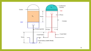
Pressure, Force, Work & Power
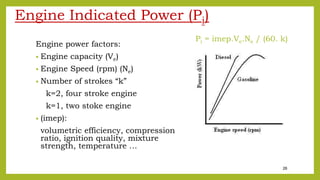
p = imep (N/m2)
A (m2)
F= P.A (N)
L (m)
F (N)
Work (W) = F.L (N m)
Time (t) = 60 / (Ne /k) (s)
Indicated power (Pi) cylinder = W/t = F.L .Ne/(k*60) (W)
(Pi) cylinder = (imep.A.L.Ne) / (k . 60)
(Pi) engine = imep. (A.L.n) Ne / (k . 60)
(Pi) engine = [imep. Ve . Ne/ (k . 60)] (W)
a
b
c
k = 2 (four stroke)
k = 1 (two stoke)
26. 26
Engine Indicated Power (Pi)
Engine power factors:
• Engine capacity (Ve)
• Engine Speed (rpm) (Ne)
• Number of strokes “k”
k=2, four stroke engine
k=1, two stoke engine
• (imep):
volumetric efficiency, compression
ratio, ignition quality, mixture
strength, temperature …
Pi = imep.Ve.Ne / (60. k)
28. 28
Engine Brake Power (Pb)
-This is the power developed at the crankshaft or flywheel.
-The term brake originated from the method used to determine an
engine’s power output by measuring the torque using some form of
friction dynamometer.
29. 29
Engine Mechanical Efficiency m
• Pb = Pi - Pf
Where:
Pi = indicated power
Pb= brake power
Pf = friction power
• m = Pb / Pi
30. 30
Engine Brake Power (Pb)
• Pb = Pi m
• Pb = (imep Ve Ne / 60 k) m
• Pb = (imep m)Ve Ne / 60 k
• Pb = bemp Ve Ne / 60 k
Where:
bmep = brake mean effective pressure
bmep = imep m
* bmep is indication of engine efficiency regardless of
capacity or engine speed, 1000 kPa represent high
efficiency.
31. 31
Gross & Net Brake Power
• Gross brake power is measured
without the following items:
Cooling fan, coolant pump, radiator,
alternator, exhaust system. (SAE)
• Net brake power is measured with all
the above items. (DIN)
• Gross power is 10-15% more than net
power.
32. 32
Engine Torque Te
Torque and crankshaft angle:
Work is also accomplished when
the torque is applied through an
angle.
• Distance xy = rθ
• W = F . xy = F r θ = T θ
• W per one revolution = T (2)
• P = W/t = T (2)/t = Tω/1000
Where: ω = 2 Ne/60
33. 33
Engine Torque Te (Cont.)
• Pb = T ω = Te (2 Ne/60) = Te Ne / 9550 (kW)
• bmep . Ve . Ne / k 60 = Te (2 Ne/60)
• Te = bmep . Ve / 2 . K
Where:
Pe = Engine power (kW)
Ne = Engine speed (rpm)
Te = Engine torque (N m)
bemp = brake mean effective pressure (Pa)
Ve = engine capacity (m3)
k = 2, for 4-stroke engines
1, for 2-stroke engines
34. 34
Engine Torque Te (Cont.)
- There is a direct relationship
between BMEP and torque
output.
- The torque curve with engine
rpm is identical to the bmep
curve, with different values.
35. 35
Engine Fuel consumption (FC)
The amount of fuel an engine consumes can be measured by:
• volume (cm3 or liter) per (sec. or mint, or hr)
or
• mass (kg) per (sec, or mint, or hr).
36. 36
Engine Specific Fuel Consumption (SFC)
• Specific fuel consumption represents the mass or volume of
fuel an engine consumes per hour while it produces 1 kW of
power.
• Typical gasoline engines will have an SFC of about 0.3
kg/(kW.h).
• SFC is an indication of the engine’s thermal or heat efficiency.
• (kg/h)/kW or kg/(kW h)
b
.
P
SFC m
37. 37
Engine Thermal Efficiency (th)
• The efficiency of an engine in converting the heat energy contained
in the liquid fuel into mechanical energy is termed its thermal
efficiency.
• The petrol engine is particularly inefficient and at its best may
reach 25% efficiency.
• The thermal efficiency of a diesel engine can reach 35% due to its
higher compression ratio.
38. 38
Thermal Efficiency (th) (Cont.)
where:
is the fuel consumption (kg/h)
is the fuel consumption (L/h)
CV is the calorific or heat value of 1 kg of the fuel
(kJ/kg or MJ/kg). (CV for gasoline is 40000 kJ/kg)
ρ is the relative density (kg/L) of the fuel.
CV.ρ.
P3600
)(ηefficiencythermalBrake
CV.
.6060.P
)(ηefficiencythermalBrake
V
m
.
b
th
.
b
th
m
.
V
.
39. 39
Specific Fuel Consumption (SFC)
& Thermal efficiency (th)
Where:
th = thermal efficiency
= fuel consumption (kg/h)
Pb = brake power (kW)
CV = calorific value (kJ)
SFC = specific fuel consumption (kg/(kW.h))
CVSFC.
3600
CV.)/P(
3600
CV.
P3600
η
b
..
b
th
mm
m
.
40. 40
Specific Fuel Consumption (SFC)
& Thermal efficiency (th)
• A mirror reflection of the
SFC curve shows the shape
of the engine’s thermal
efficiency curve.
• The lowest point on the SFC
curve becomes the highest
point on the thermal
efficiency curve.
41. 41
Power Units
• BHP (bhp) = 550 ft lb/s
• PS = 75 kg m/s
• kW = 1000 (N m/s)
BHP = British and American “horse power”
PS ="PferdeStärke“ is "horse power“ in
German
• PS = 0.986 bhp, BHP = 1.0142 PS
• kW = 1.36 PS, PS = 0.73529 kW
• kW = 1.341 bhp, BHP = 0.7457 kW
42. 42
Engine Performance Curves
Imep
Bemp and torque
Indicated power
Brake power
Indicated thermal efficiency
Brake thermal efficiency
Specific fuel consumption