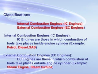
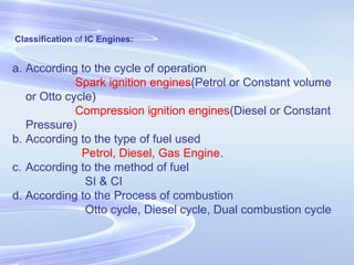
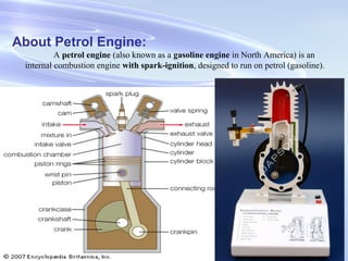
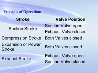
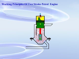
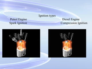
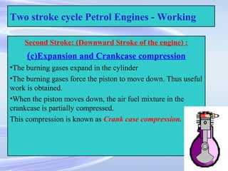
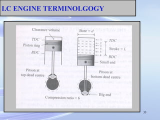
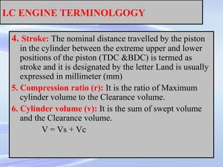
UNIT- I
INTRODUCTION
TO
IC ENGINES
HEAT
HEAT AND WORK
CONVERTIONS
• WORK can be completely converted into
HEAT but HEAT cannot be completely
converted into WORK .
• THE DEVICE WHICH CONVERTS
HEAT INTO WORK IS ENGINE
Classifications:
Internal Combustion Engines (IC Engines)
External Combustion Engines (EC Engines)
Internal Combustion Engines (IC Engines):
IC Engines are those in which combustion of
fuels take places inside engine cylinder (Example:
Petrol, Diesel,GAS)
External Combustion Engines (EC Engines):
EC Engines are those in which combustion of
fuels take places outside engine cylinder (Example:
Steam Engine, Steam turbine)
Classification of IC Engines:
a. According to the cycle of operation
Spark ignition engines(Petrol or Constant volume
or Otto cycle)
Compression ignition engines(Diesel or Constant
Pressure)
b. According to the type of fuel used
Petrol, Diesel, Gas Engine.
c. According to the method of fuel
SI & CI
d. According to the Process of combustion
Otto cycle, Diesel cycle, Dual combustion cycle
Basic Parts of IC Engines:
cylinder,
cylinder head,
piston,
connecting rod,
crankshaft,
flywheel
Camshaft,
crankcase,
piston pin,
crankpin,
piston rings &oil ring
About Petrol Engine:
A petrol engine (also known as a gasoline engine in North America) is an
internal combustion engine with spark-ignition, designed to run on petrol (gasoline).
Working Cycles Four Stroke Petrol Engine:
 It is also known as Otto cycle or constant volume cycle.
 Cycle of operation is completed in 4-strokes of the piston or 2 revolutions of the
crankshaft.
 Each stroke consists of 180°, of crankshaft rotation and hence a cycle consists of 720°of
crankshaft rotation.
2-stroke: 1 power stroke per 1 crankshaft rev
4-stroke: 1 power stroke per 2 crankshaft rev
Principle of Operation:
The series of operations of an ideal four-stroke SI engine are as follows
Suction Stroke or charging stroke
Compression Stroke
Expansion or Power Stroke or working stroke
Exhaust Stroke
Principle of Operation
Principle of Operation:
Stroke Valve Position
Suction Stroke
Suction Valve open
Exhaust Valve closed
Compression Stroke Both Valves closed
Expansion or Power
Stroke
Both Valves closed
Exhaust Stroke
Exhaust Valve open
Suction Valve closed
Suction Compression Ign.-Combn. Expansion Exhaust
FOUR STROKE SI ENGINE
FOUR STROKE ENGINE
Working Principles of Four Stroke Diesel Engine:
Increased pressure of combustion gases acts on piston -> converted
to rotary motion
Can be 2 or 4 stroke engines
2-stroke: 1 power stroke per 1 crankshaft rev
4-stroke: 1 power stroke per 2 crankshaft rev
Engine stroke:
A stroke is a single traverse of the cylinder by the piston (from
TDC to BDC)
1 revolution of crankshaft = 2 strokes of piston
Working Principles of Four-Stroke Diesel Engine
Strokes
Intake
Compression
Power
Exhaust
Working Principles Of Four Stroke Diesel Engine:
Intake stroke
Intake valve open, exhaust valve shut
Piston travels from TDC to BDC
Air drawn in
Compression stroke
Intake and exhaust valves shut
Piston travels from BDC to TDC
Temperature and pressure of air increase
Working Principles Of Four Stroke Diesel Engine:
Power stroke
Intake and exhaust valves shut
Fuel injected into cylinder and ignites
Piston forced from TDC to BDC
Exhaust stroke
Intake valve shut, exhaust valve open
Piston moves from BDC to TDC
Combustion gases expelled
FOUR STROKE CI ENGINE
Working Principles Of Two Stroke Petrol Engine
Ignition types
Petrol Engine Diesel Engine
Spark Ignition Compression Ignition
23
Two Stroke Cycle Petrol Engine -
Construction
Construction :
•A piston reciprocates inside the cylinder
•It is connected to the crankshaft by means of connecting rod and
crank
•There are no valves in two stroke engines, instead of valves ports
are cut on the cylinder walls.
•There are three ports, namely inlet, exhaust and transfer ports.
•The closing and opening of the ports are obtained by the movement of
piston. The crown of piston is made in to a shape to perform this.
•A spark plug is also provided.
24
Two stroke cycle Petrol Engines - Working
First Stroke : (Compression, ignition and inductance)
(Upward stroke of piston)
(a) compression:
• The piston moves up from Bottom Dead Centre (BDC)
to Top Dead Centre (TDC)
• Both transfer and exhaust ports are covered by the
piston.
• Air fuel mixture which is transferred already into the
engine cylinder is compressed by moving piston.
• The pressure and temperature increases
• at the end of compression.
25
Two stroke cycle Petrol Engines - Working
First Stroke : (Compression, ignition and
inductance) (Upward stroke of piston)
(b) Ignition and Inductance:
• Piston almost reaches the top dead centre
•The air fuel mixture inside the cylinder is ignited by means of
an electric spark produced by a spark plug
•At the same time, the inlet port is uncovered by the plane.
•Fresh air fuel mixture enters the crankcase through the inlet port
26
Two stroke cycle Petrol Engines - Working
Second Stroke: (Downward Stroke of the engine) :
(c)Expansion and Crankcase compression
•The burning gases expand in the cylinder
•The burning gases force the piston to move down. Thus useful
work is obtained.
•When the piston moves down, the air fuel mixture in the
crankcase is partially compressed.
This compression is known as Crank case compression.
27
Two stroke cycle Petrol Engines - Working
Second Stroke: (Downward Stroke of the engine) :
(d) Exhaust and transfer:
•At the end of expansion, exhaust port is uncovered.
•Burnt gases escape to the atmosphere.
•Transfer port is also opened. The partially compressed air fuel mixture
enters the cylinder through the transfer port.
•The crown of the piston is made of a deflected shape. So the fresh charge
entering the cylinder is deflected upwards in the cylinder.
•Thus the escape of fresh charge along with the exhaust
gases is reduced.
Compression
Intake and exhaust valves shut
Piston travels from BDC to TDC
Temperature and pressure of air increase
Power stroke
Intake and exhaust valves shut
Fuel injected into cylinder and ignites
Piston forced from TDC to BDC
Working Principles Of Two Stroke Diesel Engine
• Strokes
– Compression
– Power
– (Intake/Exhaust)
Working Principles Of Two Stroke Diesel Engine
Application Of Four stroke Cycle Engine
Used in heavy vehicles
Buses,
Lorries,
Trucks etc.,
Application Of Two stroke Cycle Engine
Used in light vehicles
Bikes,
Scooters,
Mopeds
Ship propulsion
Application Of Four stroke Petrol Engine
Buses ,Trucks
Mobile electric generating sets.
Small pumping sets with side cars
Application Of Four stroke Diesel Engine
30kw-Tractors
40to 100kw – jeeps, buses and trucks
200 to 400kw-Earthmoving m/c
100 to 35000kw-Marine application
33
I.C ENGINE TERMINOLGOGY
34
I.C ENGINE TERMINOLGOGY
The standard terms used in I.C Engines are
1. Bore: Inside diameter of the cylinder is termed as Bore
and it is designated by the letter d and is usually expressed
in millimeter (mm)
2. Top Dead Center (TDC): The extreme position reached
by the piston at the top of the cylinder in the vertical
engine is called Top Dead center. It is also called the Inner
dead centre (IDC).
3. Bottom Dead Center (BDC): The extreme position
reached by the piston at the Bottom of the cylinder in the
vertical engine is called Bottom Dead center. It is also
called the Outer dead centre (ODC).
35
I.C ENGINE TERMINOLGOGY
4. Stroke: The nominal distance travelled by the piston
in the cylinder between the extreme upper and lower
positions of the piston (TDC &BDC) is termed as
stroke and it is designated by the letter Land is usually
expressed in millimeter (mm)
5. Compression ratio (r): It is the ratio of Maximum
cylinder volume to the Clearance volume.
6. Cylinder volume (v): It is the sum of swept volume
and the Clearance volume.
V = Vs + Vc
36
I.C ENGINE TERMINOLGOGY
• 7. Displacement (or)Swept volume (Vs): It is the
volume of space generated by the movement of
piston from one dead center to another dead center.
It is expressed in terms of cubic centimeter (cc) and
given by
VS = A * L = π * d2
* L / 4
8. Clearance Volume( Vc): It is the space in the
cylinder, when the piston is at Top Dead Center It is
designated as VC and expressed in cubic centimeter
(cc).
Comparison of Petrol and Diesel Engines
Petrol Engines
1. A petrol engine draws a
mixture of petrol and air
during suction stroke.
2. The carburettor is employed to
mix air and petrol in the
required proportion and to
supply it to the engine during
suction stroke.
3. Pressure at the end of
compression is about 10 bar.
4. The charge (i.e. petrol and air
mixture) is ignited with the
help of spark plug.
Diesel Engines
A diesel engine draws only air
during suction stroke.
The injector or atomiser is
employed to inject the fuel at the
end of combustion stroke.
Pressure at the end of
compression is about 35 bar.
The fuel is injected in the form of
fine spray. The temperature of
the compressed air is
sufficiently high to ignite the
fuel.
Comparison of Petrol and Diesel Engines
(contd..)
10. The maintenance cost is less.
11. The thermal efficiency is about
26%.
12. Overheating trouble is more
due to low thermal efficiency.
13. These are high speed engines.
14. The petrol engines are
generally employed in light
duty vehicle such as scooters,
motorcycles and cars. These
are also used in aeroplanes.
The maintenance cost is more.
The thermal efficiency is about
40%.
Overheating trouble is less due
to high thermal efficiency.
These are relatively low speed
engines.
The diesel engines are generally
employed in heavy duty vehicles
like buses, trucks, and earth
moving machines.
ENGINE SPECIFICATIONS
Engine capacity : 177.4cc
Engine type : single cylinder, air cooled 4st
Max Power : 17.3bhp @ 8500rpm
Max Torque : 1.58kgm @ 6500rpm
Gear box : 5 speed constant mesh
Fuel system : carbureted
Front brake : 270mm petal disc brake
Rear brake : 200mm petal disc brake
Front suspension : Telescopic hydraulic fork
Rear suspension : gas shocks
Front tyre: 90/90 x17
Rear tyre : 110/80 x 17
Height : 100mm
Length : 2085mm
Width : 730mm
Ground clearance : 180mm
Kerb weight : 137kg
Fuel tank capacity : 16 liters

Ic engines

  • 1.
  • 2.
  • 3.
  • 4.
    CONVERTIONS • WORK canbe completely converted into HEAT but HEAT cannot be completely converted into WORK . • THE DEVICE WHICH CONVERTS HEAT INTO WORK IS ENGINE
  • 5.
    Classifications: Internal Combustion Engines(IC Engines) External Combustion Engines (EC Engines) Internal Combustion Engines (IC Engines): IC Engines are those in which combustion of fuels take places inside engine cylinder (Example: Petrol, Diesel,GAS) External Combustion Engines (EC Engines): EC Engines are those in which combustion of fuels take places outside engine cylinder (Example: Steam Engine, Steam turbine)
  • 6.
    Classification of ICEngines: a. According to the cycle of operation Spark ignition engines(Petrol or Constant volume or Otto cycle) Compression ignition engines(Diesel or Constant Pressure) b. According to the type of fuel used Petrol, Diesel, Gas Engine. c. According to the method of fuel SI & CI d. According to the Process of combustion Otto cycle, Diesel cycle, Dual combustion cycle
  • 7.
    Basic Parts ofIC Engines: cylinder, cylinder head, piston, connecting rod, crankshaft, flywheel Camshaft, crankcase, piston pin, crankpin, piston rings &oil ring
  • 8.
    About Petrol Engine: Apetrol engine (also known as a gasoline engine in North America) is an internal combustion engine with spark-ignition, designed to run on petrol (gasoline).
  • 9.
    Working Cycles FourStroke Petrol Engine:  It is also known as Otto cycle or constant volume cycle.  Cycle of operation is completed in 4-strokes of the piston or 2 revolutions of the crankshaft.  Each stroke consists of 180°, of crankshaft rotation and hence a cycle consists of 720°of crankshaft rotation. 2-stroke: 1 power stroke per 1 crankshaft rev 4-stroke: 1 power stroke per 2 crankshaft rev Principle of Operation: The series of operations of an ideal four-stroke SI engine are as follows Suction Stroke or charging stroke Compression Stroke Expansion or Power Stroke or working stroke Exhaust Stroke
  • 10.
  • 11.
    Principle of Operation: StrokeValve Position Suction Stroke Suction Valve open Exhaust Valve closed Compression Stroke Both Valves closed Expansion or Power Stroke Both Valves closed Exhaust Stroke Exhaust Valve open Suction Valve closed
  • 12.
  • 13.
  • 14.
  • 15.
    Working Principles ofFour Stroke Diesel Engine: Increased pressure of combustion gases acts on piston -> converted to rotary motion Can be 2 or 4 stroke engines 2-stroke: 1 power stroke per 1 crankshaft rev 4-stroke: 1 power stroke per 2 crankshaft rev Engine stroke: A stroke is a single traverse of the cylinder by the piston (from TDC to BDC) 1 revolution of crankshaft = 2 strokes of piston
  • 16.
    Working Principles ofFour-Stroke Diesel Engine Strokes Intake Compression Power Exhaust
  • 17.
    Working Principles OfFour Stroke Diesel Engine: Intake stroke Intake valve open, exhaust valve shut Piston travels from TDC to BDC Air drawn in Compression stroke Intake and exhaust valves shut Piston travels from BDC to TDC Temperature and pressure of air increase
  • 18.
    Working Principles OfFour Stroke Diesel Engine: Power stroke Intake and exhaust valves shut Fuel injected into cylinder and ignites Piston forced from TDC to BDC Exhaust stroke Intake valve shut, exhaust valve open Piston moves from BDC to TDC Combustion gases expelled
  • 19.
  • 20.
    Working Principles OfTwo Stroke Petrol Engine
  • 21.
    Working Principles OfTwo Stroke Petrol Engine
  • 22.
    Ignition types Petrol EngineDiesel Engine Spark Ignition Compression Ignition
  • 23.
    23 Two Stroke CyclePetrol Engine - Construction Construction : •A piston reciprocates inside the cylinder •It is connected to the crankshaft by means of connecting rod and crank •There are no valves in two stroke engines, instead of valves ports are cut on the cylinder walls. •There are three ports, namely inlet, exhaust and transfer ports. •The closing and opening of the ports are obtained by the movement of piston. The crown of piston is made in to a shape to perform this. •A spark plug is also provided.
  • 24.
    24 Two stroke cyclePetrol Engines - Working First Stroke : (Compression, ignition and inductance) (Upward stroke of piston) (a) compression: • The piston moves up from Bottom Dead Centre (BDC) to Top Dead Centre (TDC) • Both transfer and exhaust ports are covered by the piston. • Air fuel mixture which is transferred already into the engine cylinder is compressed by moving piston. • The pressure and temperature increases • at the end of compression.
  • 25.
    25 Two stroke cyclePetrol Engines - Working First Stroke : (Compression, ignition and inductance) (Upward stroke of piston) (b) Ignition and Inductance: • Piston almost reaches the top dead centre •The air fuel mixture inside the cylinder is ignited by means of an electric spark produced by a spark plug •At the same time, the inlet port is uncovered by the plane. •Fresh air fuel mixture enters the crankcase through the inlet port
  • 26.
    26 Two stroke cyclePetrol Engines - Working Second Stroke: (Downward Stroke of the engine) : (c)Expansion and Crankcase compression •The burning gases expand in the cylinder •The burning gases force the piston to move down. Thus useful work is obtained. •When the piston moves down, the air fuel mixture in the crankcase is partially compressed. This compression is known as Crank case compression.
  • 27.
    27 Two stroke cyclePetrol Engines - Working Second Stroke: (Downward Stroke of the engine) : (d) Exhaust and transfer: •At the end of expansion, exhaust port is uncovered. •Burnt gases escape to the atmosphere. •Transfer port is also opened. The partially compressed air fuel mixture enters the cylinder through the transfer port. •The crown of the piston is made of a deflected shape. So the fresh charge entering the cylinder is deflected upwards in the cylinder. •Thus the escape of fresh charge along with the exhaust gases is reduced.
  • 28.
    Compression Intake and exhaustvalves shut Piston travels from BDC to TDC Temperature and pressure of air increase Power stroke Intake and exhaust valves shut Fuel injected into cylinder and ignites Piston forced from TDC to BDC Working Principles Of Two Stroke Diesel Engine
  • 29.
    Working Principles OfTwo Stroke Diesel Engine • Strokes – Compression – Power – (Intake/Exhaust)
  • 30.
    Working Principles OfTwo Stroke Diesel Engine
  • 31.
    Application Of Fourstroke Cycle Engine Used in heavy vehicles Buses, Lorries, Trucks etc., Application Of Two stroke Cycle Engine Used in light vehicles Bikes, Scooters, Mopeds Ship propulsion
  • 32.
    Application Of Fourstroke Petrol Engine Buses ,Trucks Mobile electric generating sets. Small pumping sets with side cars Application Of Four stroke Diesel Engine 30kw-Tractors 40to 100kw – jeeps, buses and trucks 200 to 400kw-Earthmoving m/c 100 to 35000kw-Marine application
  • 33.
  • 34.
    34 I.C ENGINE TERMINOLGOGY Thestandard terms used in I.C Engines are 1. Bore: Inside diameter of the cylinder is termed as Bore and it is designated by the letter d and is usually expressed in millimeter (mm) 2. Top Dead Center (TDC): The extreme position reached by the piston at the top of the cylinder in the vertical engine is called Top Dead center. It is also called the Inner dead centre (IDC). 3. Bottom Dead Center (BDC): The extreme position reached by the piston at the Bottom of the cylinder in the vertical engine is called Bottom Dead center. It is also called the Outer dead centre (ODC).
  • 35.
    35 I.C ENGINE TERMINOLGOGY 4.Stroke: The nominal distance travelled by the piston in the cylinder between the extreme upper and lower positions of the piston (TDC &BDC) is termed as stroke and it is designated by the letter Land is usually expressed in millimeter (mm) 5. Compression ratio (r): It is the ratio of Maximum cylinder volume to the Clearance volume. 6. Cylinder volume (v): It is the sum of swept volume and the Clearance volume. V = Vs + Vc
  • 36.
    36 I.C ENGINE TERMINOLGOGY •7. Displacement (or)Swept volume (Vs): It is the volume of space generated by the movement of piston from one dead center to another dead center. It is expressed in terms of cubic centimeter (cc) and given by VS = A * L = π * d2 * L / 4 8. Clearance Volume( Vc): It is the space in the cylinder, when the piston is at Top Dead Center It is designated as VC and expressed in cubic centimeter (cc).
  • 37.
    Comparison of Petroland Diesel Engines Petrol Engines 1. A petrol engine draws a mixture of petrol and air during suction stroke. 2. The carburettor is employed to mix air and petrol in the required proportion and to supply it to the engine during suction stroke. 3. Pressure at the end of compression is about 10 bar. 4. The charge (i.e. petrol and air mixture) is ignited with the help of spark plug. Diesel Engines A diesel engine draws only air during suction stroke. The injector or atomiser is employed to inject the fuel at the end of combustion stroke. Pressure at the end of compression is about 35 bar. The fuel is injected in the form of fine spray. The temperature of the compressed air is sufficiently high to ignite the fuel.
  • 38.
    Comparison of Petroland Diesel Engines (contd..) 10. The maintenance cost is less. 11. The thermal efficiency is about 26%. 12. Overheating trouble is more due to low thermal efficiency. 13. These are high speed engines. 14. The petrol engines are generally employed in light duty vehicle such as scooters, motorcycles and cars. These are also used in aeroplanes. The maintenance cost is more. The thermal efficiency is about 40%. Overheating trouble is less due to high thermal efficiency. These are relatively low speed engines. The diesel engines are generally employed in heavy duty vehicles like buses, trucks, and earth moving machines.
  • 39.
  • 40.
  • 41.
  • 42.
  • 43.
  • 44.
  • 45.
  • 46.
    ENGINE SPECIFICATIONS Engine capacity: 177.4cc Engine type : single cylinder, air cooled 4st Max Power : 17.3bhp @ 8500rpm Max Torque : 1.58kgm @ 6500rpm Gear box : 5 speed constant mesh Fuel system : carbureted Front brake : 270mm petal disc brake Rear brake : 200mm petal disc brake Front suspension : Telescopic hydraulic fork Rear suspension : gas shocks Front tyre: 90/90 x17 Rear tyre : 110/80 x 17 Height : 100mm Length : 2085mm Width : 730mm Ground clearance : 180mm Kerb weight : 137kg Fuel tank capacity : 16 liters