Downloaded 425 times
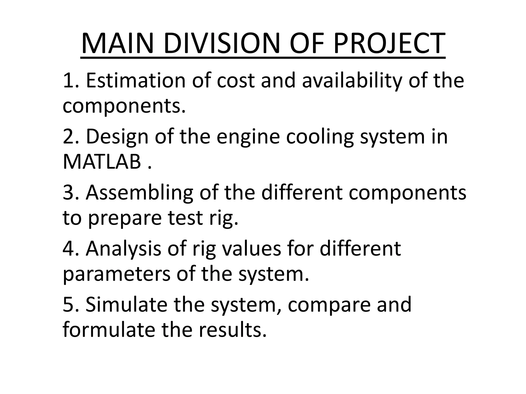
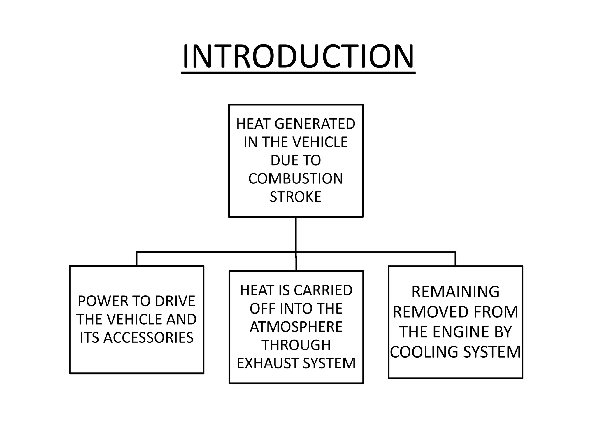
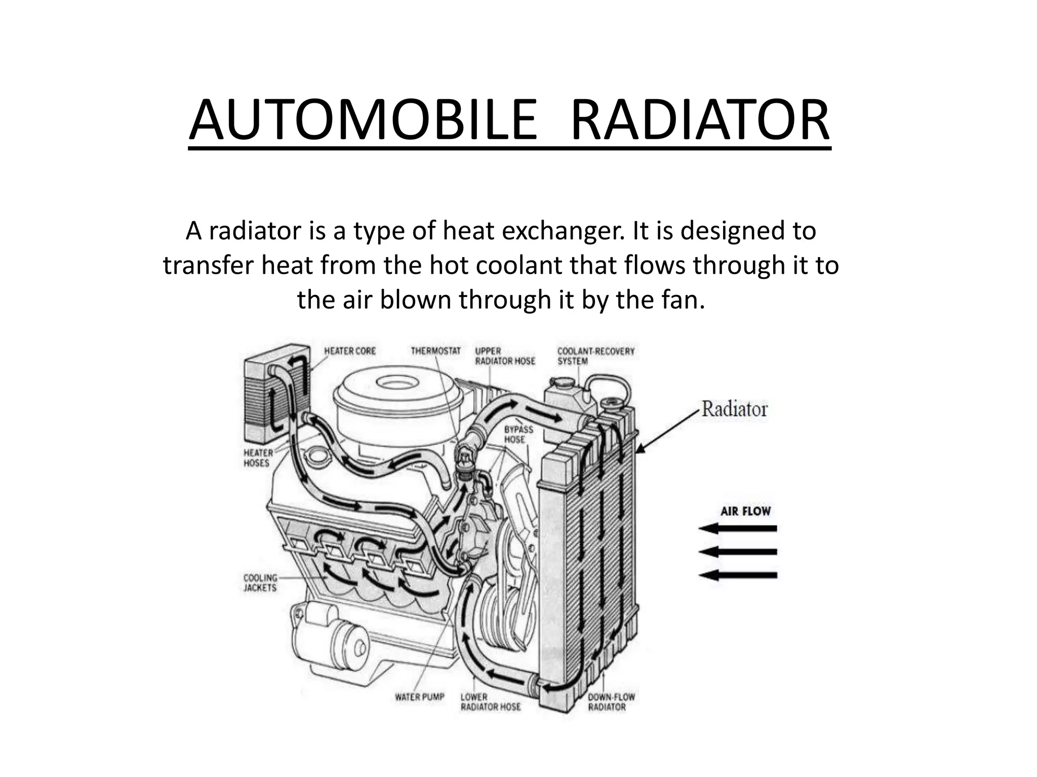
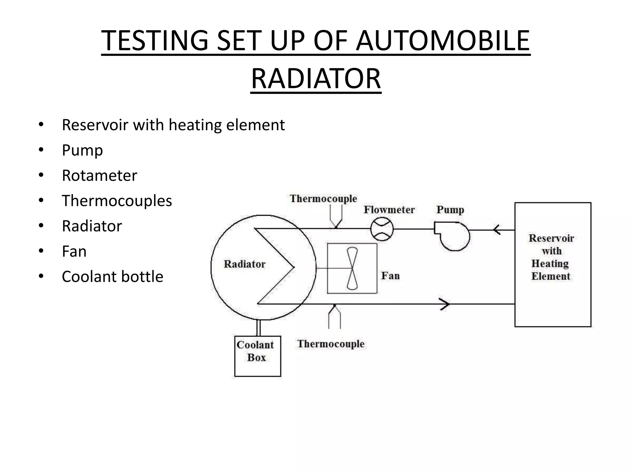

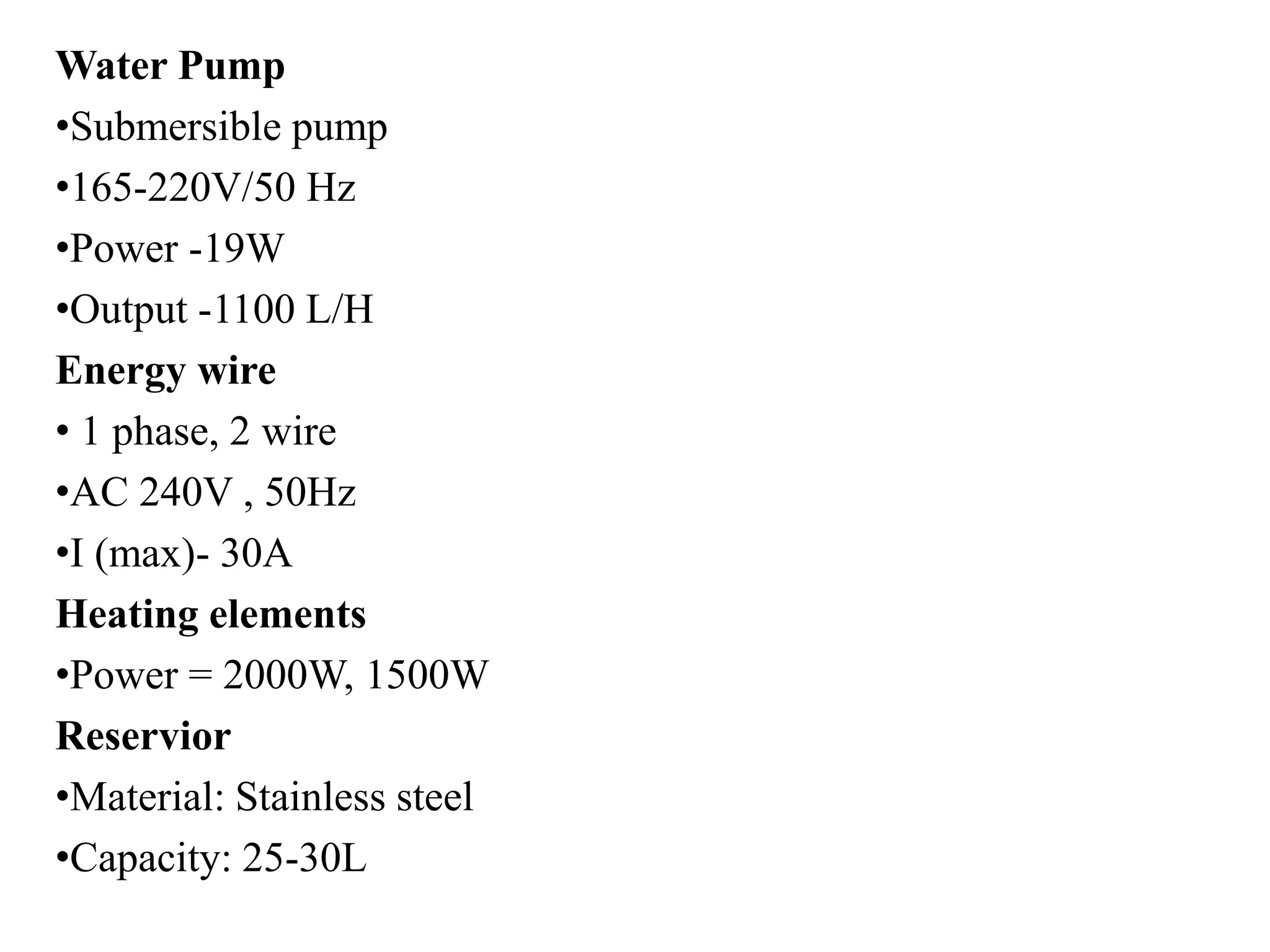
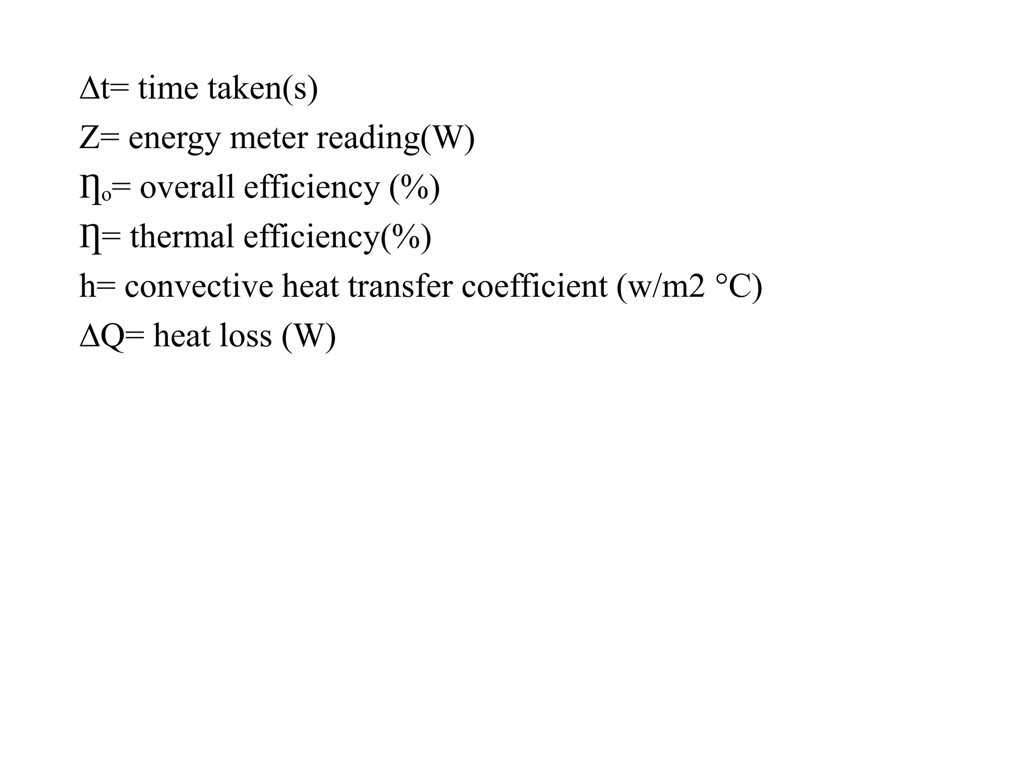
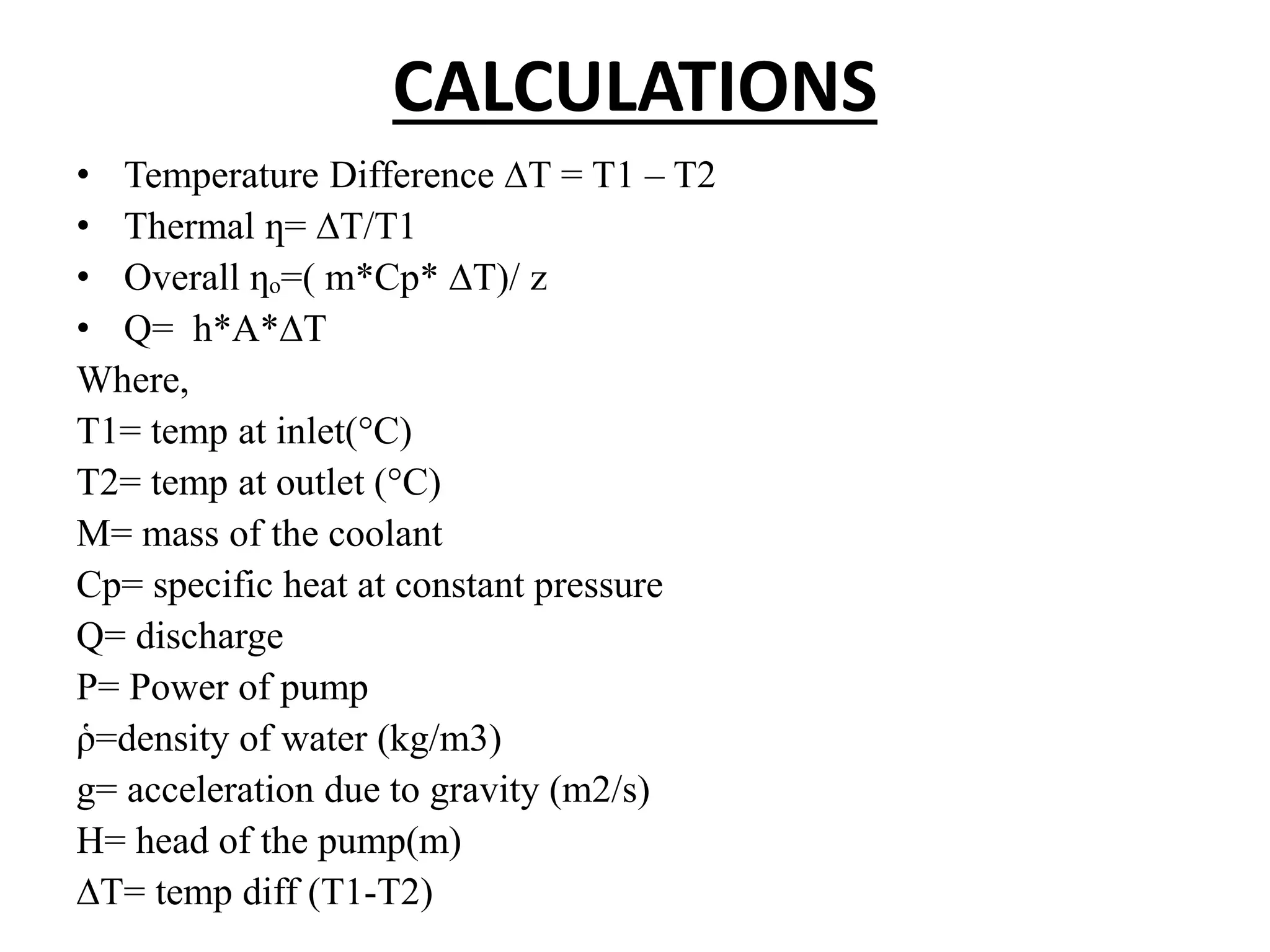
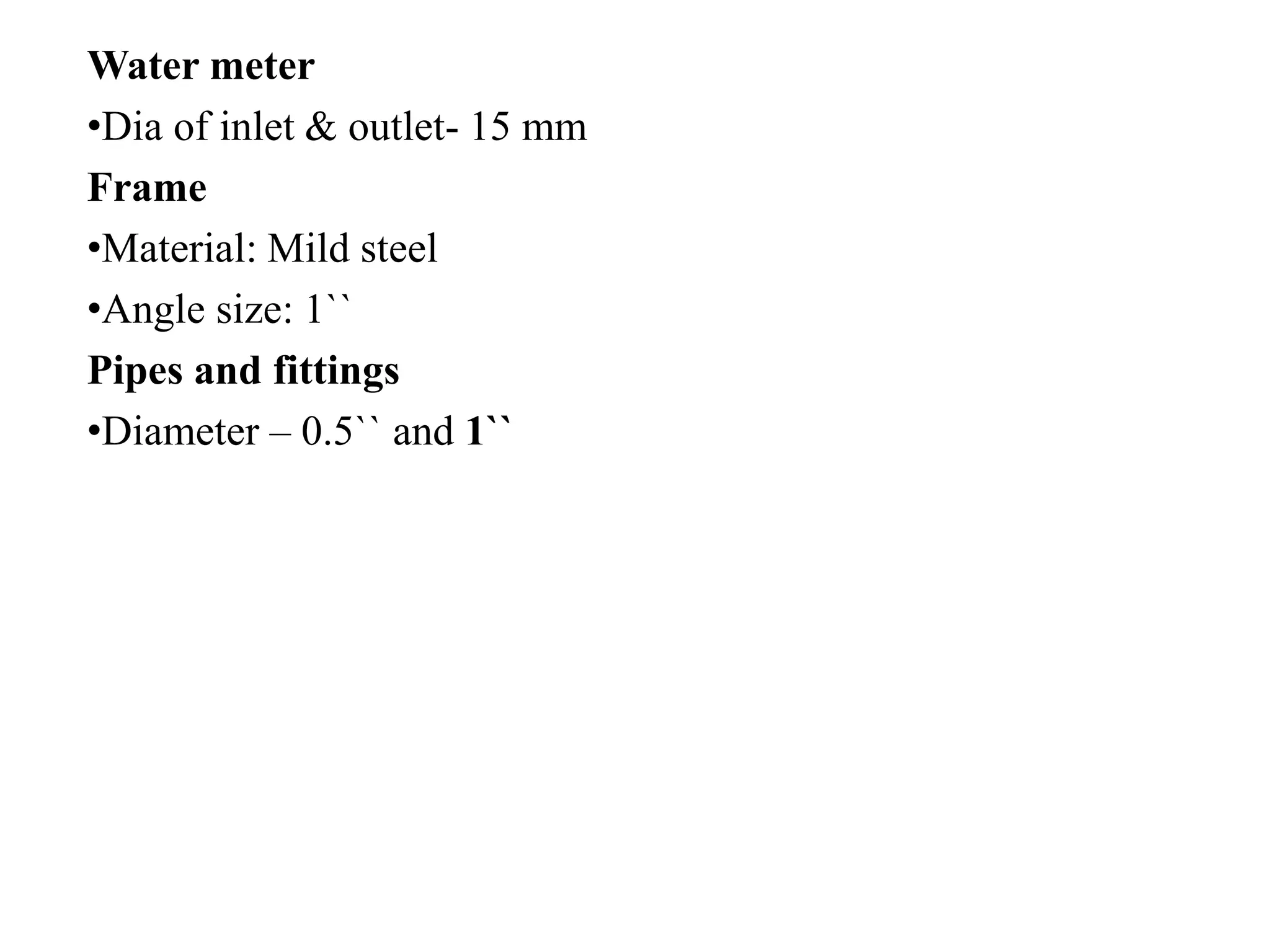
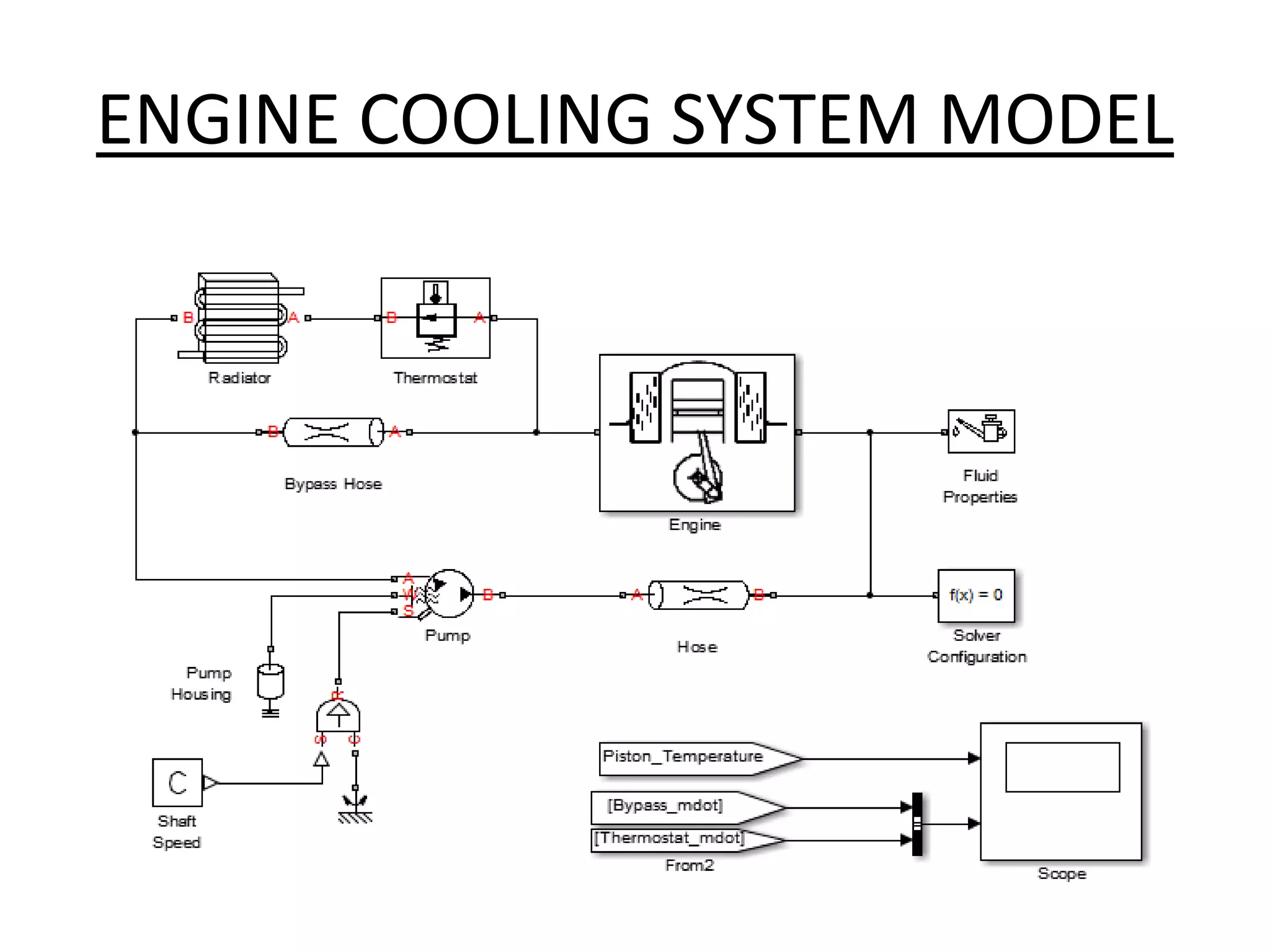
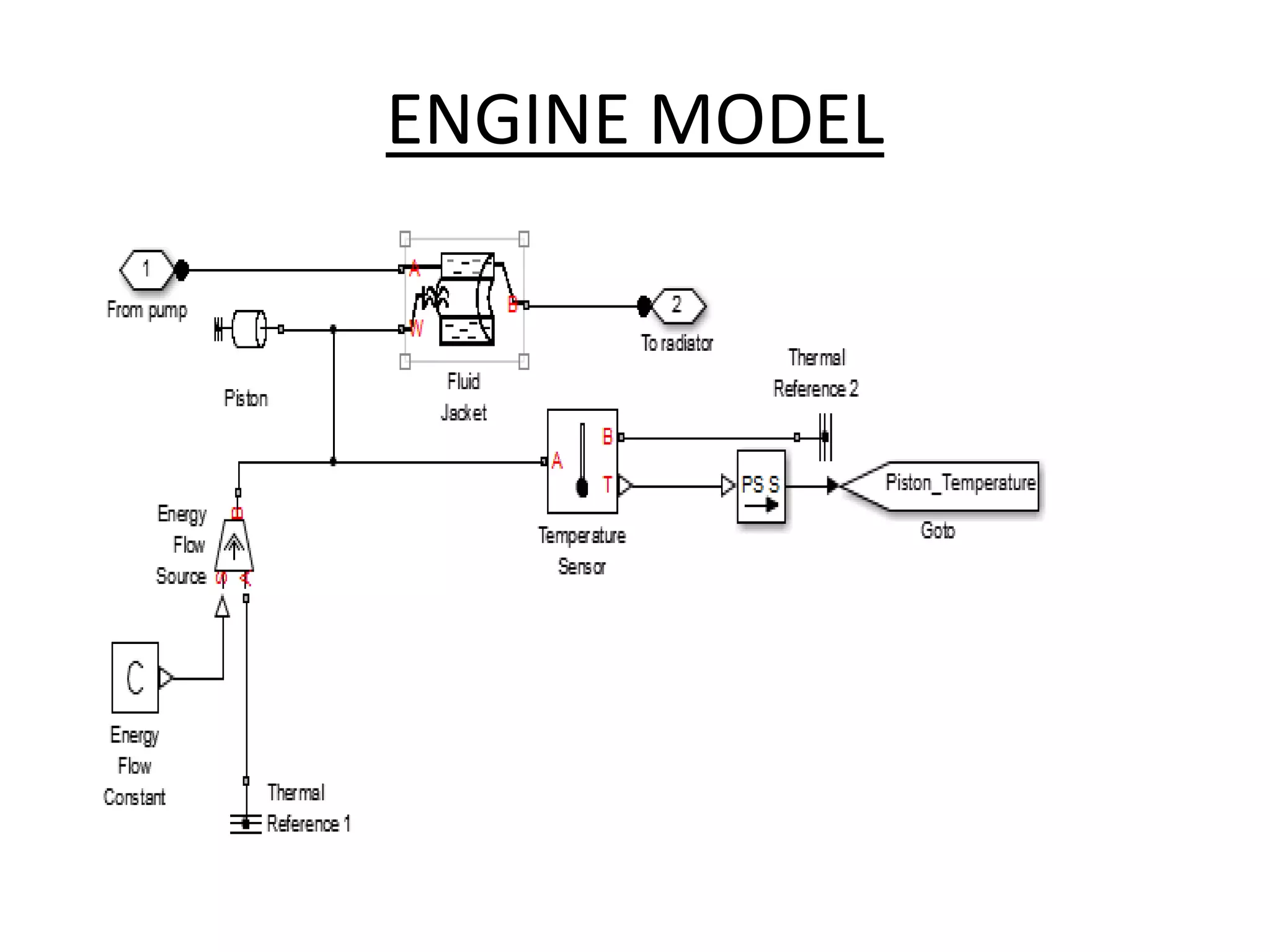

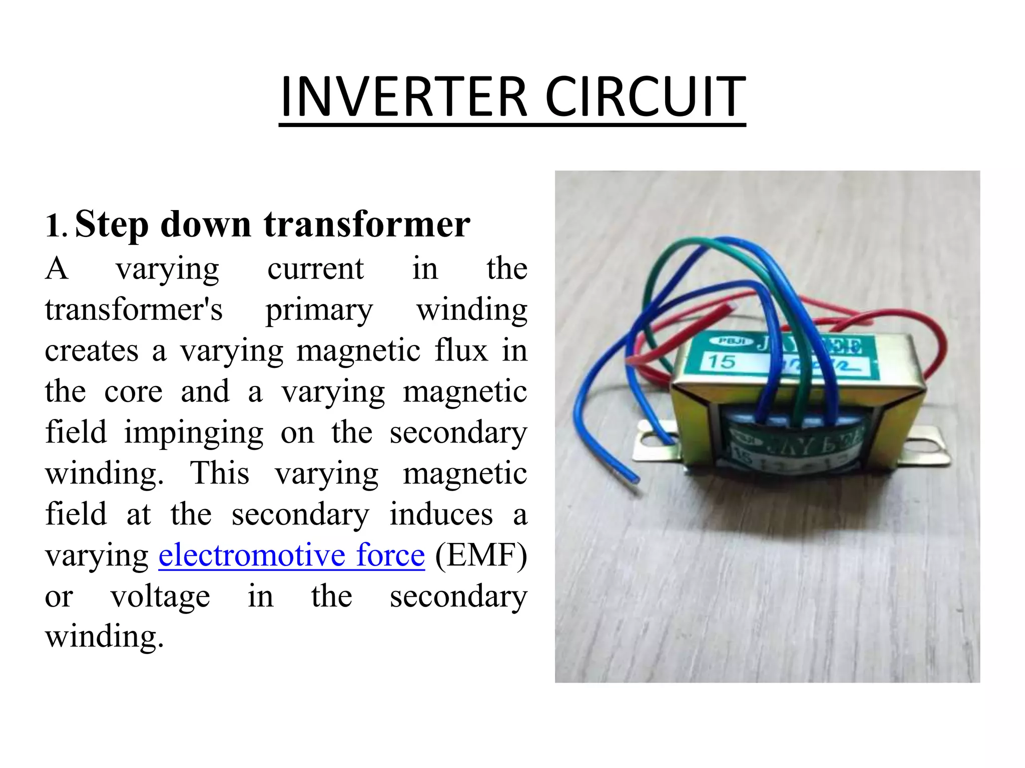
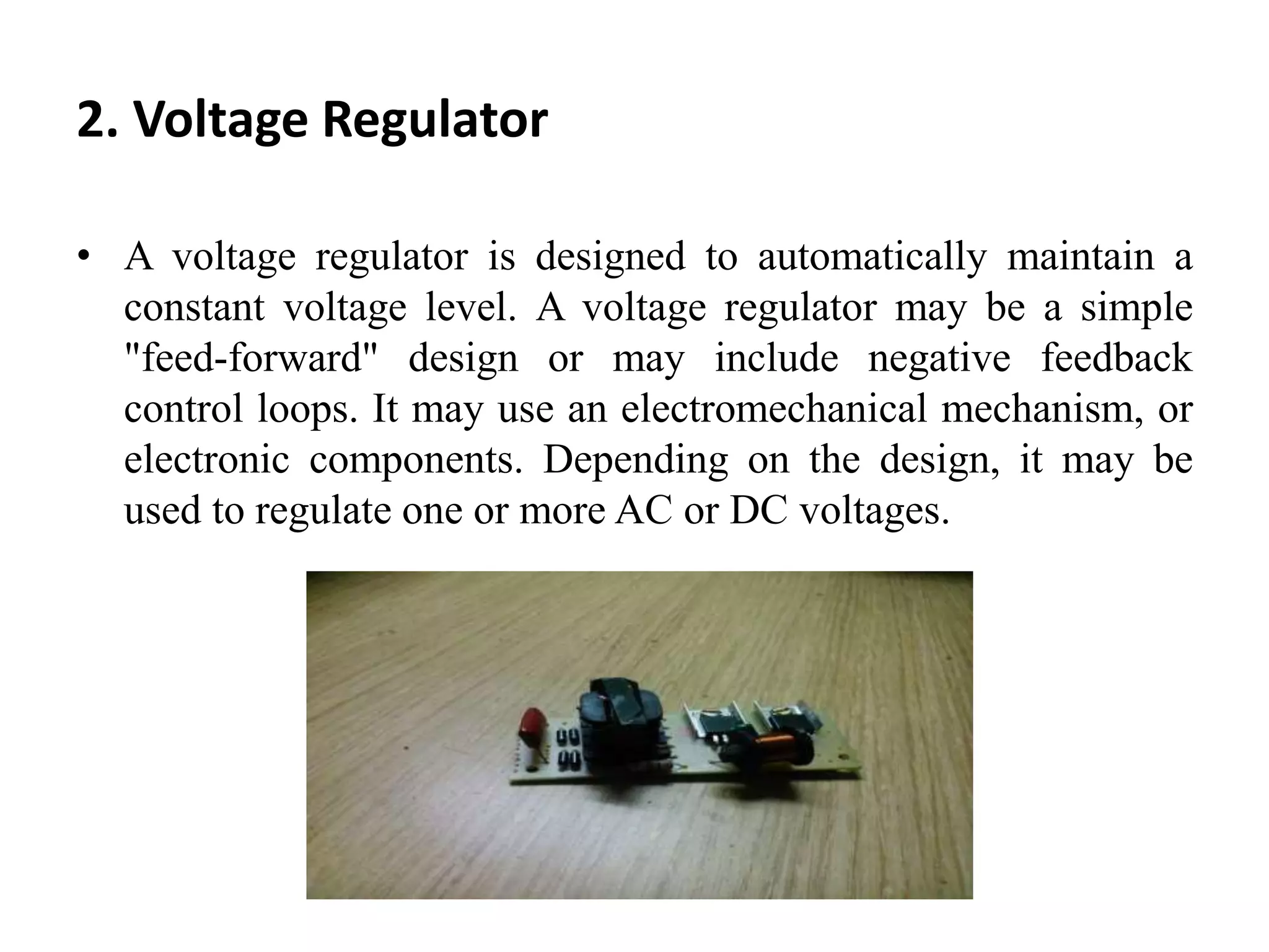
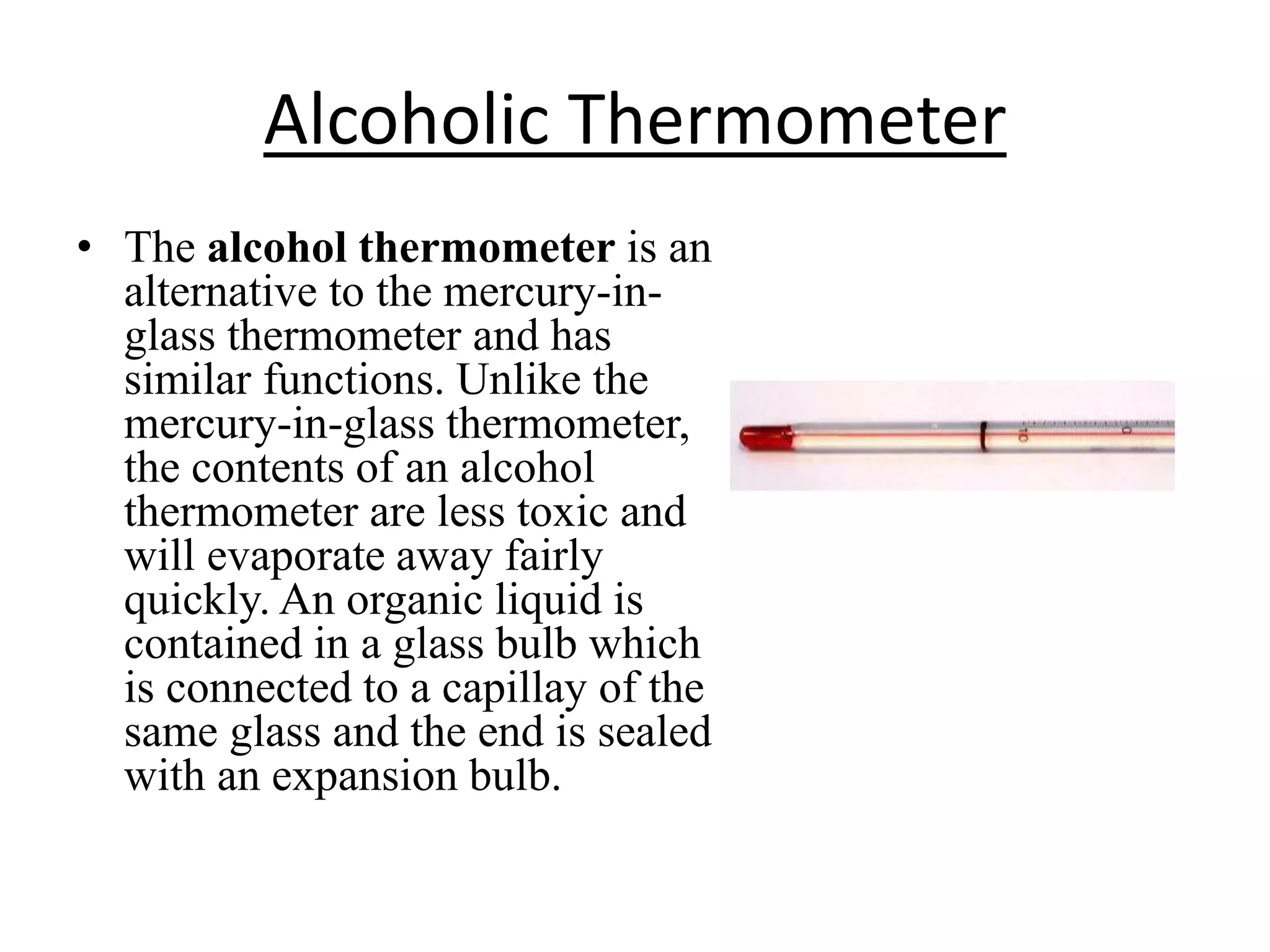
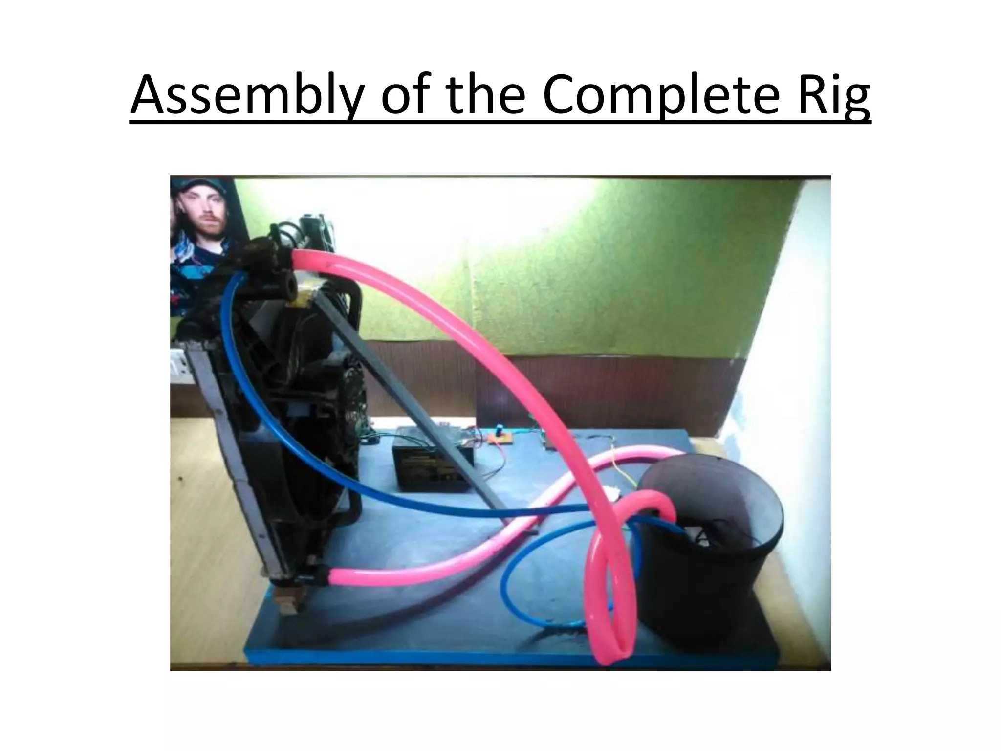
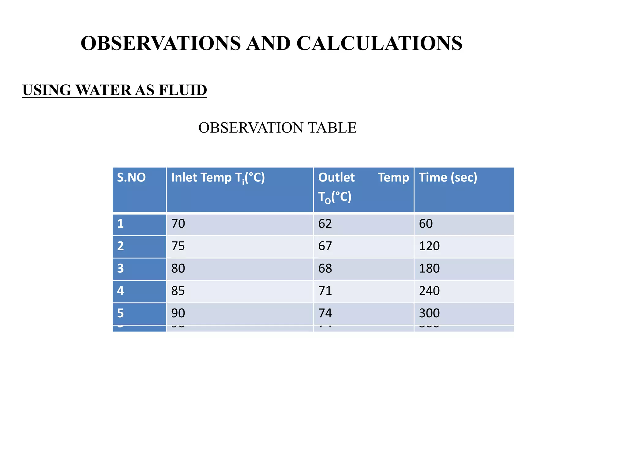
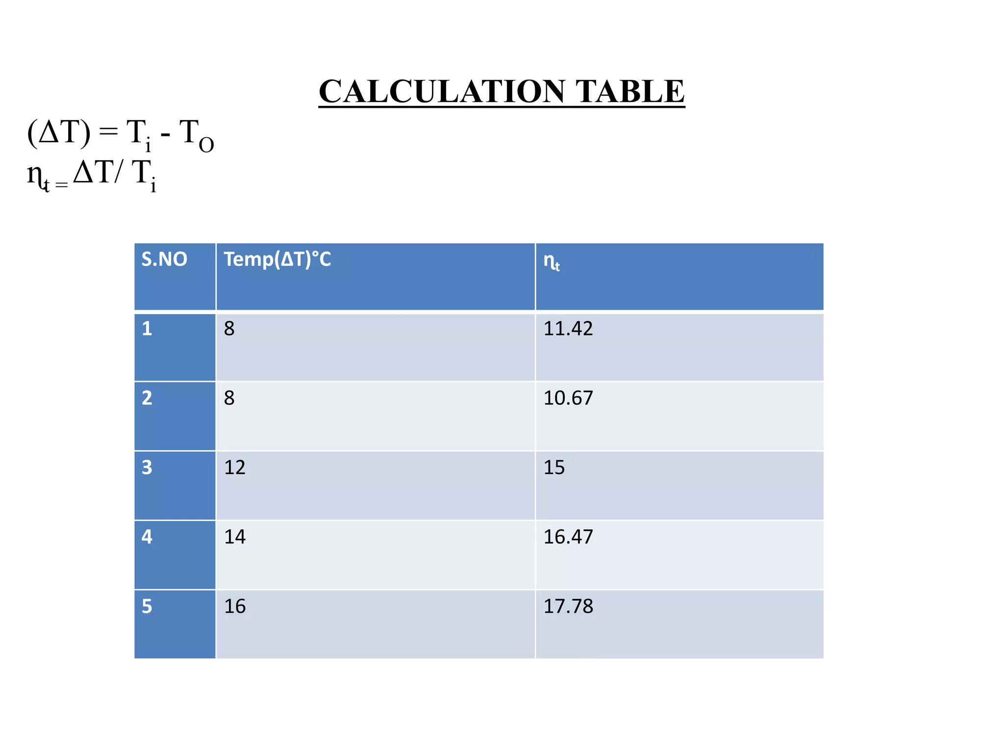
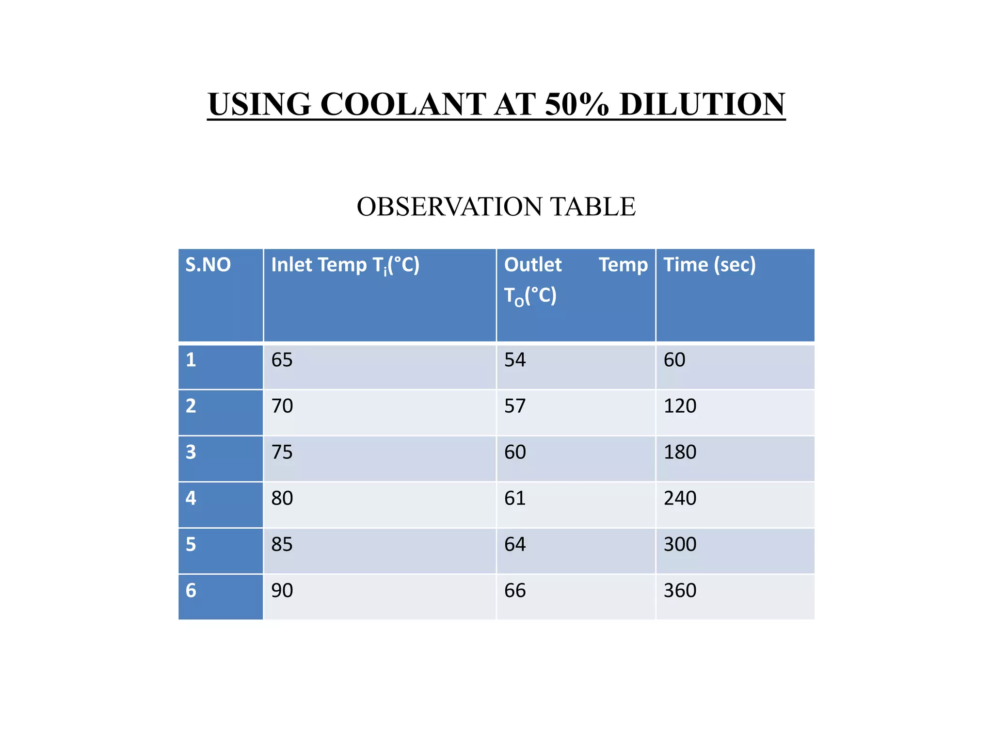
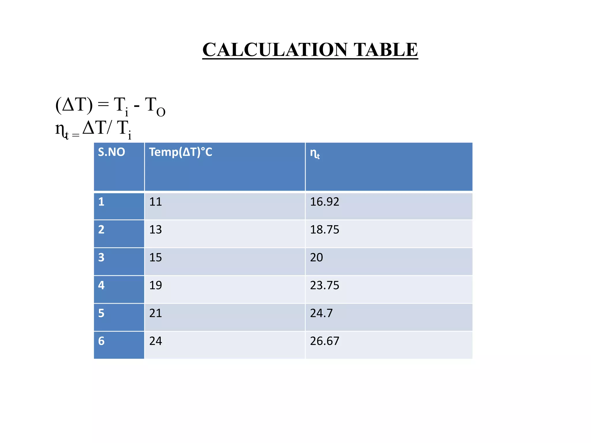
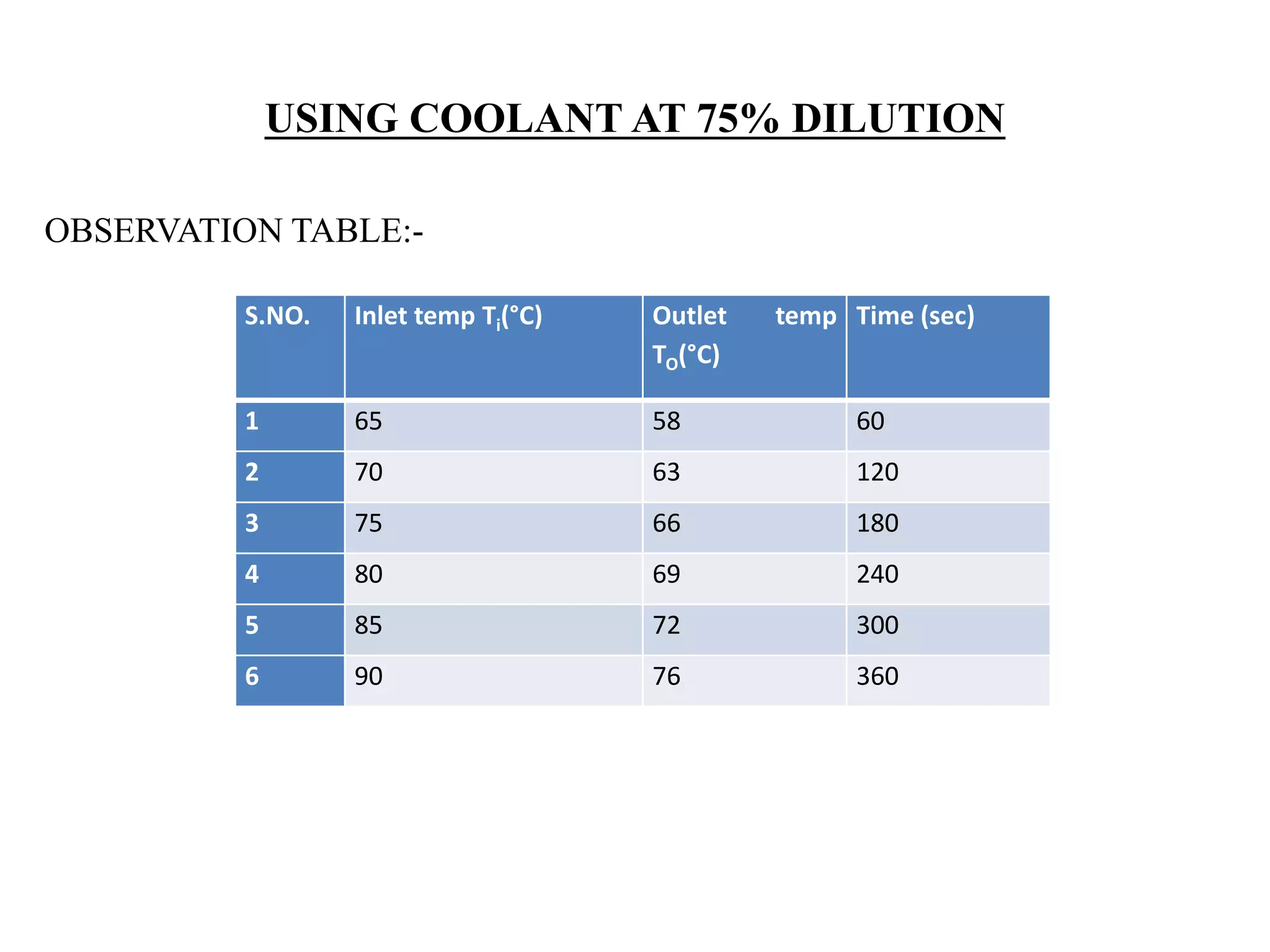
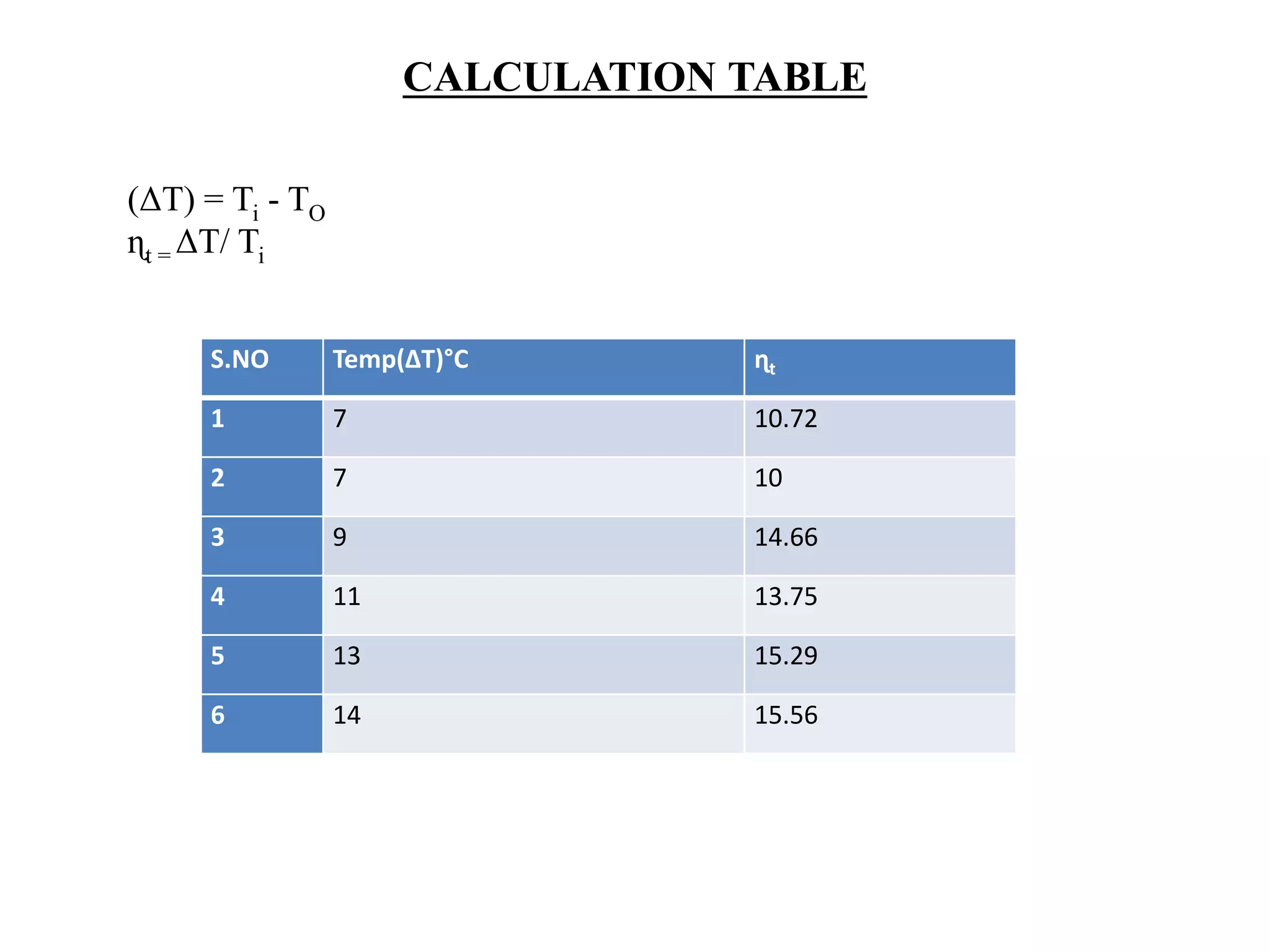
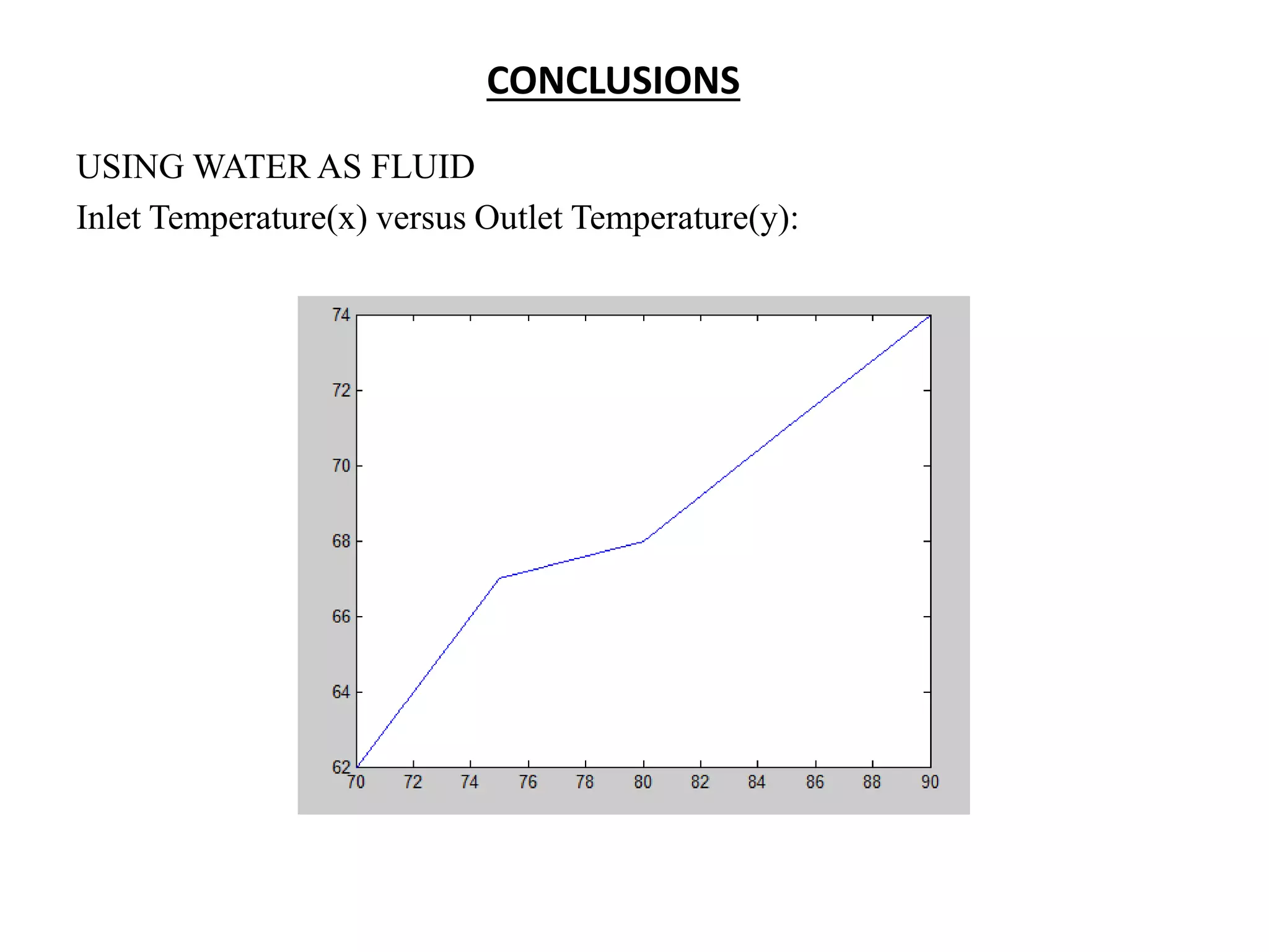
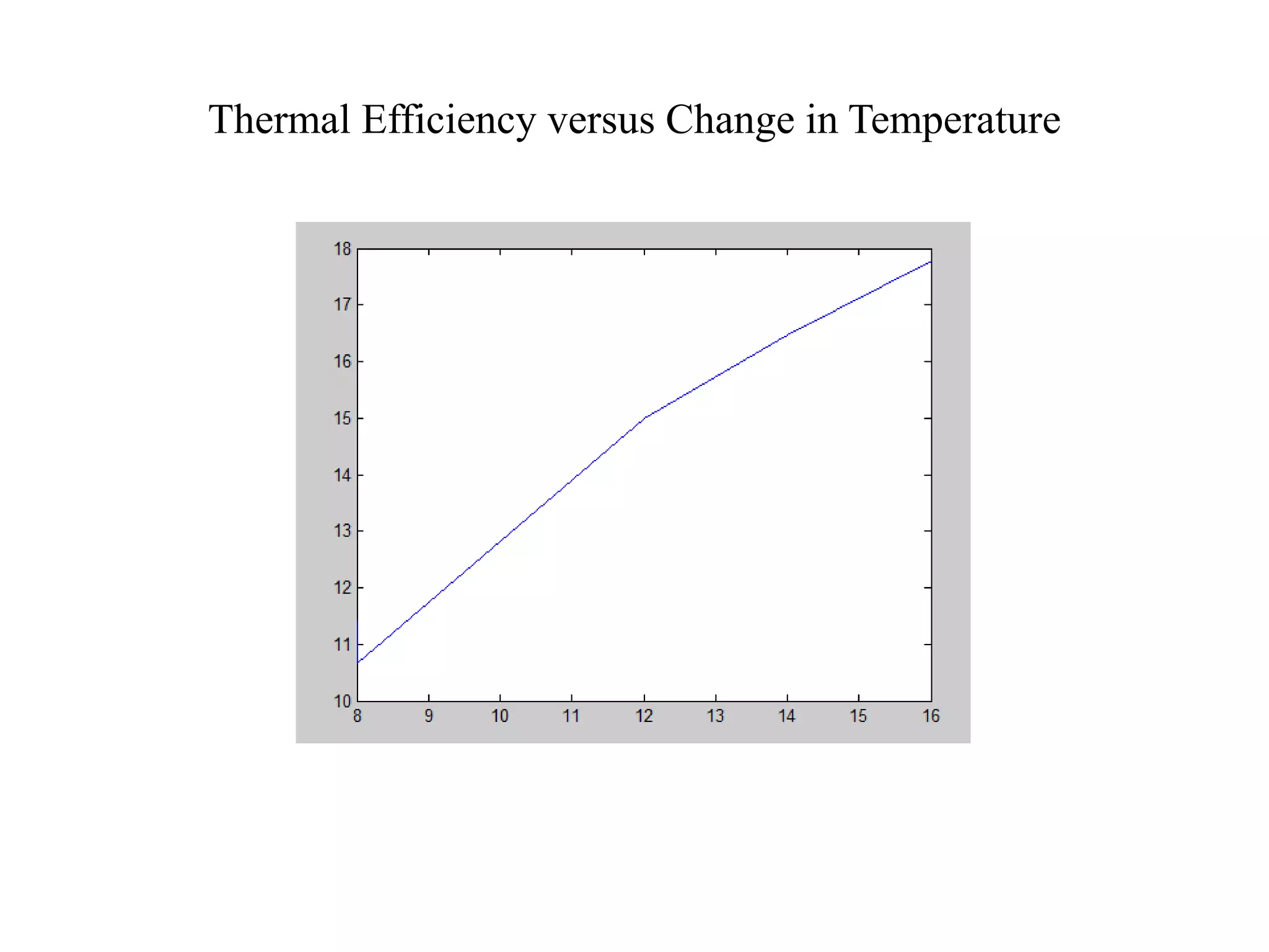
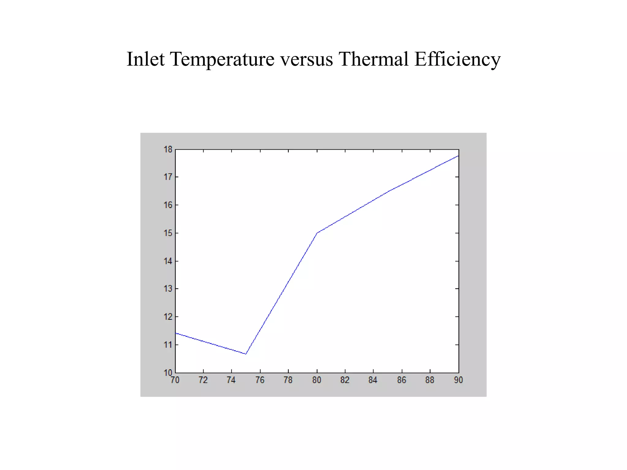
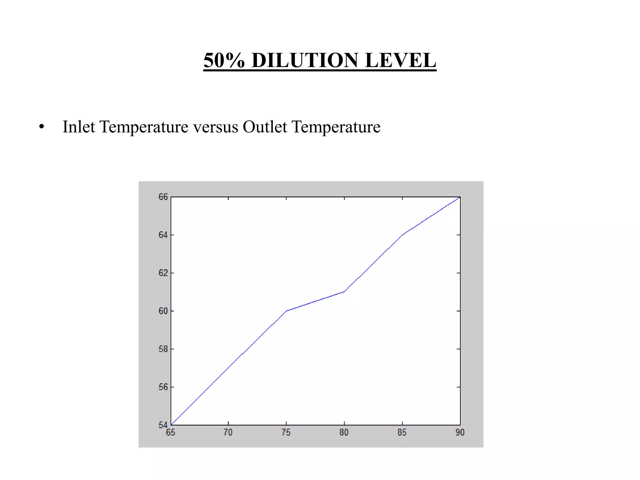
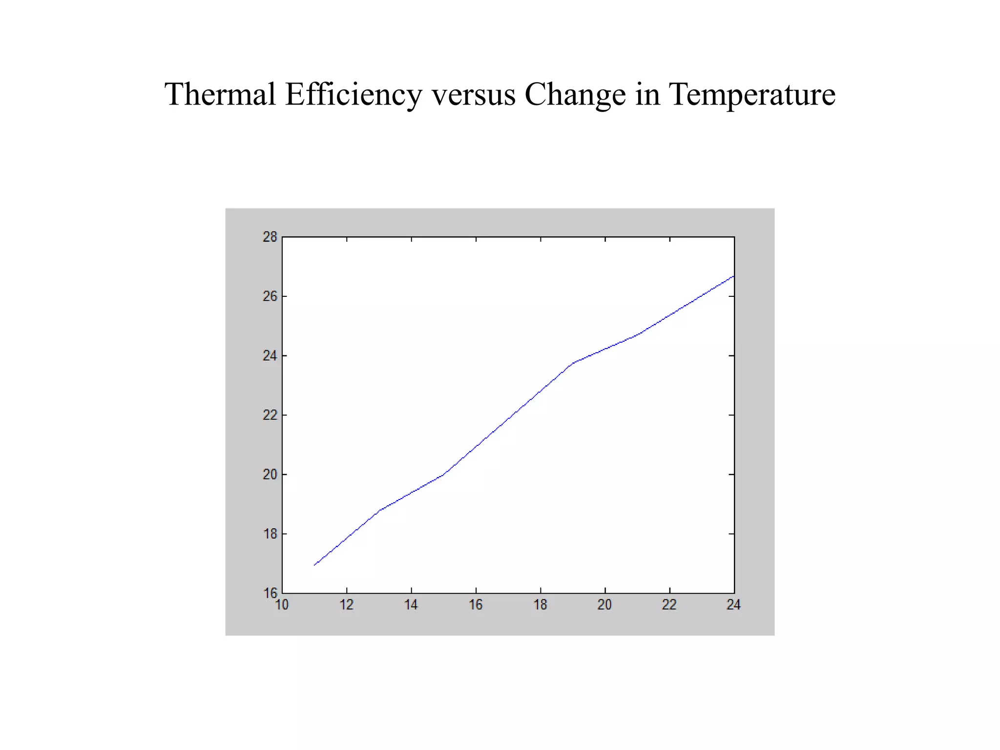
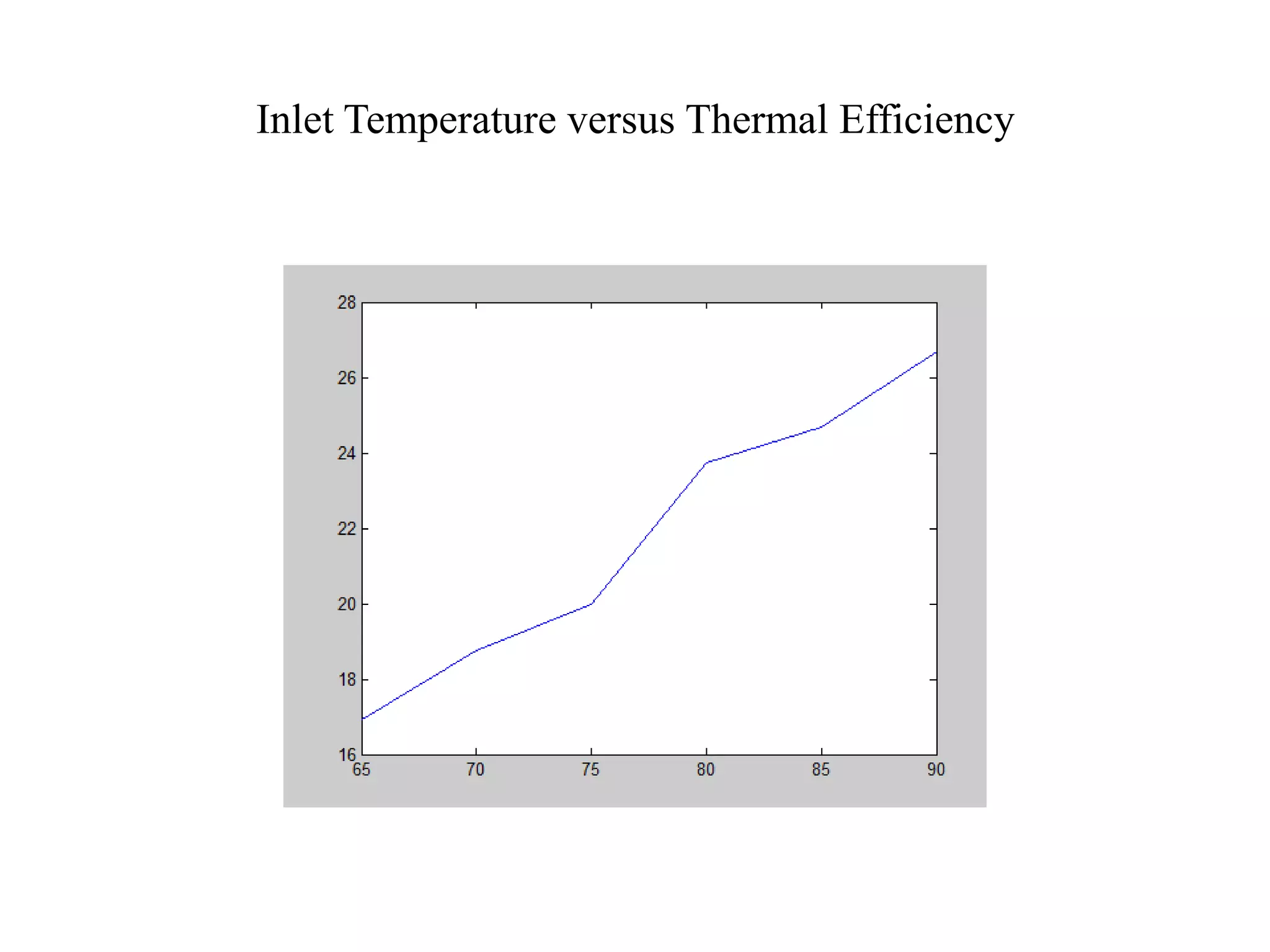
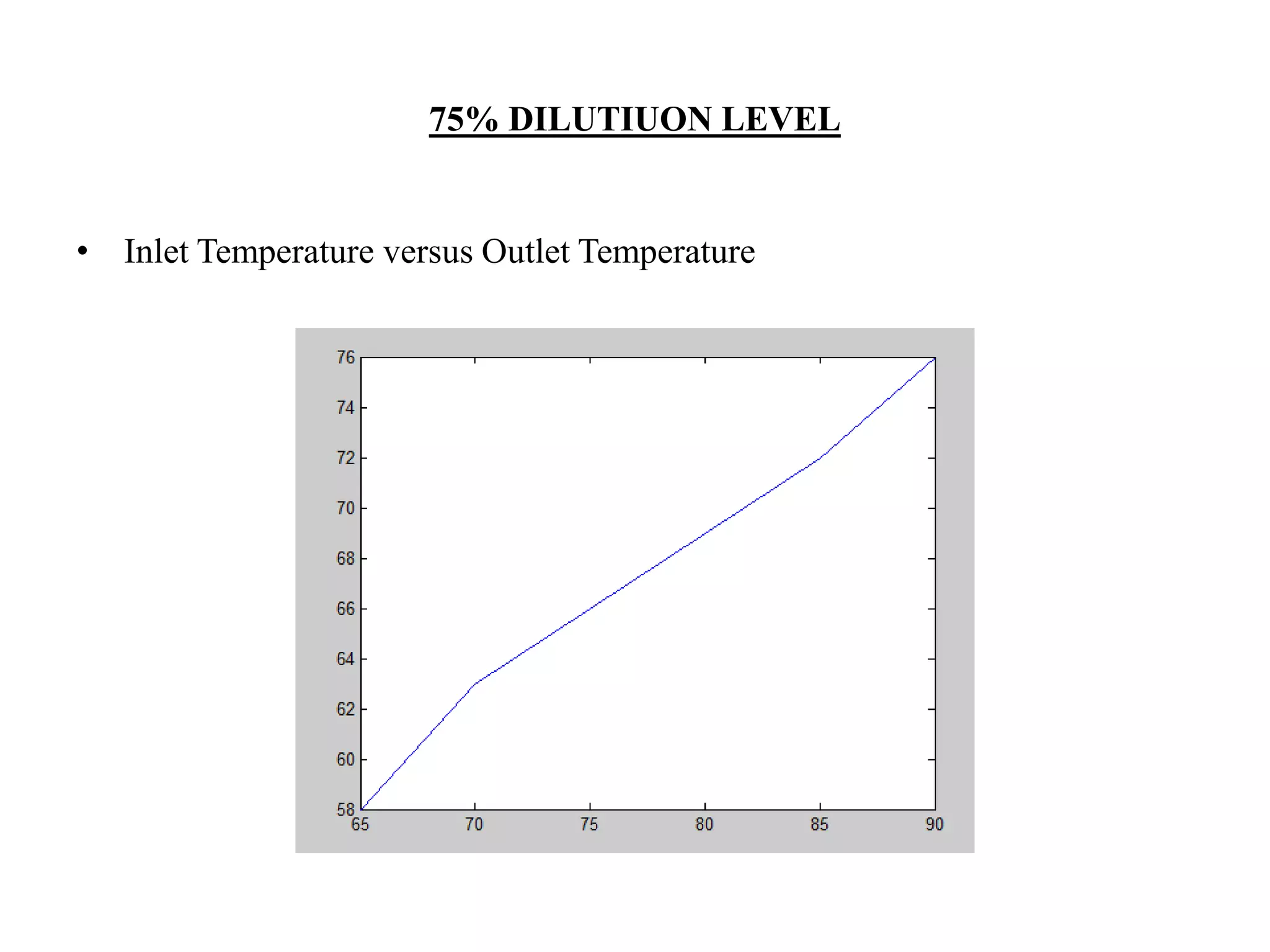
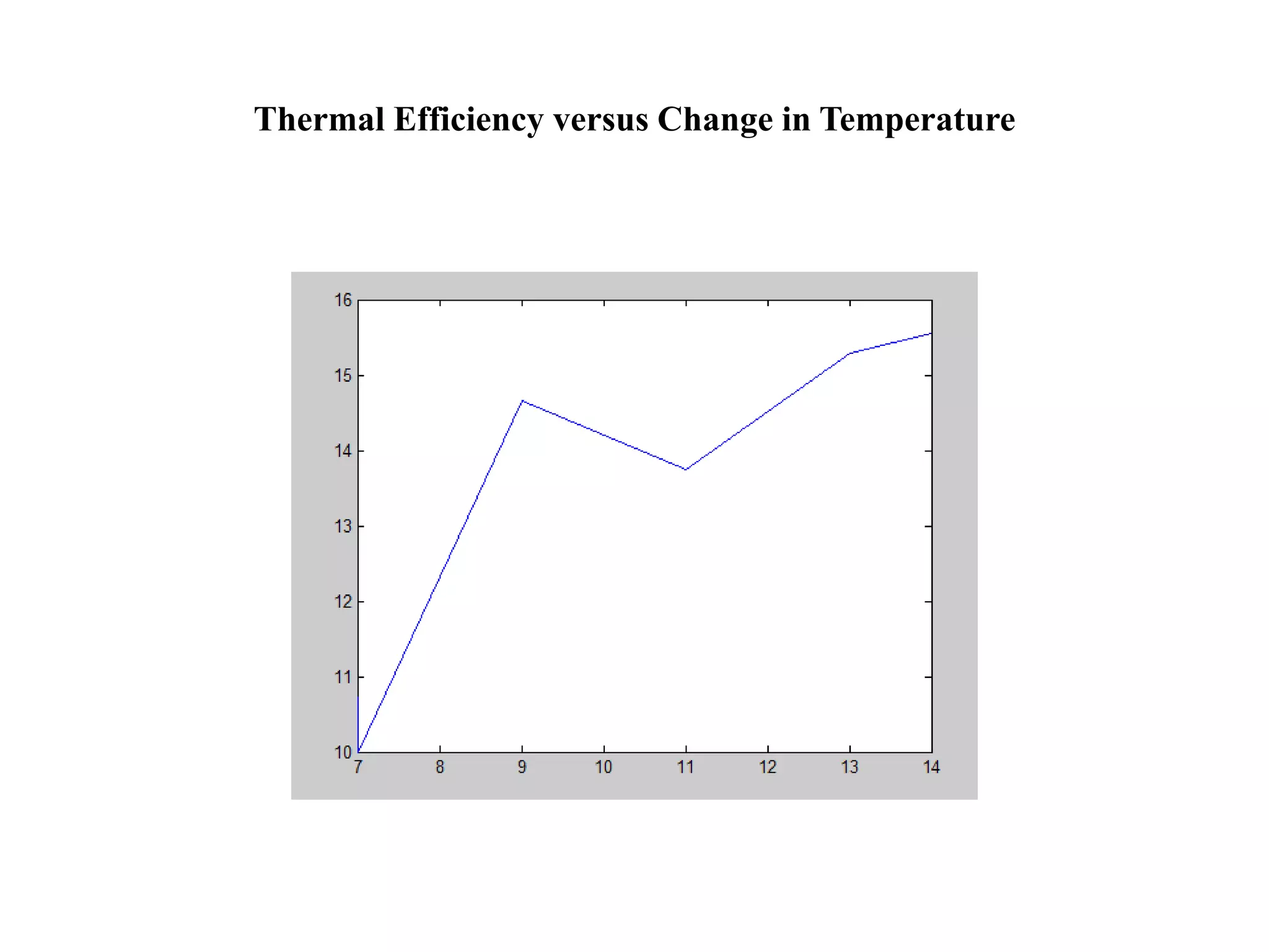
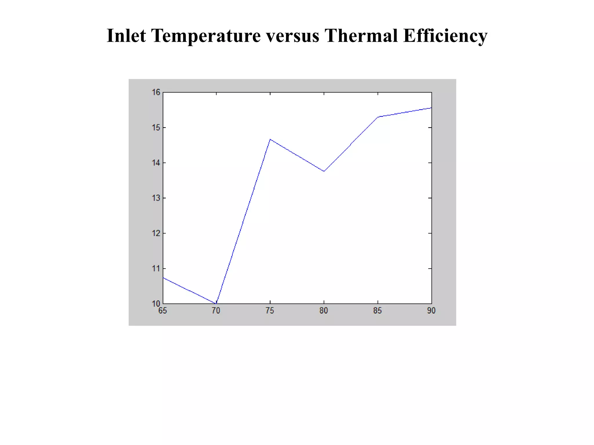
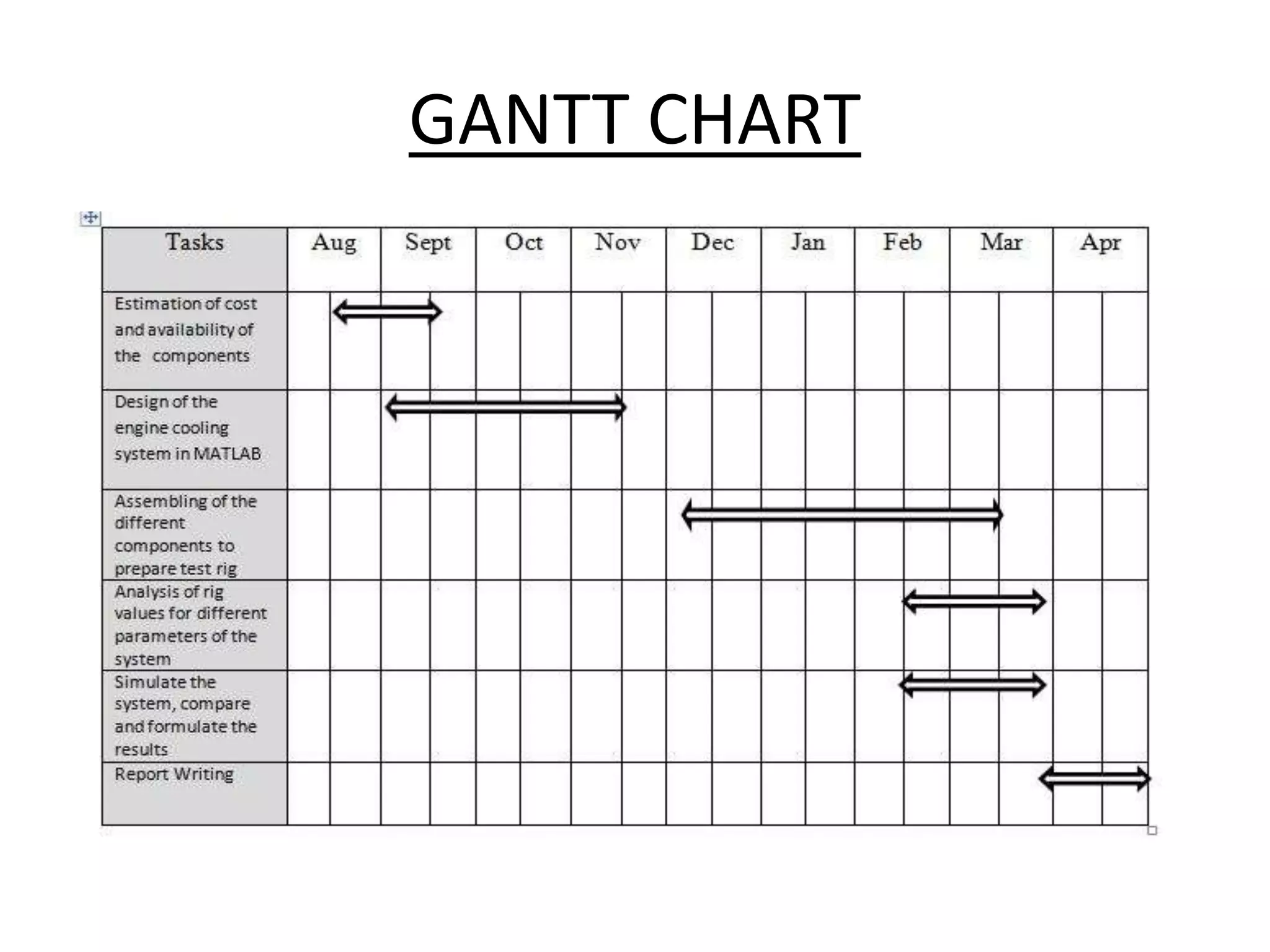


This document describes the design, fabrication, and analysis of an automobile radiator test rig using MATLAB. The main divisions of the project include estimating costs, designing the cooling system in MATLAB, assembling components to create the test rig, and analyzing rig values for different parameters. The test rig components include a reservoir, pump, rotameter, thermocouples, radiator, fan, and coolant bottle. Experiments are conducted using water and coolant at different dilution levels. Observations of inlet/outlet temperatures and efficiency calculations are made. Results show inlet temperature decreases with increasing outlet temperature. Thermal efficiency increases with greater temperature difference. The project concludes with recommendations for further analysis and simulation of the system.