Downloaded 110 times
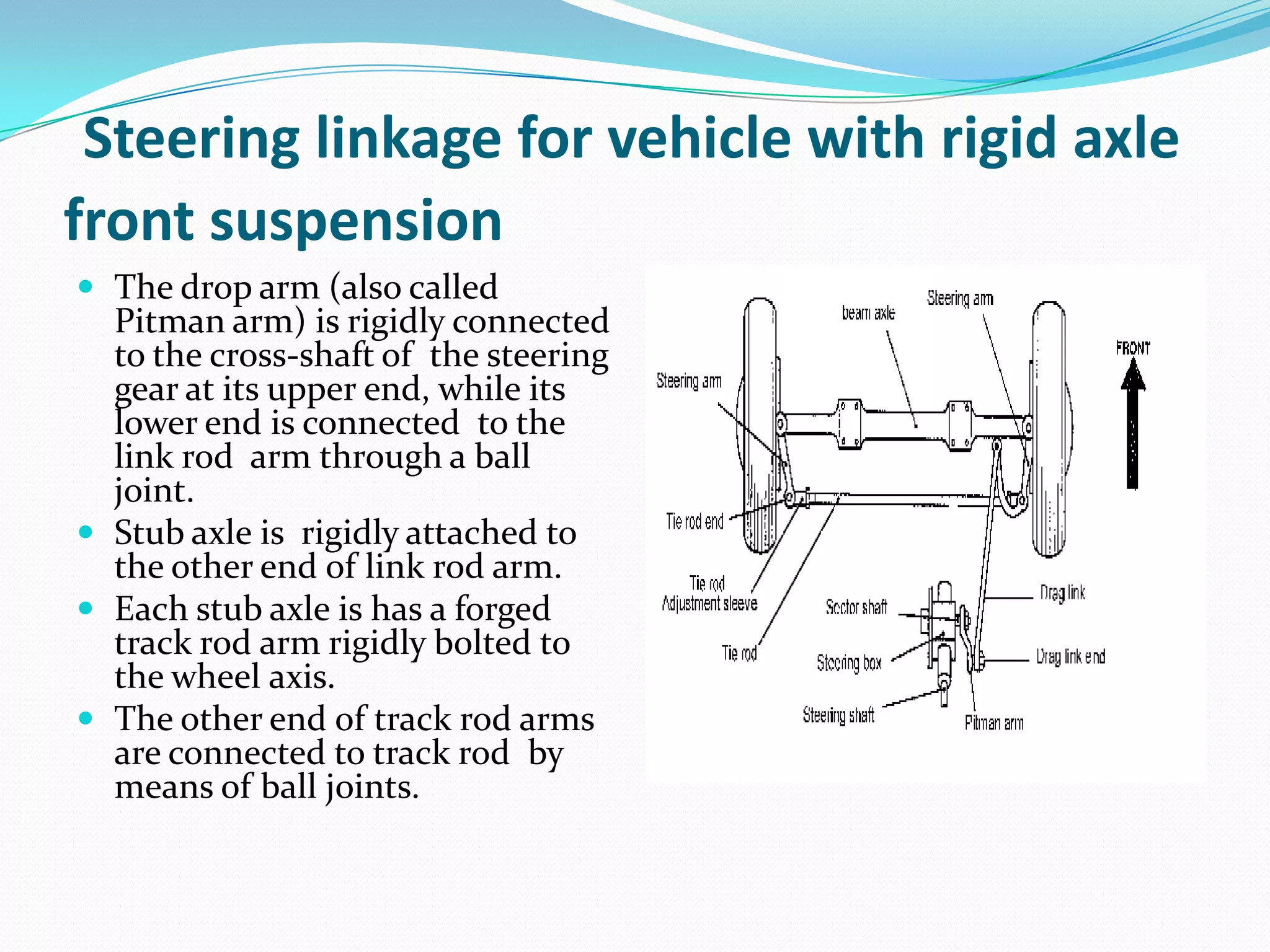
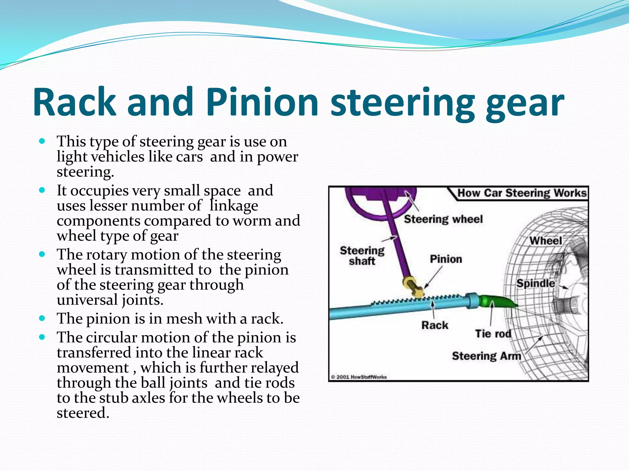
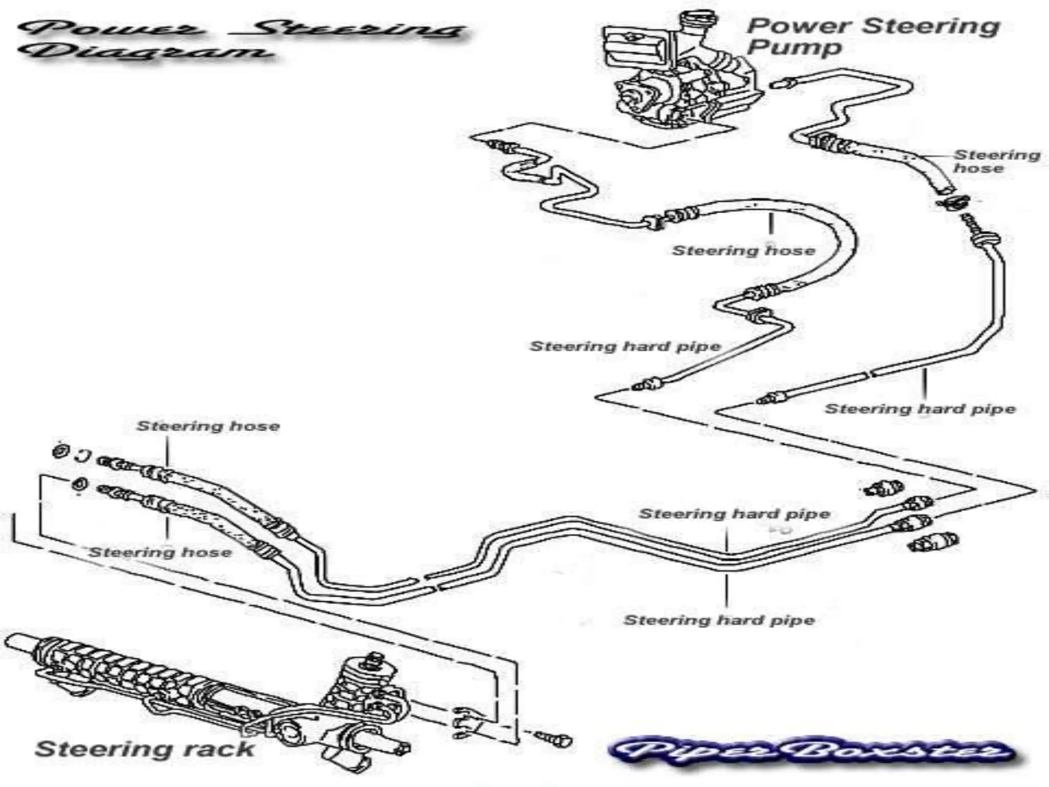
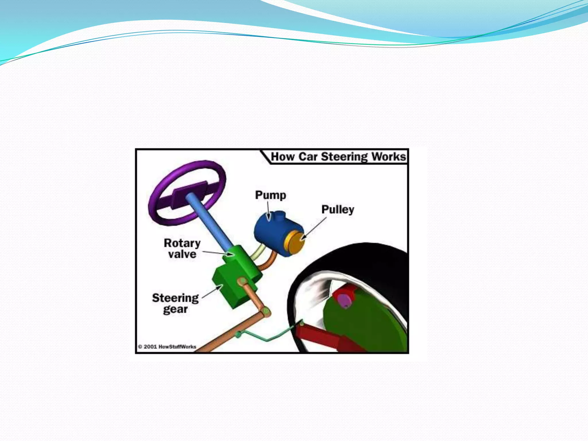


The document discusses steering systems and components. It describes steering linkages used in vehicles with rigid axle front suspensions and independent front suspensions. It also discusses different types of steering gears like rack and pinion gears, and how power steering systems and electronic power steering systems work. It provides details on Davis steering mechanism and Ackerman steering mechanism.


