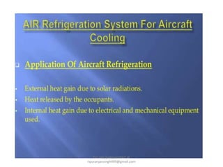
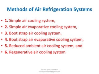
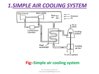
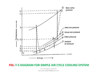
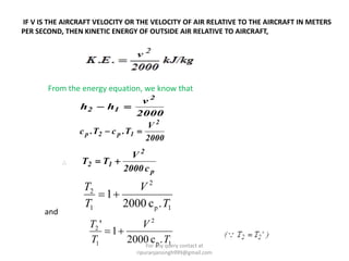
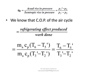
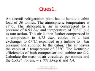
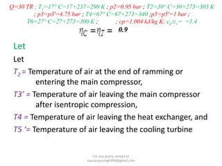
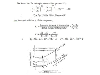
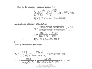
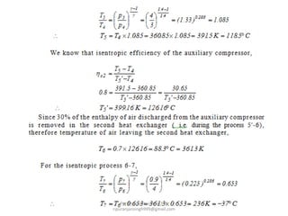
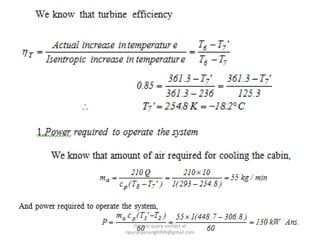
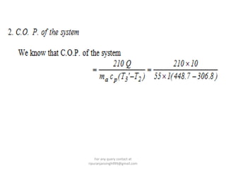
DEPARTMENT OF MECHANICAL ENGG. S.R.I.M.T, Lucknow
Ripuranjan Singh
Asst. professor
For any query contact at
ripuranjansingh999@gmail.com
For any query contact at
ripuranjansingh999@gmail.com
Methods of Air Refrigeration Systems
• 1. Simple air cooling system,
• 2. Simple air evaporative cooling system,
• 3. Boot strap air cooling system,
• 4. Boot strap air evaporative cooling system,
• 5. Reduced ambient air cooling system, and
• 6. Regenerative air cooling system.
For any query contact at
ripuranjansingh999@gmail.com
1.SIMPLE AIR COOLING SYSTEM
Fig:-Simple air cooling system
For any query contact at
ripuranjansingh999@gmail.com
FIG:-T-S DIAGRAM FOR SIMPLE AIR CYCLE COOLING SYSTEM
For any query contact at
ripuranjansingh999@gmail.com
IF V IS THE AIRCRAFT VELOCITY OR THE VELOCITY OF AIR RELATIVE TO THE AIRCRAFT IN METERS
PER SECOND, THEN KINETIC ENERGY OF OUTSIDE AIR RELATIVE TO AIRCRAFT,
From the energy equation, we know that
2000
v
hh
2
12 
2000
V
T.cT.c
2
1p2p 

p
2
12
c2000
V
TT 
1p
2
1
2
.c2000
1
T
V
T
T

1p
2
1
2
.c2000
1
'
T
V
T
T

and
For any query contact at
ripuranjansingh999@gmail.com
• We know that C.O.P. of the air cycle
'T'T
'TT
)'T'(Tcm
)'T(Tcm
23
56
23pa
56pa






For any query contact at
ripuranjansingh999@gmail.com
If Q tonnes of refrigeration is the cooling load in
the cabin, then the air required for the
refrigeration purpose,
Power required for the refrigeration system
kW
60
)''( 23 TTcm
p
pa 

and C.O.P. of the refrigerating system
For any query contact at
ripuranjansingh999@gmail.com
2.Simple Air Evaporative Cooling system
For any query contact at
ripuranjansingh999@gmail.com
T-s Diagram
For any query contact at
ripuranjansingh999@gmail.com
For any query contact at
ripuranjansingh999@gmail.com
3.BOOT-STRAP AIR COOLING SYSTEM
• he term Bootstrap as used in Air Cycle Refrigeration
indicates a system in which the pressure of the
working fluid is raised in two levels by using two
compressors, before the working fluid which is air,
expands in the turbine section
The main components of this system are:
• Two heat exchangers (air cooler and after cooler)
• A secondary compressor, which is driven by the
turbine of the cooling system
For any query contact at
ripuranjansingh999@gmail.com
For any query contact at
ripuranjansingh999@gmail.com
For any query contact at
ripuranjansingh999@gmail.com
4.Boot-strap Air Evaporative Cooling
System
For any query contact at
ripuranjansingh999@gmail.com
T-s diagram
For any query contact at
ripuranjansingh999@gmail.com
If Q tones of refrigeration is the cooling load in the cabin,
then the quantity of air required for the refrigeration purpose
will be
For any query contact at
ripuranjansingh999@gmail.com
For any query contact at
ripuranjansingh999@gmail.com
5.Regenerative air cooling system
Fig:-Regenerative air cooling system
For any query contact at
ripuranjansingh999@gmail.com
Fig. :-T-s diagram for regenerative air cooling system
For any query contact at
ripuranjansingh999@gmail.com
6. Reduced Ambient Air Cooling
System
For any query contact at
ripuranjansingh999@gmail.com
Fig:-Reduced ambient air cooling system
For any query contact at
ripuranjansingh999@gmail.com
Fig:-T-S diagram for reduced ambient air cycle cooling
system.For any query contact at
ripuranjansingh999@gmail.com
For any query contact at
ripuranjansingh999@gmail.com
ADVANTAGES
For any query contact at
ripuranjansingh999@gmail.com
Comparison of Various Air Cooling Systems
used for Aircraft
• Comparison of Various Air Cooling Systems used for
Aircraft are shown in Fig.
• These curves show the dry air rated turbine discharge
temperature (DART) against the Mach number.
• we see that the simple air cooling system gives maximum
cooling effect on the ground surface and decreases as the
speed of aircraft increases.
• .The boot strap system on the other hand, requires the
air plane to be in flight so that the ram air can be used
for cooling in the heat exchangers
For any query contact at
ripuranjansingh999@gmail.com
• For high speed aircrafts, the boot strap evaporative or
regenerative systems are used because they give lower
turbine discharge temperature than the simple cooling
system.
Fig. Performance curves for various air cooling systems.
For any query contact at
ripuranjansingh999@gmail.com
Ques1.
An aircraft refrigeration plant has to handle a cabin
load of 30 tonnes. The atmospheric temperature is
17°C. The atmospheric air is compressed to a
pressure of 0.95 bar and temperature of 30° C due
to ram action. This air is then further compressed in
a compressor to 4.75 bar, cooled in a heat
exchanger to 67°C, expanded in a turbine to I bar
pressure and supplied to the cabin. The air leaves
the cabin at a temperature of 27°C. The isentropic
efficiencies of both compressor and turbine are 0.9.
Calculate the mass of air circulated per minute and
the C.O.P. For air, = 1.004 kJ/kg K and 1.4.
For any query contact at
ripuranjansingh999@gmail.com
Q=30 TR ; T1=17° C=17+237=290 K ; p2=0.95 bar ; T2=30° C=30+273=303 K
; p3=p3'=4.75 bar ; T4=67° C=67+273=340 ;p5=p5'=1 bar ;
T6=27° C=27+273=300 K ; ; cp=1.004 kJ/kg K; cp/cv= =1.4
0.9
Let
Let
T2 = Temperature of air at the end of ramming or
entering the main compressor,
T3’ = Temperature of air leaving the main compressor
after isentropic compression,
T4 = Temperature of air leaving the heat exchanger, and
T5 ‘= Temperature of air leaving the cooling turbine
For any query contact at
ripuranjansingh999@gmail.com
For any query contact at
ripuranjansingh999@gmail.com
For any query contact at
ripuranjansingh999@gmail.com
Ques.2
A boot-strap cooling system of 10 TR capacity is used in an
aeroplane. The ambient air temperature and pressure are 20°C
and 0.85 bar respectively. The pressure of air increases from
0.85 bar to 1 bar due to ramming action of air. "The pressure of
air discharged from the main compressor is 3 bar. The discharge
pressure of air from the auxiliary compressor is 4 bar. The
isentropic efficiency of each of the compressor is 80%, while
that of turbine is 85%. 50% of the enthalpy of air discharged
from the main compressor is removed in the first heat
exchanger and 30% of the enthalpy of air discharged from the
auxiliary compressor is removed in the second heat exchanger
using rammed air. Assuming ramming action to be isentropic,
the required cabin pressure of 0.9 bar and temperature of the
air leaving the cabin not more than 20° C, find : 1. the power
required to operate the system, and 2. the C.O.P. of the system.
Draw the schematic and temperature -entropy diagram of the
system. Take =1.4 and cp =1 kJ/kg K
For any query contact at
ripuranjansingh999@gmail.com
solution
Given : Q = 10 TR ; T1 = 20° C = 20 + 273 = 293 K ; p1 = 0.85 bar ; p2 = 1 bar ;
P3=P3'=P4=3 bar ;p5 = p5' = p6 =4 bar ;  2C1C  80% =0.8 ; T =
85% = 0.85 ;  877 ' ppp 0.9 bar ; T8 =200
C= 20+273 =293 K ; y=
1.4; cp = 1 kJ/kgK
For any query contact at
ripuranjansingh999@gmail.com
For any query contact at
ripuranjansingh999@gmail.com
For any query contact at
ripuranjansingh999@gmail.com
For any query contact at
ripuranjansingh999@gmail.com
For any query contact at
ripuranjansingh999@gmail.com
For any query contact at
ripuranjansingh999@gmail.com
For any query contact at
ripuranjansingh999@gmail.com
Thank You
For any query contact at ripuranjansingh999@gmail.com
For any query contact at
ripuranjansingh999@gmail.com

Aircraft refrigeration system (air cooling system)

  • 1.
    DEPARTMENT OF MECHANICALENGG. S.R.I.M.T, Lucknow Ripuranjan Singh Asst. professor For any query contact at ripuranjansingh999@gmail.com
  • 2.
    For any querycontact at ripuranjansingh999@gmail.com
  • 3.
    Methods of AirRefrigeration Systems • 1. Simple air cooling system, • 2. Simple air evaporative cooling system, • 3. Boot strap air cooling system, • 4. Boot strap air evaporative cooling system, • 5. Reduced ambient air cooling system, and • 6. Regenerative air cooling system. For any query contact at ripuranjansingh999@gmail.com
  • 4.
    1.SIMPLE AIR COOLINGSYSTEM Fig:-Simple air cooling system For any query contact at ripuranjansingh999@gmail.com
  • 5.
    FIG:-T-S DIAGRAM FORSIMPLE AIR CYCLE COOLING SYSTEM For any query contact at ripuranjansingh999@gmail.com
  • 6.
    IF V ISTHE AIRCRAFT VELOCITY OR THE VELOCITY OF AIR RELATIVE TO THE AIRCRAFT IN METERS PER SECOND, THEN KINETIC ENERGY OF OUTSIDE AIR RELATIVE TO AIRCRAFT, From the energy equation, we know that 2000 v hh 2 12  2000 V T.cT.c 2 1p2p   p 2 12 c2000 V TT  1p 2 1 2 .c2000 1 T V T T  1p 2 1 2 .c2000 1 ' T V T T  and For any query contact at ripuranjansingh999@gmail.com
  • 7.
    • We knowthat C.O.P. of the air cycle 'T'T 'TT )'T'(Tcm )'T(Tcm 23 56 23pa 56pa       For any query contact at ripuranjansingh999@gmail.com
  • 8.
    If Q tonnesof refrigeration is the cooling load in the cabin, then the air required for the refrigeration purpose, Power required for the refrigeration system kW 60 )''( 23 TTcm p pa   and C.O.P. of the refrigerating system For any query contact at ripuranjansingh999@gmail.com
  • 9.
    2.Simple Air EvaporativeCooling system For any query contact at ripuranjansingh999@gmail.com
  • 10.
    T-s Diagram For anyquery contact at ripuranjansingh999@gmail.com
  • 11.
    For any querycontact at ripuranjansingh999@gmail.com
  • 12.
    3.BOOT-STRAP AIR COOLINGSYSTEM • he term Bootstrap as used in Air Cycle Refrigeration indicates a system in which the pressure of the working fluid is raised in two levels by using two compressors, before the working fluid which is air, expands in the turbine section The main components of this system are: • Two heat exchangers (air cooler and after cooler) • A secondary compressor, which is driven by the turbine of the cooling system For any query contact at ripuranjansingh999@gmail.com
  • 13.
    For any querycontact at ripuranjansingh999@gmail.com
  • 14.
    For any querycontact at ripuranjansingh999@gmail.com
  • 15.
    4.Boot-strap Air EvaporativeCooling System For any query contact at ripuranjansingh999@gmail.com
  • 16.
    T-s diagram For anyquery contact at ripuranjansingh999@gmail.com
  • 17.
    If Q tonesof refrigeration is the cooling load in the cabin, then the quantity of air required for the refrigeration purpose will be For any query contact at ripuranjansingh999@gmail.com
  • 18.
    For any querycontact at ripuranjansingh999@gmail.com
  • 19.
    5.Regenerative air coolingsystem Fig:-Regenerative air cooling system For any query contact at ripuranjansingh999@gmail.com
  • 20.
    Fig. :-T-s diagramfor regenerative air cooling system For any query contact at ripuranjansingh999@gmail.com
  • 21.
    6. Reduced AmbientAir Cooling System For any query contact at ripuranjansingh999@gmail.com
  • 22.
    Fig:-Reduced ambient aircooling system For any query contact at ripuranjansingh999@gmail.com
  • 23.
    Fig:-T-S diagram forreduced ambient air cycle cooling system.For any query contact at ripuranjansingh999@gmail.com
  • 24.
    For any querycontact at ripuranjansingh999@gmail.com
  • 25.
    ADVANTAGES For any querycontact at ripuranjansingh999@gmail.com
  • 26.
    Comparison of VariousAir Cooling Systems used for Aircraft • Comparison of Various Air Cooling Systems used for Aircraft are shown in Fig. • These curves show the dry air rated turbine discharge temperature (DART) against the Mach number. • we see that the simple air cooling system gives maximum cooling effect on the ground surface and decreases as the speed of aircraft increases. • .The boot strap system on the other hand, requires the air plane to be in flight so that the ram air can be used for cooling in the heat exchangers For any query contact at ripuranjansingh999@gmail.com
  • 27.
    • For highspeed aircrafts, the boot strap evaporative or regenerative systems are used because they give lower turbine discharge temperature than the simple cooling system. Fig. Performance curves for various air cooling systems. For any query contact at ripuranjansingh999@gmail.com
  • 28.
    Ques1. An aircraft refrigerationplant has to handle a cabin load of 30 tonnes. The atmospheric temperature is 17°C. The atmospheric air is compressed to a pressure of 0.95 bar and temperature of 30° C due to ram action. This air is then further compressed in a compressor to 4.75 bar, cooled in a heat exchanger to 67°C, expanded in a turbine to I bar pressure and supplied to the cabin. The air leaves the cabin at a temperature of 27°C. The isentropic efficiencies of both compressor and turbine are 0.9. Calculate the mass of air circulated per minute and the C.O.P. For air, = 1.004 kJ/kg K and 1.4. For any query contact at ripuranjansingh999@gmail.com
  • 29.
    Q=30 TR ;T1=17° C=17+237=290 K ; p2=0.95 bar ; T2=30° C=30+273=303 K ; p3=p3'=4.75 bar ; T4=67° C=67+273=340 ;p5=p5'=1 bar ; T6=27° C=27+273=300 K ; ; cp=1.004 kJ/kg K; cp/cv= =1.4 0.9 Let Let T2 = Temperature of air at the end of ramming or entering the main compressor, T3’ = Temperature of air leaving the main compressor after isentropic compression, T4 = Temperature of air leaving the heat exchanger, and T5 ‘= Temperature of air leaving the cooling turbine For any query contact at ripuranjansingh999@gmail.com
  • 30.
    For any querycontact at ripuranjansingh999@gmail.com
  • 31.
    For any querycontact at ripuranjansingh999@gmail.com
  • 32.
    Ques.2 A boot-strap coolingsystem of 10 TR capacity is used in an aeroplane. The ambient air temperature and pressure are 20°C and 0.85 bar respectively. The pressure of air increases from 0.85 bar to 1 bar due to ramming action of air. "The pressure of air discharged from the main compressor is 3 bar. The discharge pressure of air from the auxiliary compressor is 4 bar. The isentropic efficiency of each of the compressor is 80%, while that of turbine is 85%. 50% of the enthalpy of air discharged from the main compressor is removed in the first heat exchanger and 30% of the enthalpy of air discharged from the auxiliary compressor is removed in the second heat exchanger using rammed air. Assuming ramming action to be isentropic, the required cabin pressure of 0.9 bar and temperature of the air leaving the cabin not more than 20° C, find : 1. the power required to operate the system, and 2. the C.O.P. of the system. Draw the schematic and temperature -entropy diagram of the system. Take =1.4 and cp =1 kJ/kg K For any query contact at ripuranjansingh999@gmail.com
  • 33.
    solution Given : Q= 10 TR ; T1 = 20° C = 20 + 273 = 293 K ; p1 = 0.85 bar ; p2 = 1 bar ; P3=P3'=P4=3 bar ;p5 = p5' = p6 =4 bar ;  2C1C  80% =0.8 ; T = 85% = 0.85 ;  877 ' ppp 0.9 bar ; T8 =200 C= 20+273 =293 K ; y= 1.4; cp = 1 kJ/kgK For any query contact at ripuranjansingh999@gmail.com
  • 34.
    For any querycontact at ripuranjansingh999@gmail.com
  • 35.
    For any querycontact at ripuranjansingh999@gmail.com
  • 36.
    For any querycontact at ripuranjansingh999@gmail.com
  • 37.
    For any querycontact at ripuranjansingh999@gmail.com
  • 38.
    For any querycontact at ripuranjansingh999@gmail.com
  • 39.
    For any querycontact at ripuranjansingh999@gmail.com
  • 40.
    Thank You For anyquery contact at ripuranjansingh999@gmail.com For any query contact at ripuranjansingh999@gmail.com