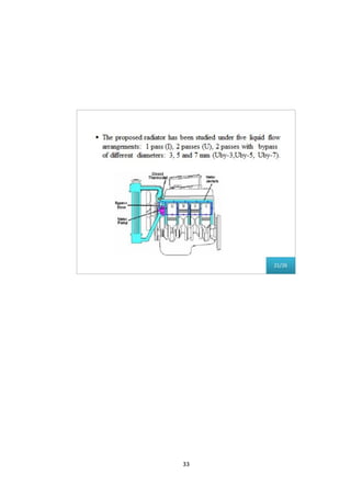
This document summarizes research on optimizing automotive radiator design. It discusses the importance of radiators in vehicle design and the need for optimization between performance, size, shape, and weight. Chapter 1 introduces the topic and Chapter 2 reviews related literature. Chapter 3 discusses the necessity of cooling systems to prevent overheating. Chapter 4 describes different radiator types. Chapter 5 reports on parametric studies examining the effects of operating conditions like air and coolant flow rates, temperatures, and coolant type on radiator performance. It also analyzes the influence of design parameters such as fin pitch, louver angle, and coolant flow layout. Figures and tables are referenced but not included.

![2
Chapter 2
LITERATURE REVIEW
Several literature related to this topic above has been referred.
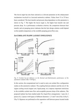
1. C. Oliet et.al [1] Parametric studies performed on automotive radiators by
means of a detailed rating and design heat exchanger model. A first part of the
analysis focuses on the influence of working conditions on both fluids (mass
flows, inlet temperatures) and the impact of the selected coolant fluid.
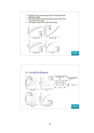
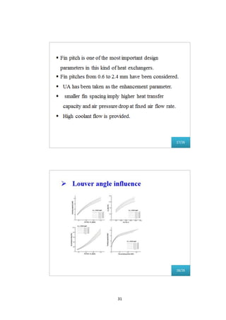
Following these studies, the influence of some geometrical parameters is
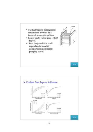
analysed (fin pitch, louver angle) as well as the importance of coolant flow
lay-out on the radiator global performance. This work provides an overall
behaviour report of automobile radiators working at usual range of operating
conditions.
2. Sudhi Uppuluri et.al [2] streamlined approach for characterizing the heat
flows from the combustion chamber to the engine coolant, engine oil circuit
and the ambient. The approach in this paper uses a built-in flow and heat
transfer solver in the CAD model of the engine to derive heat transfer
coefficients for the coolant-block interface, oil-block interface and the block-
ambient interface. These coefficients take into account the changing boundary
conditions of flow rate, temperatures, and combustion heat to help characterize
the complex thermal interactions between each of these subsystems during the
warm-up process.
3. Wei Liu et.al [3] The hydraulic retarder is the most stabilized auxiliary
braking system of heavy-duty vehicles. When the hydraulic retarder is
working during auxiliary braking, all of the braking energy is transferred into
the thermal energy of the transmission medium of the working wheel.
Theoretically, the residual heat-sinking capability of the engine could be used
to cool down the transmission medium of the hydraulic retarder, in order to
ensure the proper functioning of the hydraulic retarder. Never the less, the
hydraulic retarder is always placed at the tailing head of the gearbox, far from
the engine, long cooling circuits, which increases the risky leakage risk of the
transmission medium.](https://image.slidesharecdn.com/3rdpages-151125030728-lva1-app6892/85/SEMINAR-REPORT-2-320.jpg)
![3
4. Pallavi Annabattula et.al [4] Determining coolant flow distribution in a
topologically complex flow path for efficient heat rejection from the critical
regions of the engine is a challenge. However, with the established
computational methodology, thermal response of an engine (via conjugate heat
transfer) can be accurately predicted and improved upon via Design of
Experiment (DOE) study in a relatively short timeframe.](https://image.slidesharecdn.com/3rdpages-151125030728-lva1-app6892/85/SEMINAR-REPORT-3-320.jpg)