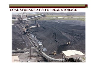
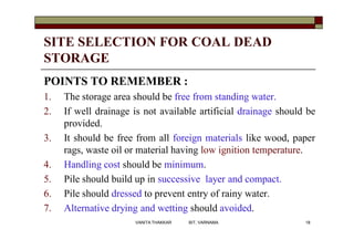
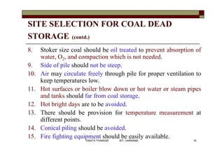
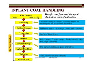
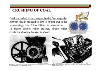
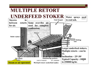
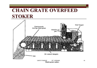
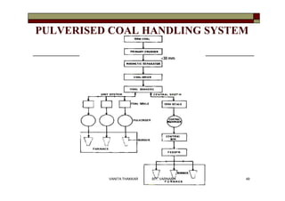
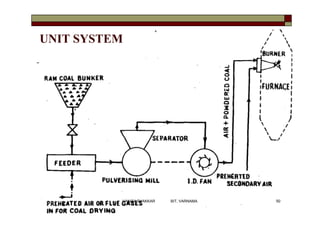
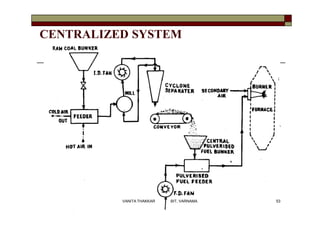
This document discusses coal handling and combustion in thermal power plants. It begins by describing the different types of coal and methods of coal analysis. It then covers various aspects of coal handling including transportation, unloading, storage, and in-plant transfer systems. Specific equipment for crushing, conveying, and elevating coal are explained. The document concludes with a discussion of coal storage, preparation plants, and solid fuel combustion using different types of stokers.
In electric power generation a combined cycle is an assembly of heat engines that work in tandem from the same source of heat, converting it into mechanical energy, which in turn usually drives electrical generators. The principle is that after completing its cycle (in the first engine), the temperature of the working fluid engine is still high enough that a second subsequent heat engine may extract energy from the waste heat that the first engine produced. By combining these multiple streams of work upon a single mechanical shaft turning an electric generator, the overall net efficiency of the system may be increased by 50â60%. That is, from an overall efficiency of say 34% (in a single cycle) to possibly an overall efficiency of 51% (in a mechanical combination of two cycles) in net Carnot thermodynamic efficiency. This can be done because heat engines are only able to use a portion of the energy their fuel generates (usually less than 50%). In an ordinary (non combined cycle) heat engine the remaining heat (e.g., hot exhaust fumes) from combustion is generally wasted.
Combining two or more thermodynamic cycles results in improved overall efficiency, reducing fuel costs. In stationary power plants, a widely used combination is a gas turbine (operating by the Brayton cycle) burning natural gas or synthesis gas from coal, whose hot exhaust powers a steam power plant (operating by the Rankine cycle). This is called a Combined Cycle Gas Turbine (CCGT) plant, and can achieve a best-of-class real (HHV - see below) thermal efficiency of around 54% in base-load operation, in contrast to a single cycle steam power plant which is limited to efficiencies of around 35â42%. Many new gas power plants in North America and Europe are of the Combined Cycle Gas Turbine type. Such an arrangement is also used for marine propulsion, and is called a combined gas and steam (COGAS) plant. Multiple stage turbine or steam cycles are also common.
This PPT contains introduction and types of thermal power plants, WORKING PRINCIPLE, LAYOUT AND WORKING OF NUCLEAR POWER PLANT, WORKING PRINCIPLE OF COAL BASED POWER PLANT, SITE SELECTION OF THERMAL POWER PLANT,GENERAL LAYOUT AND WORKING OF COAL BASED THERMAL POWER PLANT, PRESENT STATUS OF COAL-FIRED THERMAL POWER PLANT, WASTE GENERATED IN THERMAL POWER PLANTS AND MANAGEMENT , TREATMENT AND DISPOSAL OF WASTE GENERATED IN THERMAL POWER PLANTS.
Coal Fired Power Plant
-Types of coal
-Traditional coal-burning power
plant
-Emission control for traditional
coal burning plant
-Advanced coal-burning power
plant
-Environmental effects of coal
importance of coal handling system, necessity and requirement of coal handling system, various transportation means, methods and equipment's, advantages and disadvantages of various methods, coal unloading videos.
International Journal of Engineering Research and Applications (IJERA) is a team of researchers not publication services or private publications running the journals for monetary benefits, we are association of scientists and academia who focus only on supporting authors who want to publish their work. The articles published in our journal can be accessed online, all the articles will be archived for real time access.
Our journal system primarily aims to bring out the research talent and the works done by sciaentists, academia, engineers, practitioners, scholars, post graduate students of engineering and science. This journal aims to cover the scientific research in a broader sense and not publishing a niche area of research facilitating researchers from various verticals to publish their papers. It is also aimed to provide a platform for the researchers to publish in a shorter of time, enabling them to continue further All articles published are freely available to scientific researchers in the Government agencies,educators and the general public. We are taking serious efforts to promote our journal across the globe in various ways, we are sure that our journal will act as a scientific platform for all researchers to publish their works online.
Ash handling sytems in which how to handling the ash and how to used it's equipment. And also Types of the ash handling systems. or its advantage and dis advantage.
short ppt on the topic for an overview on the topic and useful for students of mechanical engineering student who have studies the ash handling system in their academics.
Karmanyevaadhikaaraste - 3 : The Caste System (ā¤ĩā¤°āĨā¤Ŗ ā¤ĩāĨā¤¯ā¤ĩā¤¸āĨā¤Ĩā¤ž) Vanita ThakkarVanita Thakkar
Â
The Caste System : a natural outcome of development of Civilizations; Challenges and Solutions - giving due importance and respect to Principles and Merits
Karmanyevaadhikaaraste -1 : Where is Krishna ? (ā¤ā¤°āĨā¤Žā¤ŖāĨā¤¯āĨā¤ĩā¤žā¤§ā¤ŋā¤ā¤žā¤°ā¤¸āĨā¤¤āĨ - 1 : ā¤āĨā¤ˇ...Vanita Thakkar
Â
A Hindi Essay / Article on Krishna - His Life, His Teachings and our understanding / perceptions .... love, relationships, Karma, religion, spirituality ....
ZAND is a village in the forests of the Panchmahals District of Gujarat.
There is a well-known, ancient Hanuman Temple at Zand.
It is believed that during their exile for twelve years after the Dyut Kreedaa (the dice game, which the Pandavas lost to the Kauravas), the Pandavas had stayed in these forests and that Shree Krishna had come to see them during their stay here.
We visited Zand on the 26th of January, 2008 â Republic Day.
The view of the Forest outside the car window was so beautiful that I could not resist the temptation to capture snaps of the passing hills, fields, villages, schools â celebrating the Republic Day, homes âĻ. in my mobile camera.
Here are those snaps âĻ. Taken while going and coming back â from the car, during the journey as well as at Zand, along with glimpses of thoughts they provoked ....
UiPath Test Automation using UiPath Test Suite series, part 3DianaGray10
Â
Welcome to UiPath Test Automation using UiPath Test Suite series part 3. In this session, we will cover desktop automation along with UI automation.
Topics covered:
UI automation Introduction,
UI automation Sample
Desktop automation flow
Pradeep Chinnala, Senior Consultant Automation Developer @WonderBotz and UiPath MVP
Deepak Rai, Automation Practice Lead, Boundaryless Group and UiPath MVP
The Art of the Pitch: WordPress Relationships and SalesLaura Byrne
Â
Clients donât know what they donât know. What web solutions are right for them? How does WordPress come into the picture? How do you make sure you understand scope and timeline? What do you do if sometime changes?
All these questions and more will be explored as we talk about matching clientsâ needs with what your agency offers without pulling teeth or pulling your hair out. Practical tips, and strategies for successful relationship building that leads to closing the deal.
LF Energy Webinar: Electrical Grid Modelling and Simulation Through PowSyBl -...DanBrown980551
Â
Do you want to learn how to model and simulate an electrical network from scratch in under an hour?
Then welcome to this PowSyBl workshop, hosted by Rte, the French Transmission System Operator (TSO)!
During the webinar, you will discover the PowSyBl ecosystem as well as handle and study an electrical network through an interactive Python notebook.
PowSyBl is an open source project hosted by LF Energy, which offers a comprehensive set of features for electrical grid modelling and simulation. Among other advanced features, PowSyBl provides:
- A fully editable and extendable library for grid component modelling;
- Visualization tools to display your network;
- Grid simulation tools, such as power flows, security analyses (with or without remedial actions) and sensitivity analyses;
The framework is mostly written in Java, with a Python binding so that Python developers can access PowSyBl functionalities as well.
What you will learn during the webinar:
- For beginners: discover PowSyBl's functionalities through a quick general presentation and the notebook, without needing any expert coding skills;
- For advanced developers: master the skills to efficiently apply PowSyBl functionalities to your real-world scenarios.
PHP Frameworks: I want to break free (IPC Berlin 2024)Ralf Eggert
Â
In this presentation, we examine the challenges and limitations of relying too heavily on PHP frameworks in web development. We discuss the history of PHP and its frameworks to understand how this dependence has evolved. The focus will be on providing concrete tips and strategies to reduce reliance on these frameworks, based on real-world examples and practical considerations. The goal is to equip developers with the skills and knowledge to create more flexible and future-proof web applications. We'll explore the importance of maintaining autonomy in a rapidly changing tech landscape and how to make informed decisions in PHP development.
This talk is aimed at encouraging a more independent approach to using PHP frameworks, moving towards a more flexible and future-proof approach to PHP development.
Smart TV Buyer Insights Survey 2024 by 91mobiles.pdf91mobiles
Â
91mobiles recently conducted a Smart TV Buyer Insights Survey in which we asked over 3,000 respondents about the TV they own, aspects they look at on a new TV, and their TV buying preferences.
Dev Dives: Train smarter, not harder â active learning and UiPath LLMs for do...UiPathCommunity
Â
đĨ Speed, accuracy, and scaling â discover the superpowers of GenAI in action with UiPath Document Understanding and Communications Miningâĸ:
See how to accelerate model training and optimize model performance with active learning
Learn about the latest enhancements to out-of-the-box document processing â with little to no training required
Get an exclusive demo of the new family of UiPath LLMs â GenAI models specialized for processing different types of documents and messages
This is a hands-on session specifically designed for automation developers and AI enthusiasts seeking to enhance their knowledge in leveraging the latest intelligent document processing capabilities offered by UiPath.
Speakers:
đ¨âđĢ Andras Palfi, Senior Product Manager, UiPath
đŠâđĢ Lenka Dulovicova, Product Program Manager, UiPath
Software Delivery At the Speed of AI: Inflectra Invests In AI-Powered QualityInflectra
Â
In this insightful webinar, Inflectra explores how artificial intelligence (AI) is transforming software development and testing. Discover how AI-powered tools are revolutionizing every stage of the software development lifecycle (SDLC), from design and prototyping to testing, deployment, and monitoring.
Learn about:
âĸ The Future of Testing: How AI is shifting testing towards verification, analysis, and higher-level skills, while reducing repetitive tasks.
âĸ Test Automation: How AI-powered test case generation, optimization, and self-healing tests are making testing more efficient and effective.
âĸ Visual Testing: Explore the emerging capabilities of AI in visual testing and how it's set to revolutionize UI verification.
âĸ Inflectra's AI Solutions: See demonstrations of Inflectra's cutting-edge AI tools like the ChatGPT plugin and Azure Open AI platform, designed to streamline your testing process.
Whether you're a developer, tester, or QA professional, this webinar will give you valuable insights into how AI is shaping the future of software delivery.
Neuro-symbolic is not enough, we need neuro-*semantic*Frank van Harmelen
Â
Neuro-symbolic (NeSy) AI is on the rise. However, simply machine learning on just any symbolic structure is not sufficient to really harvest the gains of NeSy. These will only be gained when the symbolic structures have an actual semantics. I give an operational definition of semantics as âpredictable inferenceâ.
All of this illustrated with link prediction over knowledge graphs, but the argument is general.
Transcript: Selling digital books in 2024: Insights from industry leaders - T...BookNet Canada
Â
The publishing industry has been selling digital audiobooks and ebooks for over a decade and has found its groove. Whatâs changed? What has stayed the same? Where do we go from here? Join a group of leading sales peers from across the industry for a conversation about the lessons learned since the popularization of digital books, best practices, digital book supply chain management, and more.
Link to video recording: https://bnctechforum.ca/sessions/selling-digital-books-in-2024-insights-from-industry-leaders/
Presented by BookNet Canada on May 28, 2024, with support from the Department of Canadian Heritage.
2. Coal is the main fuel used in Thermal Power
Plants across India.
TYPES OF COAL:
īŽ Peat
īŽ Lignite
īŽ Semi bituminous
īŽ Bituminous
īŽ Anthracite
INTRODUCTION
2VANITA THAKKAR BIT, VARNAMA
3. COAL ANALYSIS
Ultimate Analysis : to
determine the
constituent of coal, but
rather in a form of its
basic chemical
elements.
Constituents %
Moisture 3-30
Volatile Matter 3-50
Ash 2-30
Fixed Carbon 16-92
Constituents %
Carbon 50-95
Hydrogen 1-5.5
Oxygen 2-40
Sulpher 0.5-3
Nitrogen 0.5-7
Ash 2-30
Proximate Analysis : to
determine the amount of
fixed carbon (FC), volatile
matters (VM), moisture, and
ash within the coal sample.
3VANITA THAKKAR BIT, VARNAMA
4. RECALL :
GCV : Gross calorific value : The amount of heat released during the
combustion of a specified amount of fuel, determined by bringing
all the products of combustion back to the original pre-combustion
temperature, and in particular condensing any vapor produced.
NCV : Net calorific value : The amount of heat released during the
combustion of a specified amount of fuel, determined by
subtracting the heat of vaporization of the water vapor from the
higher heating value (GCV).
Volatile Matter: Volatile matter present in coal may be combustible
gases like CH4, H2, CO and other hydrocarbon or
incombustible gases like CO2, N2 etc. Presence of incombustible
gases is always undesirable because it reduces the GCV of the coal.
4VANITA THAKKAR BIT, VARNAMA
5. SOME IMPORTANT DEFINITIONS
Clinker : When Temperature developed in coal burning is higher than the
fusion temperature of ash, the ash melts. The melting ash engulfs the
unburnt coal particles and forms a solidified mass which is known as
clinker. It is formed while burning coal containing ash which has low
fusion temperature.
Weathering of coal: All coals tend to combine with oxygen and slow
oxidation takes place. This process of oxidation without burning is
called weathering of coal.
Primary Air: The amount of air which is used to carry the coal and to
dry it before entering into the combustion chamber is known as
âPrimary Airâ
Secondary Air: The amount of air which is supplied separately for
completing the combustion is known as âSecondary Airâ.
5VANITA THAKKAR BIT, VARNAMA
6. OUT-PLANT HANDLING OF COAL
Out plant handling means transfer of coal from
mine or port to storage of coal at plant site
(dead storage).
1. Transportation by Rail: 4000 TO 13000 TONS PER TRIP.
2. Transportation by Ropeways
3. Transportation by Transportation by Sea or River
4. Road
5. Transportation of coal by Pipeline
6VANITA THAKKAR BIT, VARNAMA
11. COAL STORAGE
Storage of coal is undesirable,
because it costs more as there
is
īŽ risk of spontaneous
combustion,
īŽ weathering,
īŽ possibility of loss and
deterioration during storage,
īŽ interest on capital cost of coal
lying dormant,
īŽ cost of protecting the stored
coal from deterioration
and so on. 11VANITA THAKKAR BIT, VARNAMA
12. TYPES OF COAL STORAGE
ī¯ Dead Storage :
īŽ Supplies the coal where there is a shortage of
coal in plant due to failure of normal supply
of coal.
īŽ This is long term storage and 10% of annual
consumption, so it requires protection
against weathering and spontaneous
combustion. 12VANITA THAKKAR BIT, VARNAMA
13. TYPES OF COAL STORAGE
ī¯ Live storage :
īŽ Supplies coal to plant for day to day usage.
Capacity of live storage is less then that of dead
storage.
īŽ Usually stored in vertical cylindrical bunkers or
coal bins or silo, from where coal is transferred to
boiler grate.
īŽ Bunkers are normally diamond-shaped cross-
section storage area, made up of steel or
reinforced concrete. 13VANITA THAKKAR BIT, VARNAMA
14. PURPOSE OF DEAD STORAGE OF
COAL
ī¯ To prevent shutdown of power plant in case
of failure of normal supplies of coal due to
coal strike, failure of the transport system etc.
ī¯ Storage permits choice of the date of purchase
allowing management to take advantage of
seasonal market conditions.
14VANITA THAKKAR BIT, VARNAMA
15. MEANS OF COAL STORAGE
Storage in Coal Heaps :
It is required to :
īŽ Keep coal at low temperature (>70ÂēC)
īŽ Prevention of air circulation from bottom of coal piles
īŽ Proper drainage of rainy water to prevent weathering â drainage
should not be rapid to prevent washing away of coal.
Hence, ground used for stocking should be dry and leveled for
proper drainage and concrete-floored to prevent flow of air
from bottom.
Coal is piled at a height of about 10 to 12 m and compacted in
layers of 15 to 30 cm.
In dead storage, coal pile is sealed by asphalt, fine coal dust,
bituminous coating or other coating material.
15VANITA THAKKAR BIT, VARNAMA
16. MEANS OF COAL STORAGE (contd.)
Underwater Storage :
Possibility of slow oxidation and
spontaneous combustion can be
completely eliminated by storing coal
under water.
16VANITA THAKKAR BIT, VARNAMA
17. COAL STORAGE AT SITE : DEAD STORAGE
17VANITA THAKKAR BIT, VARNAMA
18. SITE SELECTION FOR COAL DEAD
STORAGE
POINTS TO REMEMBER :
1. The storage area should be free from standing water.
2. If well drainage is not available artificial drainage should be
provided.
3. It should be free from all foreign materials like wood, paper
rags, waste oil or material having low ignition temperature.
4. Handling cost should be minimum.
5. Pile should build up in successive layer and compact.
6. Pile should dressed to prevent entry of rainy water.
7. Alternative drying and wetting should avoided.
18VANITA THAKKAR BIT, VARNAMA
19. SITE SELECTION FOR COAL DEAD
STORAGE (contd.)
8. Stoker size coal should be oil treated to prevent absorption of
water, O2, and compaction which is not needed.
9. Side of pile should not be steep.
10. Air may circulate freely through pile for proper ventilation to
keep temperatures low.
11. Hot surfaces or boiler blow down or hot water or steam pipes
and tanks should far from coal storage.
12. Hot bright days are to be avoided.
13. There should be provision for temperature measurement at
different points.
14. Conical piling should be avoided.
15. Fire fighting equipment should be easily available.
19VANITA THAKKAR BIT, VARNAMA
20. INPLANT COAL HANDLING
Coal Delivery
Road Rail & Ship
Unloading
Preparation
Transfer
Inplant Handling
Weighting
Furnace Fire
Car shakers, Rotary car dampers, unloading bridges, Self
unloading ship, lifts trucks cranes and buckets.
Crushers, Sizers, driers
Belt conveyers, Screw conveyers, Bucket elevator, skip
hoist, flight conveyers.
Bulldozers, scrapers, tramways, cranes and conveyers.
Bins, bunkers, indicators, gates, and valves.
Scales, coal meters and samplers.
Covered storage
Outdoor Storage
InPlantHandling
Transfer coal from coal storage at
plant site to point of utilization.
20VANITA THAKKAR BIT, VARNAMA
21. DESIGN OF INPLANT COAL HANDLING
SYSTEM
POINTS TO REMEMBER :
1. Simple and sound, requiring minimum operations and
transportation.
2. No double handling of coal in plant.
3. Handling unit should be centralized to facilitate inspection
and maintenance.
4. Electric motors can be used as driver of mechanism.
5. Working parts should be enclosed to avoid abrasion and
corrosion.
6. System should be able to supply required quantity of coal as
per demand.
21VANITA THAKKAR BIT, VARNAMA
25. CRUSHING OF COAL
Coal is crushed in two stages. In the first stage the
300mm size is reduced to 100 to 75mm and in the
second stage from 75 to 100mm to below 6mm.
In figure double roller crusher, single roller
crusher and rotary breaker is shown.
25VANITA THAKKAR BIT, VARNAMA
26. VIBRATING SEPARATOR
Sizer or vibrating separator is fitted after crusher to screen the coal
crushed below set size. Over size coal is returned to crusher for
further proper crushing. Generally it separates out oversize coal of
size > 6mm.
26VANITA THAKKAR BIT, VARNAMA
27. TRANSFER OF COAL
Equipments used in coal transfer are:
īŽ Belt Conveyer
īŽ Flight Conveyer
īŽ Screw Conveyer
īŽ Bucket Elevator
īŽ Grab Bucket Elevator
īŽ Skip Hoists
27VANITA THAKKAR BIT, VARNAMA
28. BELT CONVEYORS
A very suitable means of
Transporting, it can transfer
large quantity of coal over large
distance economically â low
initial cost, low power
consumption. Main parts are:
Belt (made of rubber, canvas or
balata)
End Drums or pulleys
Idlers
Return Idlers
28VANITA THAKKAR BIT, VARNAMA
29. BELT CONVEYORS (contd.)
It uses inclination upto 20Âē
Avg. speed : 60 to 100 m/min
Capacity : 50 to 100 tones/hr
Max distance it can transfer : 400m
Advantage:
ī¯ Economical, Low power consumption.
ī¯ Large capacity
ī¯ Rate of coal transfer rapidly change
ī¯ Low maintenance cost.
Disadvantage:
ī¯ Not suitable for shorter distance and
inclination >20Âē
ī¯ Not suitable for dust particles and slurry. 29VANITA THAKKAR BIT, VARNAMA
30. FLIGHT CONVEYER (SCRAPER)
īŽ It is used when coal is discharged at different points in
bins situated below the conveyer.
īŽ All parts are made of steel and iron, so it can handle hot
material.
īŽ It is totally enclosed, so dust of coal can get transferred.
īŽ It can transfer coal at high inclination.
30VANITA THAKKAR BIT, VARNAMA
31. FLIGHT CONVEYER (SCRAPER) (contd.)
Advantages:
ī¯ It requires small head room
ī¯ Speed and so material transfer rate
can easily change.
ī¯ It can handle hot materials also.
Disadvantages:
ī¯ High wear and tear, so short life.
ī¯ High maintenance required.
ī¯ Speed is limited up to 300 m/min due to abrasive action of
material.
ī¯ High power consumption per unit of material transfer. 31VANITA THAKKAR BIT, VARNAMA
32. SCREW CONVEYOR
ī¯ It is used for shorter distance.
ī¯ Totally enclosed from atmosphere.
ī¯ Coal dust can also be transferred
easily.
ī¯ It is generally used in metering of
coal.
ī¯ Driving mechanism is attached at
end of the shaft.
ī¯ Diameter : 15 cm to 50 cm.
ī¯ Speed : 70 to 120 rpm.
ī¯ Capacity : 125 tones/hr (max.).
32VANITA THAKKAR BIT, VARNAMA
33. SCREW CONVEYOR (contd.)
Advantage:
īŽ Cheap initial cost.
īŽ Simple and compact
īŽ Dust tight.
īŽ It can transfer coal at high
inclination also.
īŽ Most suitable for short
distance.
Disadvantage:
īŽ High power consumption.
īŽ Length is limited up to 30 m
īŽ High maintenance due to
high wear and tear. 33VANITA THAKKAR BIT, VARNAMA
34. Centrifugal Type
Continuous Type
Height: 30.5 m max.
Inclination with Vertical: 30Âē
Chain speed :
Centrifugal: 75 m/min
Continuous: 35 m/min
Capacity: 60 tones/hr
BUCKET ELEVATOR
ī¯ It is used for vertical
lifts.
ī¯ Buckets are fixed on
chain which moves on
two wheels or
sprockets.
ī¯ Buckets are loaded at
bottom and
discharged at top.
ī¯ Continuous Type
Bucket capacity is
more than that of
Centrifugal type.
34VANITA THAKKAR BIT, VARNAMA
35. GRAB BUCKET ELEVATOR
ī¯ It is used for lifting as well as
transfer.
ī¯ It can be used with crane or
tower.
ī¯ Initial cost is high but
operation cost is less.
ī¯ It is used when another
arrangement is not possible.
ī¯ Bucket capacity : 2 to 3 m3
ī¯ Distance : 60 m
ī¯ Capacity : 100 tones/hr.
35VANITA THAKKAR BIT, VARNAMA
36. COAL BURNING SYSTEM
ī¯ FURNACE : Confined space where fuel is
burnt. Provides supports and enclosure for
burning equipment.
ī¯ For solid fuels, like coal, coke, wood, etc. :
STOKERS to convey the coal, GRATE to hold
the fuel.
ī¯ For pulverized coal and liquid fuels :
BURNERS.
36VANITA THAKKAR BIT, VARNAMA
37. SOLID FUEL FIRING
ī¯ HAND FIRING :
īŽ Simple method.
īŽ No capital investment.
īŽ Used for smaller plants.
īŽ Not a continuous firing process.
īŽ Only very small furnaces can be fired by this
method.
īŽ Poor response to load fluctuations.
īŽ Controlling draught is difficult.
37VANITA THAKKAR BIT, VARNAMA
38. SOLID FUEL FIRING (contd.) : MECHANICAL
FIRING / STOKER FIRING (Medium and large size
plants.)
ADVANTAGES :
ī¯ High combustion
efficiency.
ī¯ No coal preparation.
ī¯ Low grade coal can be
used.
ī¯ Reliable firing system.
ī¯ Less labour requirement.
ī¯ Less smoke produced.
ī¯ Minimum danger of
explosion.
DISADVANTAGES :
ī¯ High initial cost.
ī¯ Complicated construction.
ī¯ Coal loss in moving through
grates.
ī¯ High maintenance/repair cost
due to high furnace
temperatures.
ī¯ Excessive wear of moving parts
by abrasive action of coal.
ī¯ Difficult : Sudden variations in
steam demand.
38VANITA THAKKAR BIT, VARNAMA
39. TYPES OF STOKERS : based on
way of feeding coal on grate
OVERFEED STOKER :
ī¯ Coal is fed from above, air from
bottom.
ī¯ Layers from above (after
flame):
īŽ Fresh Coal Zone.
īŽ Drying Zone.
īŽ Distillation Zone â losing
volatile content.
īŽ Combustion Zone â
incandescent coke.
īŽ Ash Zone.
UNDERFEED STOKER :
ī¯ Coal and air are fed from
bottom.
ī¯ Layers from bottom :
īŽ Green Coal.
īŽ Ignition Zone (VM + CO
+ CO2 + N2 + H2).
īŽ Incandescent coke (CO2 +
O2 + N2 + H2O).
īŽ Ash .
īŽ Flame. 39VANITA THAKKAR BIT, VARNAMA
40. SINGLE RETORT UNDERFEED
STOKER âĸ Smaller size / capicity.
âĸ Screw feeder on a
mechanical ram forces the
coal upward along the
length.
âĸ Typical capacity : 1500 to
15000 kg/hr.
Troughs
for
feeding
coal Openings
for air 40VANITA THAKKAR BIT, VARNAMA
41. MULTIPLE RETORT
UNDERFEED STOKER
Larger underfeed stokers.
Multiple retorts â can be
12.
Inclination â 25o-30o
Typical Capacity : 10000
to 250000 kg/hr.
Some over-fire air
used for complete
combustion.
Tuyeres in
between retorts
for air.
Some over-fire air
used for complete
combustion.
Steam or air operated
Water sprays used
to cool ash.
41VANITA THAKKAR BIT, VARNAMA
42. ADVANTAGES OF MULTIPLE
RETORT UNDERFEED STOKERS
ī¯ High combustion efficiency.
ī¯ High part-load efficiency.
ī¯ Self-cleaning grate.
ī¯ Smokeless operation at even very high loads.
ī¯ High combustion rate.
ī¯ Grate bars, tuyeres and retorts not subjected high
temperatures due to continuous contact with fresh coal.
ī¯ Substantial amount of coal remains on grate ī boiler
remains in service during temporary breakdown.
ī¯ Different varieties of coals can be used. 42VANITA THAKKAR BIT, VARNAMA
43. DISADVANTAGES OF MULTIPLE
RETORT UNDERFEED STOKERS
ī¯ High initial cost.
ī¯ Larger space requirements.
ī¯ Clinker formation not eliminated.
ī¯ High rate of wear and tear due to moving parts.
ī¯ Low grade fuels with high ash contents cannot be
burnt economically.
43VANITA THAKKAR BIT, VARNAMA
45. ADVANTAGES OF CHAIN GRATE
OVERFEED STOKERS
ī¯ Simple in construction.
ī¯ Low maintenance cost.
ī¯ Low initial cost.
ī¯ Self-cleaning stoker.
ī¯ Heat release rates can be controlled by
controlling the speed of chains. 45VANITA THAKKAR BIT, VARNAMA
46. DISADVANTAGES OF CHAIN
GRATE OVERFEED STOKERS
ī¯ Always some loss of coal by fine particles carried
with ashes.
ī¯ Temperature of preheated air limited to 180oC.
ī¯ Not suitable for high capacity boilers (200 tonnes/hr
or more) as small amount of coal is carried in the
grate.
ī¯ Clinker problem â common. 46VANITA THAKKAR BIT, VARNAMA
51. ADVANTAGES OF UNIT SYSTEM
īŽ It is simple in layout and cheaper than central system.
īŽ The coal transportation system is simple.
īŽ It allows direct control of combustion from the pulverize.
īŽ The maintenance charges are less as spares required are
less.
īŽ In the replacement of stokers, the old conveyor system can
be used without much alteration.
īŽ Coal which requires drying for satisfactory function of the
central system is generally supplied without drying in the
unit system.
īŽ It affords better control of fuel feed into the boiler
furnace.
51VANITA THAKKAR BIT, VARNAMA
52. DISADVANTAGES OF UNIT SYSTEM
īŽ The mill operates at variable load as per the load on the power
plant which results in poor performance of the pulverising mill
(more power consumption per ton of coal at part load).
īŽ The total capacity of all mills must be higher than that for the
central system with the load factors common in practice.
īŽ The degree of flexibility is less than of central system.
īŽ The fault in the preparation unit may put the entire steam
generator out of use because no storage of pulverize coal.
īŽ Strict maintenance is desired as the operation of the plant directly
depends upon the pulverizing mill.
īŽ There is excessive wear and tear of the primary fan blades as it
handles air and coal particles.
52VANITA THAKKAR BIT, VARNAMA
54. ADVANTAGES OF CENTRALIZED
SYSTEM
ī¯ Central system is flexible and changes can be made to
accommodate quick changes in demand.
ī¯ There is always a supply of fuel available in reserve in the boiler
bunkers.
ī¯ Since any mill can be used to supply to any boiler, the outage of
parts of the mills or even a short outage of entire pulverizing plant
will not cause a boiler plant outage.
ī¯ Pulverizer mills always runs at its rated load irrespective of the
load on the plant, therefore its power consumption per ton of coal
crushed per hour is less and capacity of mill required less
comparatively.
54VANITA THAKKAR BIT, VARNAMA
55. ADVANTAGES OF CENTRALIZED
SYSTEM (contd.)
ī¯ Pulverizer can be shutdown when sufficient reserve capacity
has been achieved. During peak load, this reserve capacity
can fulfill excess demand of coal.
ī¯ Good control over fineness of coal.
ī¯ There is greater degree of flexibility as the quantity of fuel
and air can be separately controlled.
ī¯ Burners can be operated independently of the operation of
coal preparation.
ī¯ Primary fan can handle only air so no problem of excessive
wear of blades.
ī¯ More flexibility of fitting of burners.
55VANITA THAKKAR BIT, VARNAMA
56. DISADVANTAGES OF
CENTRALIZED SYSTEM
ī¯ Higher initial cost and
ī¯ Occupies a large space due bulky storage bin
ī¯ High auxiliary power consumption. So power
consumption/ton of coal is more then unit system
ī¯ Possibility of fire hazard due to the storage of
pulverized coal.
ī¯ Complex coal transportation system.
ī¯ Driers are essential.
56VANITA THAKKAR BIT, VARNAMA
57. DISADVANTAGES OF
CENTRALIZED SYSTEM (contd.)
ī¯ Operation and maintenance cost are higher
then unit system.
Note: bin system is not adopted in large capacity
plants because of dangers from EXPLOSION of
coal air mixture and tendency of stored
pulverized fuel to cake. Also it required more
maintenance, losses of coal through vent, high
initial cost, high operating cost.
So universally Unit System is adopted for large
capacity power plants.
57VANITA THAKKAR BIT, VARNAMA
59. 1.Ball mill
2.Ball and Race mill
3.Impact or hammer mill
4.Bowl mill
59VANITA THAKKAR BIT, VARNAMA
60. BALL MILL
Sharp
changes in the
direction of
the mixture
throws out
over-sized
particles
(returned to
drum)
10 tons of coal
per hour with
4% moisture
requires 28
tones of steel
balls. There is
20-25kWh
energy
consumption
per ton of coal.
60VANITA THAKKAR BIT, VARNAMA
61. ADVANTAGES OF BALL MILL
ī¯ Simple operation.
ī¯ Low initial cost.
ī¯ Grinding elements are not seriously
affected by metal scrap and other foreign
material in the coal.
ī¯ Suitable for wide range of fuels, including
anthracite and bituminous coal.
ī¯ Low maintenance cost.
61VANITA THAKKAR BIT, VARNAMA
62. DISADVANTAGES OF BALL MILL
ī¯ Large and heavy in construction.
ī¯ Consumes more power than other mills.
ī¯ Poor air circulation, so works less
efficiently with wet coals.
ī¯ High operating cost.
62VANITA THAKKAR BIT, VARNAMA
63. BALL AND RACE MILL
Rotating.
Hold down upper race
to adjust force needed
for crushing
Very widely
used.
Principle of operation : Crushing
and attrition.
63VANITA THAKKAR BIT, VARNAMA
64. ADVANTAGES / DISADVANTAGES OF
BALL AND RACE MILL
ADVANTAGES :
ī¯ Low power consumption.
ī¯ Lower weight.
ī¯ Lower initial cost.
ī¯ Lower operating cost.
ī¯ Suitable for variable load
conditions.
ī¯ Can handle coals
containing as much as 20%
moisture.
DISADVANTAGES :
ī¯ Greater wear
compared to other
pulverizers.
ī¯ Leakage of fine
coal through the
mill.
64VANITA THAKKAR BIT, VARNAMA
66. ADVANTAGES / DISADVANTAGES OF
BOWL MILL
ADVANTAGES :
ī¯ Lower energy consumption
(12-15kWh/t)
ī¯ Less overall dimensions.
ī¯ Classifier can be adjusted to
alter degree of coal fineness
while mill is on.
ī¯ Leakage of coal from mill
casing is practically nil as it
operates at negative
pressure.
ī¯ Less noisy.
DISADVANTAGES :
ī¯ Sensitive to metallic
objects that enter
with coal.
ī¯ Uneven wear of
grinding parts
presents repairing
complexities.
66VANITA THAKKAR BIT, VARNAMA
67. IMPACT OR HAMMER MILL
For brown coals, peat, oil
shales, etc.
67VANITA THAKKAR BIT, VARNAMA
68. ADVANTAGES / DISADVANTAGES OF
HAMMER / IMPACT MILL
ADVANTAGES :
ī¯ Simple construction.
ī¯ Low capital cost.
ī¯ Requires minimum
floor area.
ī¯ Operational speed is
high.
ī¯ Wet coal can be
pulverized.
DISADVANTAGES :
ī¯ High power
consumption when
fine coal is require.
ī¯ Limited capacity.
ī¯ Metal scrap cannot
be allowed to enter
the mill.
68VANITA THAKKAR BIT, VARNAMA
69. PULVERISED COAL BURNERS
REQUIREMENTS:
ī¯ Proper mixing of coal and primary air.
ī¯ Bring mixture of coal and primary air in contact
with secondary air to create sufficient
turbulence.
ī¯ Controlling of flame shape and flame travel.
ī¯ Adequate protection against overheating and
excessive abrasive wear.
ī¯ Ensure complete combustion. 69VANITA THAKKAR BIT, VARNAMA
70. PULVERISED COAL BURNERS
FACTORS AFFECTING PERFORMANCE :
ī¯ Characteristics of fuel used.
ī¯ Particle size of pulverized coal.
ī¯ Mixing of air and fuel.
ī¯ Proportions of primary and secondary air.
ī¯ Volatile matter content in coal.
ī¯ Furnace design.
70VANITA THAKKAR BIT, VARNAMA
72. LONG FLAME/U-FLAME BURNER
ī¯ Primary, secondary and tertiary air
required for combustion.
ī¯ Hot secondary air is introduced at right
angles to the flame for necessary mixing for
better and rapid combustion.
ī¯ Flame travels longer to allow it to get
sufficient time for complete combustion.
ī¯ Used for low volatile coal.
72VANITA THAKKAR BIT, VARNAMA
73. SHORT FLAME / TURBULENT
BURNER
ī¯ Fire horizontally or at some inclinations by
adjustments.
ī¯ High turbulence is created for pulverized coal
and hot secondary air going to the burner ī
mixture burns as soon as it enters ī
combustion completed in a short distance.
ī¯ Generally preferred for high volatile coals.
ī¯ All modern power plants generally use it.
73VANITA THAKKAR BIT, VARNAMA
74. TANGENTIAL BURNER
ī¯ High heat release rates.
ī¯ Simple operation.
ī¯ Almost complete
combustion can be
achieved.
ī¯ Liquid, gaseous or
pulverized fuels can be
readily burnt either
separately or in
combination.
ADVANTAGES :Four burners located in four
corners of the furnace.
Fires in such a way that four
flames are tangential to an
imaginary circle formed at
the centre.
74VANITA THAKKAR BIT, VARNAMA
77. CYCLONE BURNER
ī¯ Water-cooled horizontal cylinder.
ī¯ Located outside main boiler furnace.
ī¯ Crushed coal is fed and fired with high rates of
heat release.
ī¯ Coal combustion is complete before the
resulting hot gases enter the furnace.
ī¯ High temperature â about 2000oC is developed.
ī¯ The liquid slag formed is discharged off.
77VANITA THAKKAR BIT, VARNAMA
78. ADVANTAGES OF CYCLONE
BURNER
ī¯ Crushed coal is used. So, no pulverizing equipment.
ī¯ Removes most of the ash, about 60% as molten slag.
Hence, only 40% of the ash leaves with flue gases (in
pulverized coal firing, 80% of ash goes with flue
gases).
ī¯ Reduces erosion and fowling of steam generator
surface due to low ash content in flue gases.
ī¯ Best results in low grade fuels like Indian Coal.
ī¯ Can be operated with less excess air.
ī¯ High furnace temperature obtained. 78VANITA THAKKAR BIT, VARNAMA
79. DISADVANTAGES OF CYCLONE
BURNER
ī¯ High F. D. Fan pressure required ī high
power consumption.
ī¯ Formation of relatively more NOx, which
pollutes air.
ī¯ Not suitable for high Sulphur content coal.
79VANITA THAKKAR BIT, VARNAMA
80. OIL BURNERS
ī¯ Functions :
īŽ Mixing oil and air in proper proportions.
īŽ Prepare fuel for combustion.
ī¯ Generally used in small capacity boilers
for industrial process heating.
ī¯ It has to prepare air-oil mixture requiring
minimum excess air for achieving
maximum temperatures. 80VANITA THAKKAR BIT, VARNAMA
82. TYPES OF OIL BURNERS
ī¯ VAPOURIZING BURNERS :
īŽ Oil is vapourized / gasified by heating within the
burner.
īŽ Used in blow torches, gasoline stoves, etc.
īŽ Not used in boilers for steam generation.
ī¯ ATOMIZING BURNERS :
īŽ Oil is atomized by nozzle(s) and vapourization
occurs in combustion space.
īŽ Used in oil-fired furnaces and boiler furnaces. 82VANITA THAKKAR BIT, VARNAMA
83. STEAM OR HIGH PRESSURE AIR
ATOMIZING BURNERS
ī¯ VAPOURIZING BURNERS :
īŽ Oil is vapourized / gasified by heating within the
burner.
īŽ Used in blow torches, gasoline stoves, etc.
īŽ Not used in boilers for steam generation.
ī¯ ATOMIZING BURNERS :
īŽ Oil is atomized by nozzle(s) and vapourization
occurs in combustion space.
īŽ Used in oil-fired furnaces and boiler furnaces. 83VANITA THAKKAR BIT, VARNAMA
84. TYPICAL OIL BURNER Preheated Oil (93oC-
120oC) delivered under
pressure through a tube.
Steam or air supplied by
annular area between oil pipe
and concentric outer tube.
Oil is broken down into small droplets
by using air or steam under pressure.
84VANITA THAKKAR BIT, VARNAMA
85. MECHANICAL BURNER
ī¯ Oil is pressurized by :
īŽ Positive displacement pump.
īŽ Centrifugal dispersal of oil from a rotating wheel.
ī¯ Spray nozzle is used for oil injection under high
pressure of about 25 to 35 bar.
ī¯ The oil leaves the nozzle in atomized state.
ī¯ Rotating Wheel Burner : Oil leaves orifice as hollow
cone of fine fuel particles due to centrifugal action.
ī¯ Widely used due to less auxiliary consumption and
less excess air required. 85VANITA THAKKAR BIT, VARNAMA
90. Mechanical AHS : Hot ash
coming from boiler falls on a
belt conveyor through a water
seal â gets cooled on quenching
â and is carried continuously by
conveyor to ash bunker or
dumping site.
90VANITA THAKKAR BIT, VARNAMA
91. ADVANTAGES / DISADVANTAGES OF
MECHANICAL AHS :
ADVANTAGES :
ī¯ Low power
consumption.
ī¯ Continuous ash
removal.
DISADVANTAGES :
ī¯ Suitable for coal-
fired, low capacity
plants.
ī¯ Maximum capacity :
5t/h.
ī¯ Short life span : 5-
10 years only.
91VANITA THAKKAR BIT, VARNAMA
92. Low Velocity Hydraulic AHS :
Ash from furnace grate falls
into a low velocity water
channel (3 to 5 m/s) and goes to
ash sumps. There, ash and
water are separated. Water is
reused.
Capacity : 50t/h
Distance : 500m
92VANITA THAKKAR BIT, VARNAMA
93. High Velocity Hydraulic AHS :
Hoppers below boiler are fitted
with nozzles on top (to quench
ash) & sides (to drive ash).
Cooled ash goes to water
channel below, settles & is
removed. Water reused.
Capacity : 120t/h
Distance : 1km
PCBs use it.
93VANITA THAKKAR BIT, VARNAMA
94. ADVANTAGES OF HYDRAULIC
AHS :
ī¯ High capacity, so more suitable for modern
large capacity thermal power plants.
ī¯ Clean and dust-free operation.
ī¯ Ash can be disposed upto a distance of 1km
from the TPP.
ī¯ Can also handle molten ash.
ī¯ No moving parts in contact with ash. Hence
erosion problem is minimum.
94VANITA THAKKAR BIT, VARNAMA
95. ADVANTAGES OF HYDRAULIC
AHS :
ī¯ Abrasive ash forms corrosive acids
in contact with water.
ī¯ Water channel and pump must be
made of special wear resisting
material. 95VANITA THAKKAR BIT, VARNAMA
96. PNEUMATIC AHS :
ī¯ High velocity air steam is directed to collect ash and dust
from all discharge points.
ī¯ All collected ash â crushed on the way by crushers, if
clinkers are present â drops into air stream.
ī¯ Cyclone separators separate ash from air.
ī¯ Ash is collected in hoppers for further handling for
disposal by trucks.
ī¯ Clean air is discharged from top of secondary air
separator into atmosphere through exhauster.
ī¯ Typical Ash handling capacity : 5 to30 t/h 96VANITA THAKKAR BIT, VARNAMA
99. ADVANTAGES OF PNEUMATIC
AHS :
ī¯ Dust-free operation.
ī¯ No re-handling problem.
ī¯ Dry ash handling eliminates chances of ash
freezing, picking or sticking to storage bins.
ī¯ Flexibility in operation to suit various plant
conditions.
ī¯ Installation cost per ton of ash handled is less
than that in other systems.
99VANITA THAKKAR BIT, VARNAMA
100. DISADVANTAGES OF PNEUMATIC
AHS :
ī¯ Noisy operation.
ī¯ Wearing of crusher and pipe
lines by abrasive ash inflicts high
maintenance cost.
100VANITA THAKKAR BIT, VARNAMA
101. STEAM JET AHS :
ī¯ High steam jet is passed through a pipe to
carry off dust and ash particles, instead of air
stream.
ī¯ Ash is separated in cyclone separator and
deposited into ash hopper for further
disposal by trucks. 101VANITA THAKKAR BIT, VARNAMA
102. ADVANTAGES / DISADVANTAGES OF
STEAM JET AHS :
ADVANTAGES :
ī¯ No auxiliary drive
required.
ī¯ Less capital cost.
ī¯ Less space required.
ī¯ Installed at inaccessible /
awkward positions also.
ī¯ Economical for ash disposal
â 200m horizontal distance,
30m vertical distance.
DISADVANTAGES :
ī¯ Noisy operation.
ī¯ Erosion in
pipelines due to
abrasive ash.
ī¯ Capacity limited
to 5t/h.
102VANITA THAKKAR BIT, VARNAMA
104. DUST COLLECTORS â WHY ?
ī¯ Flue gas exhaust contains fly ash.
ī¯ Flue gas exhaust in pulverized coal fired
boilers contains 80% of ash content of
coal.
ī¯ Fly ash is very fine â most of the
particles can pass through a 300 mesh
(40m) screen â particle size varies from
1m to 80m â basic difficulty in handling.104VANITA THAKKAR BIT, VARNAMA
105. DUST COLLECTORS â WHY ?
(contd.)
ī¯ Fly ash pollutes atmosphere â harms human,
animal and plant health.
ī¯ So, concentration of fly ash in flue gas must be
brought down to below 0.5 g/m3, before
discharging into atmosphere.
ī¯ High ash content in Indian coals â about 25% -
50%.
ī¯ A 200 MW plant using pulverized coal produces
about 250T of fly ash per day. 105VANITA THAKKAR BIT, VARNAMA
106. BASIC REQUIREMENTS OF GOOD
DUST COLLECTOR
ī¯ Ability to remove very fine fly ash particles.
ī¯ Low capital cost.
ī¯ Low operating and maintenance costs.
ī¯ Good wear resistance against erosion caused
by abrasive fly ash.
ī¯ Minimum floor space requirement.
ī¯ High efficiency at all load conditions.
106VANITA THAKKAR BIT, VARNAMA
107. TYPES OF DUST COLLECTORS
1. MECHANICAL DUST COLLECTORS :
1. DRY TYPE
1. GRAVITATIONAL
2. CYCLONE
2. WET TYPE
1. SPRAY TYPE SCRUBBERS
2. PACKED BED SCRUBBERS
3. IMPINGEMENT TYPE SEPARATORS
2. ELECTROSTATIC PRECIPITATORS 107VANITA THAKKAR BIT, VARNAMA
108. GRAVITATIONAL SEPARATORS :
Work on principle of gravity.
Advantages :
âĸSimple.
âĸLow capital and maintenance
costs.
Disadvantages :
âĸCannot remove fine particles.
âĸBulky.
âĸLarge space requirement.
108VANITA THAKKAR BIT, VARNAMA
109. CYCLONE DUST COLLECTOR
Commonly used
for stoker as well
as pulverized fuel
firing.
Efficiency range :
60% - 90%.
109VANITA THAKKAR BIT, VARNAMA
110. CYCLONE DUST COLLECTORS
(CONTD.)
Advantages :
1. High efficiency for large size
particles.
2. Low maintenance cost.
3. Simple, cheap and easy operation.
4. Increase in efficiency with
increasing load.
Disadvantages :
1. Efficiency decreases with fineness
of particles.
2. High power requirement for
higher vortex velocity of flue gases.
3. Large space requirement.
4. High pressure loss. 110VANITA THAKKAR BIT, VARNAMA
111. WET TYPE MECHANICAL DUST
COLLECTOR (WET SCRUBBER)
Principle : Fly ash and sulphur
present in outgoing flue gases is
removed by water spraying â as
shown in the fig.
To minimize corrosion
problems, tank is lined with
lead, pipes are lined with rubber
and spray nozzles are made of
vitrified material.
Advantage : High efficiency
(about 90%).
Disadvantage : Large water
consumption & Corrosion.
Tangential
entry
111VANITA THAKKAR BIT, VARNAMA