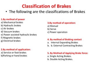
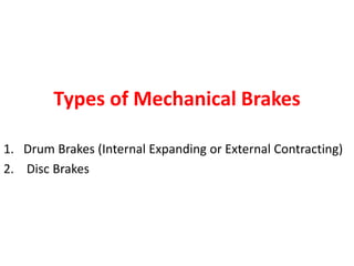
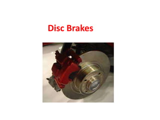
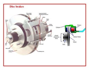
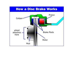
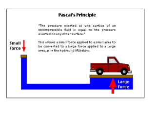
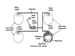
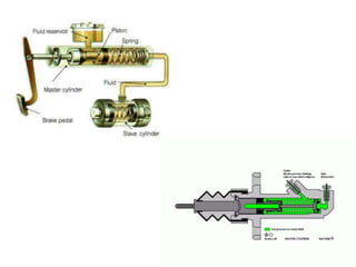
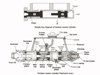
Classification of Brakes
• The following are the classifications of Brakes
1.By method of power
a) Mechanical brakes
b) Hydraulic brakes
c) Air brakes
d) Vacuum brakes
e) Power assisted hydraulic brakes
f) Magnetic brakes
g) Electrical brakes
2.By method of application:
a) Service or foot brakes
b)Parking or hand brakes
3.By method of operation:
a) Manual
b) Servo
c) Power operation
4. By method of Braking contact
a. Internal Expanding Brakes
b. b. External Contracting Brakes
5. By Method of Applying Brake force:
a. Single Acting Brakes.
b. Double Acting Brakes.
Types of Mechanical Brakes
1. Drum Brakes (Internal Expanding or External Contracting)
2. Disc Brakes
Drum Brakes
The main components of drum brakes are
1. Brake drum
2. Back plate
3. Brake shoes
4. Brake Liners
5. Retaining Springs
6. Cam
7. Brake Linkages
Drum Brakes
•In this system the wheel is attached to drum.
• There are brake shoes used to contact the rotating drum for braking
operation.
• The shoes provide lining on their outer surface.
• The cam is used to lift the brake shoes at one end, other end is
connected by some method so as to make as the brake sleeve come into
contact in the brake drum.
•The retaining spring is provided for bringing the brake shoes back to its
original position, after releasing the brake pedal.
•All these parts are fitted in the back plate and enclosed with brake
drum.
Construction:
Working:
• When the pedal is pressed the cam moves the
shoes outwards through linkages, there by coming
in frictional contact with the rotating drum.
• As soon as the brake pedal is released the retaining
springs help the brake shoes to brought back and
release the brakes.
Disc Brakes
Disc Brakes
1.Connecting tube
2. Cylinder
3. Piston
4. Friction pad
5. Hydraulic fluid
6. Brake disc
7. From master cylinder
8. Caliper
Components of disc brakes
1. Disc
2. Calipers
3. Friction Pads
Disc
• It is made of high-grade of gray cast iron having
pearlitic structure to give better wear resistance
property.
• This disc, which rotates with the car wheel, is
efficiently cooled as most of its area lies
exposed.
Calipers
• These are of V-shaped type and are in two halves.
Each half has a pad bonded to a steel plate, a steel
piston and a brake cylindrical housing bolted
together.
• Both these halves are hydraulically linked so that
equal pressure may be applied on the pad through
floating pistons.
• Hydraulic pressure is applied only on one side of
the piston.
Friction Pads
• These are made of asbestos, fiber and metal oxide fillers
bonded with organic compounds.
• Each pad is fixed to a steel plate that has to take torque
during braking on to the caliper.
• The pads may be of square, rectangular, oval or segmental
in shape.
• The size of the piston is made the same as that of pads to
avoid noise during braking.
• Rubber sealing rings prevent dust and moisture to enter the
piston housings.
Types of disc brakes
• Swinging caliper type
• Sliding caliper type
Types of brake disc
•Solid type
•Ventilated type
Working of disc brake
• When the driver applies pressure on the brake pedal,
hydraulic pressure pushes the pistons out from their housing.
• The pistons, in turn, press the brake pads against the moving
disc faces, causing friction and hence slowing it down.
• Hydraulic pressure is equally applied by the hydraulic fluid to
the floating pistons on either side.
• When the driver takes his foot off the brake pedal, hydraulic
pressure on the friction pads is released; the pistons move
inwards and break their contact with the disc.
Hydraulic Braking systems
•Hydraulic brakes make used of hydraulic
pressure to force the brake shoes.
•It works based on PASCAL’S LAW.
Construction
The main components of the system is
1. Master Cylinder
2. Wheel Cylinder
construction
• The figure shows the master cylinder is connected by tubing to the
wheel cylinder, at each of the four wheels.
• The system is filled with the liquid under light pressure when the
brake is not in operation.
• The brake fluid generally a mixture of glycerine and alcohol or
caster oil, denatured alcohol and some additives.
• The brakes shoes which are mounted on the inner side of the
brake drum and do not rotate.
• The brake liners are fitted on the outer surface of the brake shoes.
• The brake pedal is connected to the master cylinder piston by
means of a piston rod.
Working:
• When the brake pedal is pressed the piston is forced in to the
master cylinder, the hydraulic pressure is applied equally to all
wheel cylinders.
• The pistons in the wheel cylinders pushed outwards against the
brake drum.
• When the driver release the brake pedal, the piston in the master
cylinder returns back to its original position due to the return spring
pressure.
• Thus the pistons in the wheel cylinder come back in its original
inward position.
• Thus the brakes are released.
MASTER CYLINDER
Construction and working
Master Cylinder
• The Master Cylinder is the heart of the hydraulic brake system.
• It consists of two main chambers.
• The fluid reservoir which contains the fluid to supply to the brake system,
and the compression chamber in which the piston operates.
• The reservoir supplies fluid to the brake system through two ports.
• The larger port is called the filler or intake part and is connected to the
hollow portion of the piston between the primary and secondary cups
which act as piston seals.
• The smaller port is called the relief, bypass or compensating port which
connects the reservoir directly with the cylinder and lines when the piston
is in the released position.
• When the brake pedal is depressed, the master cylinder piston
moves forward to force the liquid under pressure into the system.
• The relief port is sealed out of the system.
• The liquid pressure is conducted to the wheel cylinders, where it
forces the wheel cylinder pistons out wards.
• These pistons force the brake shoes out against the brake drums.
• When brake pedal is released, the return spring quickly forces the
master cylinder piston back against the piston stop.
• Because the fluid in the lines returns rather slowly, a vacuum
tends to form in the cylinder in front of the piston.
• This causes the primary cup to collapse to allow the liquid to flow
from the reservoir through the filter port past the piston to fill the
vacuum.
Wheel Cylinder
Construction and working
WHEEL CYLINDER
• Wheel cylinder is the second important Part in the hydraulic
brake system.
• It consists of two pistons which can move in opposite
directions by the fluid pressure.
• It is rigidly mounted on the brake shield or backing plate.
• The boots protect the cylinders from foreign substances.
• Bleeder valves are provided in the cylinder to permit air and
liquid to be pumped out of the system during of the bleeding
operation .
• Piston cup fits tightly in the cylinder against each piston and seal
the mechanism against leakage of the brake fluid.
• A Spring serves to hold the cups against the piston when the
pressure is decreased.
• When the brakes are applied the brake fluid enters the cylinder
from a brake line connection inlet between the two pistons.
• It causes to force out the two pistons in opposite directions.
• This motion is transmitted to the brake shoe.
• Directly or through links force them against the brake drum, thus
applying the brake.
TANDEM MASTER CYLINDER
Construction and working of Tandem
master Cylinder
• In this master cylinder there are two pistons in the
and hydraulic pressure developed in two chambers
one for the front left, and rear right brakes and
other for the front right and rear left brakes.
• In tandem master cylinder one cylinder operates
the front brakes while the other cylinder operates
the rear brakes.
BRAKE FLUID
Brake Fluid
•Use the one recommended by the manufacturer.
•DOT3
•DOT4
•DOT5
Properties
•High Boiling point
•Water Tolerance
•Low Freezing Point
•Non-corrosive (rubber, plastic, metal).
Brake parts can be cleaned
with brake fluid.
•Lid should be always covered in order to prevent moisture in the
system.

5 classification of brakes

  • 1.
  • 2.
    Classification of Brakes •The following are the classifications of Brakes 1.By method of power a) Mechanical brakes b) Hydraulic brakes c) Air brakes d) Vacuum brakes e) Power assisted hydraulic brakes f) Magnetic brakes g) Electrical brakes 2.By method of application: a) Service or foot brakes b)Parking or hand brakes 3.By method of operation: a) Manual b) Servo c) Power operation 4. By method of Braking contact a. Internal Expanding Brakes b. b. External Contracting Brakes 5. By Method of Applying Brake force: a. Single Acting Brakes. b. Double Acting Brakes.
  • 3.
    Types of MechanicalBrakes 1. Drum Brakes (Internal Expanding or External Contracting) 2. Disc Brakes
  • 4.
    Drum Brakes The maincomponents of drum brakes are 1. Brake drum 2. Back plate 3. Brake shoes 4. Brake Liners 5. Retaining Springs 6. Cam 7. Brake Linkages
  • 5.
  • 6.
    •In this systemthe wheel is attached to drum. • There are brake shoes used to contact the rotating drum for braking operation. • The shoes provide lining on their outer surface. • The cam is used to lift the brake shoes at one end, other end is connected by some method so as to make as the brake sleeve come into contact in the brake drum. •The retaining spring is provided for bringing the brake shoes back to its original position, after releasing the brake pedal. •All these parts are fitted in the back plate and enclosed with brake drum. Construction:
  • 7.
    Working: • When thepedal is pressed the cam moves the shoes outwards through linkages, there by coming in frictional contact with the rotating drum. • As soon as the brake pedal is released the retaining springs help the brake shoes to brought back and release the brakes.
  • 8.
  • 11.
    Disc Brakes 1.Connecting tube 2.Cylinder 3. Piston 4. Friction pad 5. Hydraulic fluid 6. Brake disc 7. From master cylinder 8. Caliper
  • 12.
    Components of discbrakes 1. Disc 2. Calipers 3. Friction Pads
  • 13.
    Disc • It ismade of high-grade of gray cast iron having pearlitic structure to give better wear resistance property. • This disc, which rotates with the car wheel, is efficiently cooled as most of its area lies exposed.
  • 14.
    Calipers • These areof V-shaped type and are in two halves. Each half has a pad bonded to a steel plate, a steel piston and a brake cylindrical housing bolted together. • Both these halves are hydraulically linked so that equal pressure may be applied on the pad through floating pistons. • Hydraulic pressure is applied only on one side of the piston.
  • 15.
    Friction Pads • Theseare made of asbestos, fiber and metal oxide fillers bonded with organic compounds. • Each pad is fixed to a steel plate that has to take torque during braking on to the caliper. • The pads may be of square, rectangular, oval or segmental in shape. • The size of the piston is made the same as that of pads to avoid noise during braking. • Rubber sealing rings prevent dust and moisture to enter the piston housings.
  • 16.
    Types of discbrakes • Swinging caliper type • Sliding caliper type
  • 17.
    Types of brakedisc •Solid type •Ventilated type
  • 19.
    Working of discbrake • When the driver applies pressure on the brake pedal, hydraulic pressure pushes the pistons out from their housing. • The pistons, in turn, press the brake pads against the moving disc faces, causing friction and hence slowing it down. • Hydraulic pressure is equally applied by the hydraulic fluid to the floating pistons on either side. • When the driver takes his foot off the brake pedal, hydraulic pressure on the friction pads is released; the pistons move inwards and break their contact with the disc.
  • 20.
    Hydraulic Braking systems •Hydraulicbrakes make used of hydraulic pressure to force the brake shoes. •It works based on PASCAL’S LAW.
  • 22.
    Construction The main componentsof the system is 1. Master Cylinder 2. Wheel Cylinder
  • 24.
    construction • The figureshows the master cylinder is connected by tubing to the wheel cylinder, at each of the four wheels. • The system is filled with the liquid under light pressure when the brake is not in operation. • The brake fluid generally a mixture of glycerine and alcohol or caster oil, denatured alcohol and some additives. • The brakes shoes which are mounted on the inner side of the brake drum and do not rotate. • The brake liners are fitted on the outer surface of the brake shoes. • The brake pedal is connected to the master cylinder piston by means of a piston rod.
  • 25.
    Working: • When thebrake pedal is pressed the piston is forced in to the master cylinder, the hydraulic pressure is applied equally to all wheel cylinders. • The pistons in the wheel cylinders pushed outwards against the brake drum. • When the driver release the brake pedal, the piston in the master cylinder returns back to its original position due to the return spring pressure. • Thus the pistons in the wheel cylinder come back in its original inward position. • Thus the brakes are released.
  • 26.
  • 29.
    Master Cylinder • TheMaster Cylinder is the heart of the hydraulic brake system. • It consists of two main chambers. • The fluid reservoir which contains the fluid to supply to the brake system, and the compression chamber in which the piston operates. • The reservoir supplies fluid to the brake system through two ports. • The larger port is called the filler or intake part and is connected to the hollow portion of the piston between the primary and secondary cups which act as piston seals. • The smaller port is called the relief, bypass or compensating port which connects the reservoir directly with the cylinder and lines when the piston is in the released position.
  • 30.
    • When thebrake pedal is depressed, the master cylinder piston moves forward to force the liquid under pressure into the system. • The relief port is sealed out of the system. • The liquid pressure is conducted to the wheel cylinders, where it forces the wheel cylinder pistons out wards. • These pistons force the brake shoes out against the brake drums. • When brake pedal is released, the return spring quickly forces the master cylinder piston back against the piston stop. • Because the fluid in the lines returns rather slowly, a vacuum tends to form in the cylinder in front of the piston. • This causes the primary cup to collapse to allow the liquid to flow from the reservoir through the filter port past the piston to fill the vacuum.
  • 31.
  • 33.
    WHEEL CYLINDER • Wheelcylinder is the second important Part in the hydraulic brake system. • It consists of two pistons which can move in opposite directions by the fluid pressure. • It is rigidly mounted on the brake shield or backing plate. • The boots protect the cylinders from foreign substances. • Bleeder valves are provided in the cylinder to permit air and liquid to be pumped out of the system during of the bleeding operation .
  • 34.
    • Piston cupfits tightly in the cylinder against each piston and seal the mechanism against leakage of the brake fluid. • A Spring serves to hold the cups against the piston when the pressure is decreased. • When the brakes are applied the brake fluid enters the cylinder from a brake line connection inlet between the two pistons. • It causes to force out the two pistons in opposite directions. • This motion is transmitted to the brake shoe. • Directly or through links force them against the brake drum, thus applying the brake.
  • 35.
  • 38.
    Construction and workingof Tandem master Cylinder • In this master cylinder there are two pistons in the and hydraulic pressure developed in two chambers one for the front left, and rear right brakes and other for the front right and rear left brakes. • In tandem master cylinder one cylinder operates the front brakes while the other cylinder operates the rear brakes.
  • 39.
    BRAKE FLUID Brake Fluid •Usethe one recommended by the manufacturer. •DOT3 •DOT4 •DOT5 Properties •High Boiling point •Water Tolerance •Low Freezing Point •Non-corrosive (rubber, plastic, metal). Brake parts can be cleaned with brake fluid. •Lid should be always covered in order to prevent moisture in the system.