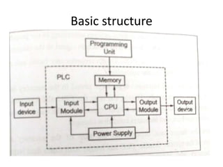
UNIT 4
PROGRAMMABLE LOGIC CONTROLLER
Content
• Introduction
• Basic structure
• Input and output processing
• Programming
• Mnemonics
• Timers, counters and internal relays
• Data handling
• Selection of PLC
PROGRAMMABLE LOGIC
CONTROLLER
• A Programmable Logic Controller(PLC) is a
digital computer used for automation of
typically industrial electromechanical
processes, such as control of machinery on
factory assembly lines, amusement rides or
light fixtures.
Applications
• Automated manufacturing process
equipment and machinery
• Packaging and filling equipment
• Chemical mixing
• Conveyor systems and distillation etc.,
Features and specification
• They are rugged and designed to withstand
vibration, temperature, humidity and noise
• The interfacing for inputs and outputs is inside
the controller.
• They are easily programmed and have an
easily understood programming language.
• Programming is primarily concerned with
logic and switching operation.
Hardwired motor circuit
Hardwired motor circuit with PLC
Basic structure
• PLC is designed as a replacement for the
hardwired relay and timer logic, where PLC
provides ease and flexibility of control based
on programming and executive logical
instruction.
• The internal functions such as timers, counter
and shift registers making sophisticated control
possible using even the smallest PLC.
• PLC capable of performing function such as
– counting,
– logistics,
– numerical application,
– comparing and processing of signals.
• A PLC is divided in to 4 parts. They are
– Input/output module (I/O)
– Central processing Unit (CPU)
– Memory
– Programming unit
i) Input/output module (I/O)
• It is used to transfer the data between
external devices and CPU
• It is incorporated into PLC in two ways
I. Fixed I/O – it is a small unit that comes in one
piece with processor i.e., the I/O terminals
cannot be changed in fixed I/O
II. Modular I/O – it is packed together i.e., there
are several compartment of I/O module are
plugged together.
Central processing Unit (CPU)
• It is consisting of a microprocessor which
interrupts the input signal and carries out the
control actions according to the program stored
in the memory, communicating the decision as an
action signal to the output.
• It scan the total information package stored in
the memory and input and output devices
continuously.
• During the scan the CPU executes instruction
based on input data, sends appropriate output
responses to the output devices, updates data
acquisition systems and indicate condition
changes
• Scan time for larger unit depends on the
size of the memory and configuration of
the system
• Power supply unit is needed to convert
the AC voltage to the low DC voltage
necessary for the processor and to supply
power to other circuit in the input and
output interface module.
Memory Unit
• The memory in PLC stores the digital control
logic, the process program and the necessary
instruction to operate the system.
• The memory used in PLC are
• Non-volatile memory
• Volatile memory
• According to purpose of usage
• RAM –volatile memory
• ROM- permanent storage (Non-volatile memory )
Programming unit
• It is used to enter the required program
into the memory of the processor
• There are normally 3 approaches followed by
the program
–Use of hand held programmer
–Terminal with video display unit
–PC with appropriate software
Architecture of PLC
• BUSES
–Data buses – It is used for communicating
data b/w elements
–Address buses-It is used to read the address
of locations for accessing stored data
–Control buses- It is used for internal control
action carried by the CPU
–System buses- It is used for communication
b/n Input/output ports and input/output units
• Memory
– RAM (User program and data storage & volatile)
– ROM (Permanent storage)
• PROM ( Written once in the chip once received from the
manufacturer)
• EPROM ( Program Erased by the use of ultra voilet
light source and it can be reprogrammed and stored
permenantly)
• Electrically EPROM ( Program erased by Electrical
pulses)
Optoisolator
• Electrical Isolation from the external world is
usually by means of optoisolator
• When a digital pulses passes through the LED, a
pulse of Infrared radiation is produced.
• This pulses is detected by the phototransistor and
gives rise to a voltage in that circuit.
Optoisolator
Input channel with optoisolator
• Common input voltage is 5V and 24V
• Output voltage is 24V and 240V
• Output are often specified as being of
– Relay type
– Transistor type
– Triac type
Relay type of output
•The relay type output is used for both ac and dc
switching
•Relay are slow to operate
Transistor type output
•The transistor type output is used for dc switching
•This give faster switching action
Triac type of output
•The triac type output is used for switching AC voltages
•It act as a TWO WAY SILICON CONTROLLED
RECTIFIER
INPUT OUTPUT PROCESSING
• Processing of Input and output through PLC
programming
• Basic programming is LADDER PROGRAMMING
• PROGRAMMING SEQUENCE:
– Scan inputs with one rung of the ladder program
– Solve logic operations
– Set or reset the output of the rung
– Move on the next rung repeat operations, Step 1, Step2,
step 3.
TWO METHODS OF INPUT
OUTPUT PROCESSING
• CONTINEOUS UPDATING.
• MASS INPUT/OUTPUT COPYING.
PROGRAMMING
• The programming of PLC is based on the ladder
diagram.
• Ladder diagram involve writing a program in a
similar manner to drawing a switching circuit.
• Each rung must start with an input, or serious
of input and end with an output.
Switch controlling Solenoid
e.g., solenoid valve
open to allow water
to enter a vessel
Ladder Diagram for
Switch Control
Temperature Control System
Logic functions
An AND System
An OR System
Works with Two inputs and single output
A and B both are closed gives AND logic operations
Many inputs provides one output.
NOT System
NOR System
One input and one output.
OR function is inverted by NOT function
NAND System
XOR System
NAND function is inverted by NOT function
OR functions , with no input there is no output,
Sequencing
Cylinder Sequencing
A+, B+, A- and B-
Latching
• Ladder Latch circuit hold an output energised.
• Latch circuit used for the circuit carry out the
operation
• Coil maintain its status until different
condition occur
MNEMONICS
• A programmer can enter the program in to
PLC using Keyboard
• With the graphic symbols and ladder
elements
• Computer translates symbol in to machine
language
• Entering program that translates a ladder
program in to mnemonics
List of Mnemonics used for the
Mitsubishi f Series PLC
Mnemonics for Logic system
Timers, Internal relay and counters
• Task required for Series and Parallel
connections of input contacts.
• Tasks can involve Time delays and event counting
• EXAMPLE:
– For MITSUBISHI F Series, numbers are:
– Timers Delays on 0.1-999s
– Internal relays – 8 points
– Counters – 1 to 999
– POINT means there are timer circuit in system
– DELAY-ON Timer waits for a delay period.
TIMERS
• Timer circuit is specified by starting the
interval
• Timed events to be Start/ Stop
• Normally coils are energized result open or
closing the circuit
Timer
Timer circuit programmed to cause an output to
go ON for 0.5s, then OFF for 0.5s, then OFF for
0.5s and so on
ON-OFF
cycle timer
INTERNAL RELAYS (MARKER)
• RELAYS are able to Switch ON or OFF for
internal purpose
• It is used for multiple input connections
• Implementing switching connections
• It is used for starting the multiple outputs
Internal relay
COUNTER
• Counter are used to count a specific number of
contact operations
• EXAMPLE :
– Conveyor in the boxes
– Fruits filling
Counter
Master control relay
•Due to some internal relays, Simultaneously ON or
OFF the system totally shut down
•The alternate way to achieving without affecting the
RUNGS by using master ralays
JUMP Instruction
•Program A
encountered with
INPUT 1
CONDITIONAL
RELAY JUMP
(CJP)
•It occurs the
program jumps at
END OF JUMP (EJP)
Data handling
• Data movement
• Data comparison
• Arithmetic operation
• Code conversion
Data Movement
DATA COMPARISON
ARITHMETIC OPERATIONS
CODE CONVERSION
ANALOG INPUT/OUTPUT
Controlling the speed of motor:
Selection of PLC
• System definition
• Choosing the I/O hardware
• I/O timing consideration
• Analog I/O module –resolution, voltage level
• Conversion speed
• Analog closed control
• Communication
• Counter, encoders and positioning
• Selecting suppliers
• Choosing a correct processor

MECHATRONICS-UNIT 4-PROGRAMMABLE LOGIC CONTROLLER .ppt

  • 1.
  • 2.
    Content • Introduction • Basicstructure • Input and output processing • Programming • Mnemonics • Timers, counters and internal relays • Data handling • Selection of PLC
  • 3.
    PROGRAMMABLE LOGIC CONTROLLER • AProgrammable Logic Controller(PLC) is a digital computer used for automation of typically industrial electromechanical processes, such as control of machinery on factory assembly lines, amusement rides or light fixtures.
  • 4.
    Applications • Automated manufacturingprocess equipment and machinery • Packaging and filling equipment • Chemical mixing • Conveyor systems and distillation etc.,
  • 5.
    Features and specification •They are rugged and designed to withstand vibration, temperature, humidity and noise • The interfacing for inputs and outputs is inside the controller. • They are easily programmed and have an easily understood programming language. • Programming is primarily concerned with logic and switching operation.
  • 6.
  • 7.
  • 8.
  • 9.
    • PLC isdesigned as a replacement for the hardwired relay and timer logic, where PLC provides ease and flexibility of control based on programming and executive logical instruction. • The internal functions such as timers, counter and shift registers making sophisticated control possible using even the smallest PLC.
  • 10.
    • PLC capableof performing function such as – counting, – logistics, – numerical application, – comparing and processing of signals. • A PLC is divided in to 4 parts. They are – Input/output module (I/O) – Central processing Unit (CPU) – Memory – Programming unit
  • 11.
    i) Input/output module(I/O) • It is used to transfer the data between external devices and CPU • It is incorporated into PLC in two ways I. Fixed I/O – it is a small unit that comes in one piece with processor i.e., the I/O terminals cannot be changed in fixed I/O II. Modular I/O – it is packed together i.e., there are several compartment of I/O module are plugged together.
  • 12.
    Central processing Unit(CPU) • It is consisting of a microprocessor which interrupts the input signal and carries out the control actions according to the program stored in the memory, communicating the decision as an action signal to the output. • It scan the total information package stored in the memory and input and output devices continuously. • During the scan the CPU executes instruction based on input data, sends appropriate output responses to the output devices, updates data acquisition systems and indicate condition changes
  • 13.
    • Scan timefor larger unit depends on the size of the memory and configuration of the system • Power supply unit is needed to convert the AC voltage to the low DC voltage necessary for the processor and to supply power to other circuit in the input and output interface module.
  • 14.
    Memory Unit • Thememory in PLC stores the digital control logic, the process program and the necessary instruction to operate the system. • The memory used in PLC are • Non-volatile memory • Volatile memory • According to purpose of usage • RAM –volatile memory • ROM- permanent storage (Non-volatile memory )
  • 15.
    Programming unit • Itis used to enter the required program into the memory of the processor • There are normally 3 approaches followed by the program –Use of hand held programmer –Terminal with video display unit –PC with appropriate software
  • 16.
  • 17.
    • BUSES –Data buses– It is used for communicating data b/w elements –Address buses-It is used to read the address of locations for accessing stored data –Control buses- It is used for internal control action carried by the CPU –System buses- It is used for communication b/n Input/output ports and input/output units
  • 18.
    • Memory – RAM(User program and data storage & volatile) – ROM (Permanent storage) • PROM ( Written once in the chip once received from the manufacturer) • EPROM ( Program Erased by the use of ultra voilet light source and it can be reprogrammed and stored permenantly) • Electrically EPROM ( Program erased by Electrical pulses)
  • 19.
    Optoisolator • Electrical Isolationfrom the external world is usually by means of optoisolator • When a digital pulses passes through the LED, a pulse of Infrared radiation is produced. • This pulses is detected by the phototransistor and gives rise to a voltage in that circuit.
  • 20.
  • 21.
    Input channel withoptoisolator
  • 22.
    • Common inputvoltage is 5V and 24V • Output voltage is 24V and 240V • Output are often specified as being of – Relay type – Transistor type – Triac type
  • 23.
    Relay type ofoutput •The relay type output is used for both ac and dc switching •Relay are slow to operate
  • 24.
    Transistor type output •Thetransistor type output is used for dc switching •This give faster switching action
  • 25.
    Triac type ofoutput •The triac type output is used for switching AC voltages •It act as a TWO WAY SILICON CONTROLLED RECTIFIER
  • 26.
    INPUT OUTPUT PROCESSING •Processing of Input and output through PLC programming • Basic programming is LADDER PROGRAMMING • PROGRAMMING SEQUENCE: – Scan inputs with one rung of the ladder program – Solve logic operations – Set or reset the output of the rung – Move on the next rung repeat operations, Step 1, Step2, step 3.
  • 27.
    TWO METHODS OFINPUT OUTPUT PROCESSING • CONTINEOUS UPDATING. • MASS INPUT/OUTPUT COPYING.
  • 28.
    PROGRAMMING • The programmingof PLC is based on the ladder diagram. • Ladder diagram involve writing a program in a similar manner to drawing a switching circuit. • Each rung must start with an input, or serious of input and end with an output.
  • 32.
    Switch controlling Solenoid e.g.,solenoid valve open to allow water to enter a vessel Ladder Diagram for Switch Control
  • 33.
  • 34.
    Logic functions An ANDSystem An OR System Works with Two inputs and single output A and B both are closed gives AND logic operations Many inputs provides one output.
  • 35.
    NOT System NOR System Oneinput and one output. OR function is inverted by NOT function
  • 36.
    NAND System XOR System NANDfunction is inverted by NOT function OR functions , with no input there is no output,
  • 37.
  • 38.
    Latching • Ladder Latchcircuit hold an output energised. • Latch circuit used for the circuit carry out the operation • Coil maintain its status until different condition occur
  • 40.
    MNEMONICS • A programmercan enter the program in to PLC using Keyboard • With the graphic symbols and ladder elements • Computer translates symbol in to machine language • Entering program that translates a ladder program in to mnemonics
  • 41.
    List of Mnemonicsused for the Mitsubishi f Series PLC
  • 42.
  • 43.
  • 44.
    Timers, Internal relayand counters • Task required for Series and Parallel connections of input contacts. • Tasks can involve Time delays and event counting • EXAMPLE: – For MITSUBISHI F Series, numbers are: – Timers Delays on 0.1-999s – Internal relays – 8 points – Counters – 1 to 999 – POINT means there are timer circuit in system – DELAY-ON Timer waits for a delay period.
  • 45.
    TIMERS • Timer circuitis specified by starting the interval • Timed events to be Start/ Stop • Normally coils are energized result open or closing the circuit
  • 46.
  • 47.
    Timer circuit programmedto cause an output to go ON for 0.5s, then OFF for 0.5s, then OFF for 0.5s and so on ON-OFF cycle timer
  • 48.
    INTERNAL RELAYS (MARKER) •RELAYS are able to Switch ON or OFF for internal purpose • It is used for multiple input connections • Implementing switching connections • It is used for starting the multiple outputs
  • 49.
  • 50.
    COUNTER • Counter areused to count a specific number of contact operations • EXAMPLE : – Conveyor in the boxes – Fruits filling
  • 51.
  • 52.
    Master control relay •Dueto some internal relays, Simultaneously ON or OFF the system totally shut down •The alternate way to achieving without affecting the RUNGS by using master ralays
  • 53.
    JUMP Instruction •Program A encounteredwith INPUT 1 CONDITIONAL RELAY JUMP (CJP) •It occurs the program jumps at END OF JUMP (EJP)
  • 54.
    Data handling • Datamovement • Data comparison • Arithmetic operation • Code conversion
  • 55.
  • 56.
  • 57.
  • 58.
  • 59.
  • 60.
    Selection of PLC •System definition • Choosing the I/O hardware • I/O timing consideration • Analog I/O module –resolution, voltage level • Conversion speed • Analog closed control • Communication • Counter, encoders and positioning • Selecting suppliers • Choosing a correct processor