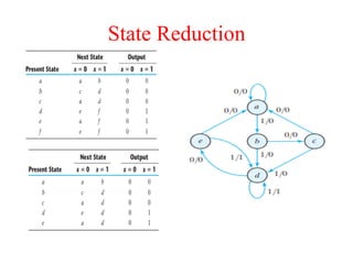
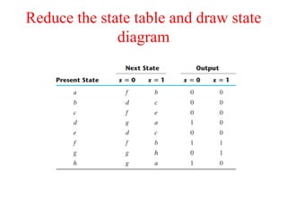
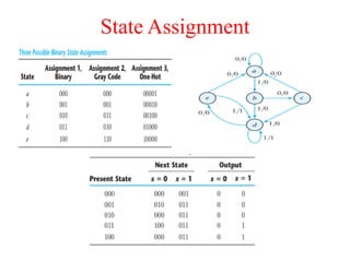
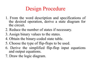
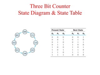
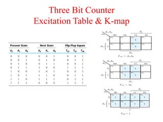
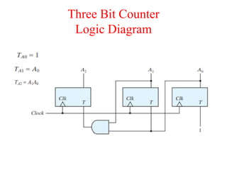
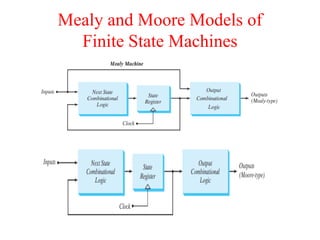
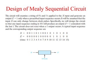
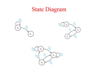
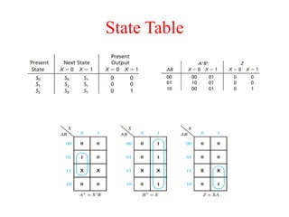
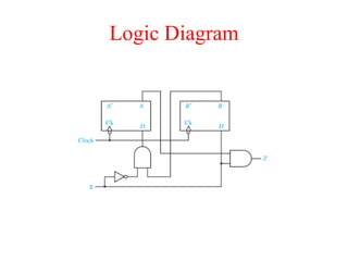
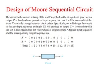
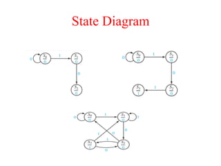
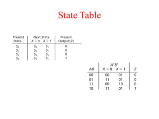
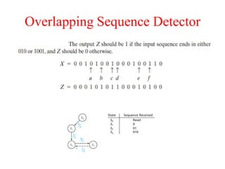
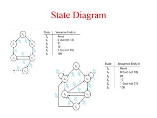
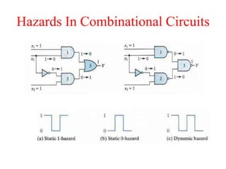
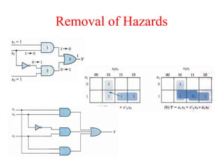
EC1371 – DIGITAL ELECTRONICS
Dr. K. Kannan, M.E., M.E., Ph.D.,
Professor & Head,
Department of Mechatronics Engineering
OBJECTIVES
• To provide the Digital fundamentals, Boolean algebra
and its applications in digital systems
• To familiarize with the design of various
combinational digital circuits using logic gates
• To introduce the analysis and design procedures for
synchronous and asynchronous sequential circuits
• To explain the various semiconductor memories and
related technology
• To introduce the electronic circuits involved in the
making of logic gates
UNIT 4
SYNCHRONOUS CIRCUIT DESIGN
• Design of Synchronous Sequential Circuits - State
Table and State Diagram - Design of Mealy and
Moore FSM
• Overlapping & Non-overlapping Sequence
detector
• Hazards - Hazard free realization - Case study on
Vending Machine FSM.
CO4 : Construct the synchronous sequential
circuits with hazard and hazard free conditions.
Analysis of
Synchronous Sequential Circuits
Analysis describes what a given circuit will do
under certain operating conditions.
The behavior of a clocked sequential circuit is
determined from the inputs, the outputs, and the
state of its flip-flops. The outputs and the next
state are both a function of the inputs and the
present state.
The analysis of a sequential circuit consists of
obtaining a table or a diagram for the time
sequence of inputs, outputs, and internal states.
Logic Diagram
State Equations
The behavior of a clocked
sequential circuit can be
described algebraically
by means of state
equations. A state
equation also called a
transition equation
specifies the next state as
a function of the present
state and inputs.
State Table
• The time sequence of inputs, outputs, and flip-
flop states can be enumerated in a state table
(sometimes called a transition table).
• The table consists of four sections labeled present
state, input, next state, and output . The present-
state section shows the states of flip-flops A and B
at any given time t . The input section gives a
value of x for each possible present state. The
next-state section shows the states of the flip-flops
one clock cycle later, at time t + 1. The output
section gives the value of y at time t for each
present state and input condition.
State Table
State Diagram
The information available in a state table can be
represented graphically in the form of a state
diagram. In this type of diagram, a state is
represented by a circle, and the (clock-
triggered) transitions between states are
indicated by directed lines connecting the
circles. The state diagram provides the same
information as the state table and is obtained
directly from state table
State Diagram
State Reduction
The reduction in the number of flip-flops in a
sequential circuit is referred to as the state-
reduction problem. State-reduction algorithms are
concerned with procedures for reducing the
number of states in a state table, while keeping
the external input–output requirements
unchanged.
Since m flip-flops produce 2m states, a reduction in
the number of states may or may not result in a
reduction in the number of flip-flops.
State Reduction
State Reduction
Reduce the state table and draw state
diagram
State Assignment
Design Procedure
1. From the word description and specifications of
the desired operation, derive a state diagram for
the circuit.
2. Reduce the number of states if necessary.
3. Assign binary values to the states.
4. Obtain the binary-coded state table.
5. Choose the type of flip-flops to be used.
6. Derive the simplified flip-flop input equations
and output equations.
7. Draw the logic diagram.
Three Bit Counter
State Diagram & State Table
Three Bit Counter
Excitation Table & K-map
Three Bit Counter
Logic Diagram
Mealy and Moore Models of
Finite State Machines
Sequence Detector
Design a circuit that detects a sequence of three
or more consecutive 1’s in a string of bits
coming through an input line.
Sequence Detector
Sequence Detector
Sequence Detector
Design of Mealy Sequential Circuit
State Diagram
State Table
Logic Diagram
Design of Moore Sequential Circuit
State Diagram
State Table
Overlapping Sequence Detector
State Diagram
HAZARDS
Hazards are unwanted switching transients that may
appear at the output of a circuit because different
paths exhibit different propagation delays.
Hazards occur in combinational circuits, where they
may cause a temporary false output value. When
they occur in asynchronous sequential circuits,
hazards may result in a transition to a wrong
stable state. It is there fore necessary to check for
possible hazards and determine whether they can
cause improper operations. If so, then steps must
be taken to eliminate their effect.
Hazards In Combinational Circuits
Removal of Hazards
Hazards in Sequential Circuits
Removal of Hazards
Essential Hazards
This type of hazard is caused by unequal delays along two
or more paths that originate from the same input.
An excessive delay through an inverter circuit in
comparison to the delay associated with the feedback
path may cause such a hazard.
Essential hazards cannot be corrected by adding
redundant gates as in static hazards. They can be
corrected by adjusting the amount of delay in the
affected path. To avoid essential hazards, each feedback
loop must be handled with individual care to ensure
that the delay in the feedback path is long enough
compared with delays of other signals that originate
from the input terminals.
Thank You

Digital Electronics – Unit IV.pdf

  • 1.
    EC1371 – DIGITALELECTRONICS Dr. K. Kannan, M.E., M.E., Ph.D., Professor & Head, Department of Mechatronics Engineering
  • 2.
    OBJECTIVES • To providethe Digital fundamentals, Boolean algebra and its applications in digital systems • To familiarize with the design of various combinational digital circuits using logic gates • To introduce the analysis and design procedures for synchronous and asynchronous sequential circuits • To explain the various semiconductor memories and related technology • To introduce the electronic circuits involved in the making of logic gates
  • 3.
    UNIT 4 SYNCHRONOUS CIRCUITDESIGN • Design of Synchronous Sequential Circuits - State Table and State Diagram - Design of Mealy and Moore FSM • Overlapping & Non-overlapping Sequence detector • Hazards - Hazard free realization - Case study on Vending Machine FSM. CO4 : Construct the synchronous sequential circuits with hazard and hazard free conditions.
  • 4.
    Analysis of Synchronous SequentialCircuits Analysis describes what a given circuit will do under certain operating conditions. The behavior of a clocked sequential circuit is determined from the inputs, the outputs, and the state of its flip-flops. The outputs and the next state are both a function of the inputs and the present state. The analysis of a sequential circuit consists of obtaining a table or a diagram for the time sequence of inputs, outputs, and internal states.
  • 5.
  • 6.
    State Equations The behaviorof a clocked sequential circuit can be described algebraically by means of state equations. A state equation also called a transition equation specifies the next state as a function of the present state and inputs.
  • 7.
    State Table • Thetime sequence of inputs, outputs, and flip- flop states can be enumerated in a state table (sometimes called a transition table). • The table consists of four sections labeled present state, input, next state, and output . The present- state section shows the states of flip-flops A and B at any given time t . The input section gives a value of x for each possible present state. The next-state section shows the states of the flip-flops one clock cycle later, at time t + 1. The output section gives the value of y at time t for each present state and input condition.
  • 8.
  • 9.
    State Diagram The informationavailable in a state table can be represented graphically in the form of a state diagram. In this type of diagram, a state is represented by a circle, and the (clock- triggered) transitions between states are indicated by directed lines connecting the circles. The state diagram provides the same information as the state table and is obtained directly from state table
  • 10.
  • 11.
    State Reduction The reductionin the number of flip-flops in a sequential circuit is referred to as the state- reduction problem. State-reduction algorithms are concerned with procedures for reducing the number of states in a state table, while keeping the external input–output requirements unchanged. Since m flip-flops produce 2m states, a reduction in the number of states may or may not result in a reduction in the number of flip-flops.
  • 12.
  • 13.
  • 14.
    Reduce the statetable and draw state diagram
  • 15.
  • 16.
    Design Procedure 1. Fromthe word description and specifications of the desired operation, derive a state diagram for the circuit. 2. Reduce the number of states if necessary. 3. Assign binary values to the states. 4. Obtain the binary-coded state table. 5. Choose the type of flip-flops to be used. 6. Derive the simplified flip-flop input equations and output equations. 7. Draw the logic diagram.
  • 17.
    Three Bit Counter StateDiagram & State Table
  • 18.
  • 19.
  • 20.
    Mealy and MooreModels of Finite State Machines
  • 21.
    Sequence Detector Design acircuit that detects a sequence of three or more consecutive 1’s in a string of bits coming through an input line.
  • 22.
  • 23.
  • 24.
  • 25.
    Design of MealySequential Circuit
  • 26.
  • 27.
  • 28.
  • 29.
    Design of MooreSequential Circuit
  • 30.
  • 31.
  • 32.
  • 33.
  • 34.
    HAZARDS Hazards are unwantedswitching transients that may appear at the output of a circuit because different paths exhibit different propagation delays. Hazards occur in combinational circuits, where they may cause a temporary false output value. When they occur in asynchronous sequential circuits, hazards may result in a transition to a wrong stable state. It is there fore necessary to check for possible hazards and determine whether they can cause improper operations. If so, then steps must be taken to eliminate their effect.
  • 35.
  • 36.
  • 37.
  • 38.
  • 39.
    Essential Hazards This typeof hazard is caused by unequal delays along two or more paths that originate from the same input. An excessive delay through an inverter circuit in comparison to the delay associated with the feedback path may cause such a hazard. Essential hazards cannot be corrected by adding redundant gates as in static hazards. They can be corrected by adjusting the amount of delay in the affected path. To avoid essential hazards, each feedback loop must be handled with individual care to ensure that the delay in the feedback path is long enough compared with delays of other signals that originate from the input terminals.
  • 40.