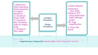
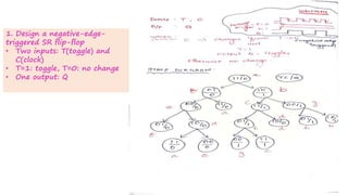
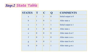
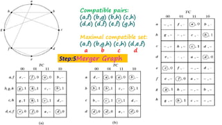
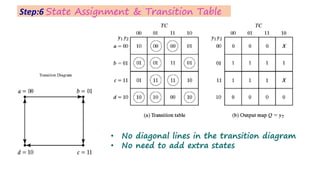
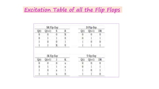
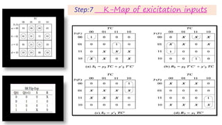
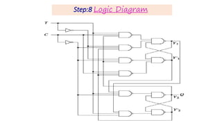
This document discusses the design procedure for an asynchronous sequential circuit in pulse mode. It involves 6 steps: 1) Deriving the state table from the state diagram, 2) Constructing the primitive flow table, 3) Reducing the flow table by merging compatible states, 4) Assigning binary states without races, 5) Obtaining the transition table and output map, 6) Drawing the logic diagram using SR latches. An example of designing a negative edge triggered SR flip-flop is provided to illustrate the procedure.