This document provides information about Numerical Control (NC) and Computer Numerical Control (CNC) machines. It discusses:
- The difference between NC and CNC machines, with CNC machines having more advanced computer control capabilities than early NC machines controlled by tape or cards.
- The history and evolution of CNC, starting from early NC machines developed in the 1940s-1950s controlled by punch cards and tape, to the introduction of microprocessors and computers enabling more advanced CNC machines from the 1970s onward.
- Key enhancements provided by CNC over NC include canned cycles, sub-programming, compensation functions, and more complex interpolation capabilities like B-splines.
- CNC
Cnc tooling for cnc machine(130670119596)Kushal Shah
we have seen what the NC machine is and its various
parts, it is easier to understand what the CNC machine is. CNC is
the short form for Computer Numerical control. We have seen that
the NC machine works as per the program of instructions fed into
the controller unit of the machine. The CNC machine comprises of
the mini computer or the microcomputer that acts as the controller
unit of the machine. While in the NC machine the program is fed
into the punch cards, in CNC machines the program of instructions
is fed directly into the computer via a small board similar to the
traditional keyboard.
Advantages & Limitations of CNC machine tools,Introduction DNC,Component of a DNC system,Principle,Functions of DNC
Types of DNC systems,Comparison between NC, CNC and DNC machine tools
APT stands for Automatically Programmed Tool. It is a language that defines the tool path with respect to the part
geometry, and often forms the basis for post-processor generated NC files.
Modern precision manufacturing demands extreme dimensional accuracy and surface finish.Such performance is very difficult to achieve manually, if not impossible, even with expert operators. In cases where it is possible, it takes much higher time due to the need for frequent dimensional measurement to prevent overcutting. It is thus obvious that automated motion control would replace manual “handwheel” control in modern manufacturing. Development of computer numerically controlled (CNC) machines has also made possible the automation of the machining processes with flexibility to handle production of small to medium batch of parts. In the 1940s when the U.S. Air Force perceived the need to manufacture complex parts for highspeed aircraft. This led to the development of computer-based automatic machine tool controls also known as the Numerical Control (NC) systems. Commercial production of NC machine tools started around the fifties and sixties around the world. Note that at this time the microprocessor has not yet been invented. Initially, the CNC technology was applied on lathes, milling machines, etc. which could perform a single type of metal cutting operation. Later, attempt was made to handle a variety of workpieces that may require several different types machining operations and to finish them in a single set-up. Thus CNC machining Centres capable of performing multiple operations were developed. To start with, CNC machining centres were developed for machining prismatic components combining operations like milling, drilling, boring and tapping. Gradually machines for manufacturing cylindrical components, called turning centers were developed.
Automatically controlling a machine tool based on a set of pre-programmed machining and movement instructions is known as numerical control, or NC.In a typical NC system the motion and machining instructions and the related numerical data, together called a part program, used to be written on a punched tape. The part program is arranged in the form of blocks of information, each related to a particular operation in a sequence
of operations needed for producing a mechanical component. The punched tape used to be read one block at a time. Each block contained, in a particular syntax, information needed for processing a particular machining instruction such as, the segment length, its cutting speed, feed, etc. These pieces of information were related to the final dimensions of the workpiece (length, width, and radii of circles) and the contour forms (linear, circular, or other) as per the drawing. Based on these dimensions, motion commands were given separately for each axis of motion. Other instructions and related machining parameters, such as cutting speed, feed rate, as well as auxiliary functions related to coolant flow, spindle speed, part clamping, are also provided in part programs depending on manufacturing specifications such as tolerance and surface finish. Punched tapes are mostly obsolete.
CNC Programming for Begainer.
1.Easy Mehtod.
2.Complete Theoritical Knowledge.
3.Motion and coordinate system for NC machine.
4.Axes convention of VMC & HMC.
5.How to make Part Programming.
6.Coordinates System.
7.Programming Format.
8.List of G Codes And M Codes.
9.How to Use of Above Codes In Programme.
10.Reference Point and Return of Machine.
CNC programming (Computer Numerical Control Programming) is utilized by manufacturers to create program instructions for computers to control a machine tool. CNC is highly involved in the manufacturing process and improves automation as well as flexibility.
Computer Numerical Control (CNC) Machining is the process through which computers control machine-based processes in manufacturing. The kinds of machines controlled include lathes, mills, routers and grinders – all used for manufacturing of metal and plastic products.
Numerical control (NC) is the automation of machine tools that are operated by precisely programmed commands encoded on a storage medium, as opposed to controlled manually.
Most NC today is computer numerical control (CNC), in which computers play an integral part of the control.
In modern CNC systems, end-to-end component design is highly automated using computer-aided design (CAD) and computer-aided manufacturing (CAM) programs
TECHNICAL TRAINING MANUAL GENERAL FAMILIARIZATION COURSEDuvanRamosGarzon1
AIRCRAFT GENERAL
The Single Aisle is the most advanced family aircraft in service today, with fly-by-wire flight controls.
The A318, A319, A320 and A321 are twin-engine subsonic medium range aircraft.
The family offers a choice of engines
Automobile Management System Project Report.pdfKamal Acharya
The proposed project is developed to manage the automobile in the automobile dealer company. The main module in this project is login, automobile management, customer management, sales, complaints and reports. The first module is the login. The automobile showroom owner should login to the project for usage. The username and password are verified and if it is correct, next form opens. If the username and password are not correct, it shows the error message.
When a customer search for a automobile, if the automobile is available, they will be taken to a page that shows the details of the automobile including automobile name, automobile ID, quantity, price etc. “Automobile Management System” is useful for maintaining automobiles, customers effectively and hence helps for establishing good relation between customer and automobile organization. It contains various customized modules for effectively maintaining automobiles and stock information accurately and safely.
When the automobile is sold to the customer, stock will be reduced automatically. When a new purchase is made, stock will be increased automatically. While selecting automobiles for sale, the proposed software will automatically check for total number of available stock of that particular item, if the total stock of that particular item is less than 5, software will notify the user to purchase the particular item.
Also when the user tries to sale items which are not in stock, the system will prompt the user that the stock is not enough. Customers of this system can search for a automobile; can purchase a automobile easily by selecting fast. On the other hand the stock of automobiles can be maintained perfectly by the automobile shop manager overcoming the drawbacks of existing system.
Saudi Arabia stands as a titan in the global energy landscape, renowned for its abundant oil and gas resources. It's the largest exporter of petroleum and holds some of the world's most significant reserves. Let's delve into the top 10 oil and gas projects shaping Saudi Arabia's energy future in 2024.
Quality defects in TMT Bars, Possible causes and Potential Solutions.PrashantGoswami42
Maintaining high-quality standards in the production of TMT bars is crucial for ensuring structural integrity in construction. Addressing common defects through careful monitoring, standardized processes, and advanced technology can significantly improve the quality of TMT bars. Continuous training and adherence to quality control measures will also play a pivotal role in minimizing these defects.
Overview of the fundamental roles in Hydropower generation and the components involved in wider Electrical Engineering.
This paper presents the design and construction of hydroelectric dams from the hydrologist’s survey of the valley before construction, all aspects and involved disciplines, fluid dynamics, structural engineering, generation and mains frequency regulation to the very transmission of power through the network in the United Kingdom.
Author: Robbie Edward Sayers
Collaborators and co editors: Charlie Sims and Connor Healey.
(C) 2024 Robbie E. Sayers
Cosmetic shop management system project report.pdfKamal Acharya
Buying new cosmetic products is difficult. It can even be scary for those who have sensitive skin and are prone to skin trouble. The information needed to alleviate this problem is on the back of each product, but it's thought to interpret those ingredient lists unless you have a background in chemistry.
Instead of buying and hoping for the best, we can use data science to help us predict which products may be good fits for us. It includes various function programs to do the above mentioned tasks.
Data file handling has been effectively used in the program.
The automated cosmetic shop management system should deal with the automation of general workflow and administration process of the shop. The main processes of the system focus on customer's request where the system is able to search the most appropriate products and deliver it to the customers. It should help the employees to quickly identify the list of cosmetic product that have reached the minimum quantity and also keep a track of expired date for each cosmetic product. It should help the employees to find the rack number in which the product is placed.It is also Faster and more efficient way.
Courier management system project report.pdfKamal Acharya
It is now-a-days very important for the people to send or receive articles like imported furniture, electronic items, gifts, business goods and the like. People depend vastly on different transport systems which mostly use the manual way of receiving and delivering the articles. There is no way to track the articles till they are received and there is no way to let the customer know what happened in transit, once he booked some articles. In such a situation, we need a system which completely computerizes the cargo activities including time to time tracking of the articles sent. This need is fulfilled by Courier Management System software which is online software for the cargo management people that enables them to receive the goods from a source and send them to a required destination and track their status from time to time.
Forklift Classes Overview by Intella PartsIntella Parts
Discover the different forklift classes and their specific applications. Learn how to choose the right forklift for your needs to ensure safety, efficiency, and compliance in your operations.
For more technical information, visit our website https://intellaparts.com
CFD Simulation of By-pass Flow in a HRSG module by R&R Consult.pptxR&R Consult
CFD analysis is incredibly effective at solving mysteries and improving the performance of complex systems!
Here's a great example: At a large natural gas-fired power plant, where they use waste heat to generate steam and energy, they were puzzled that their boiler wasn't producing as much steam as expected.
R&R and Tetra Engineering Group Inc. were asked to solve the issue with reduced steam production.
An inspection had shown that a significant amount of hot flue gas was bypassing the boiler tubes, where the heat was supposed to be transferred.
R&R Consult conducted a CFD analysis, which revealed that 6.3% of the flue gas was bypassing the boiler tubes without transferring heat. The analysis also showed that the flue gas was instead being directed along the sides of the boiler and between the modules that were supposed to capture the heat. This was the cause of the reduced performance.
Based on our results, Tetra Engineering installed covering plates to reduce the bypass flow. This improved the boiler's performance and increased electricity production.
It is always satisfying when we can help solve complex challenges like this. Do your systems also need a check-up or optimization? Give us a call!
Work done in cooperation with James Malloy and David Moelling from Tetra Engineering.
More examples of our work https://www.r-r-consult.dk/en/cases-en/
Hybrid optimization of pumped hydro system and solar- Engr. Abdul-Azeez.pdffxintegritypublishin
Advancements in technology unveil a myriad of electrical and electronic breakthroughs geared towards efficiently harnessing limited resources to meet human energy demands. The optimization of hybrid solar PV panels and pumped hydro energy supply systems plays a pivotal role in utilizing natural resources effectively. This initiative not only benefits humanity but also fosters environmental sustainability. The study investigated the design optimization of these hybrid systems, focusing on understanding solar radiation patterns, identifying geographical influences on solar radiation, formulating a mathematical model for system optimization, and determining the optimal configuration of PV panels and pumped hydro storage. Through a comparative analysis approach and eight weeks of data collection, the study addressed key research questions related to solar radiation patterns and optimal system design. The findings highlighted regions with heightened solar radiation levels, showcasing substantial potential for power generation and emphasizing the system's efficiency. Optimizing system design significantly boosted power generation, promoted renewable energy utilization, and enhanced energy storage capacity. The study underscored the benefits of optimizing hybrid solar PV panels and pumped hydro energy supply systems for sustainable energy usage. Optimizing the design of solar PV panels and pumped hydro energy supply systems as examined across diverse climatic conditions in a developing country, not only enhances power generation but also improves the integration of renewable energy sources and boosts energy storage capacities, particularly beneficial for less economically prosperous regions. Additionally, the study provides valuable insights for advancing energy research in economically viable areas. Recommendations included conducting site-specific assessments, utilizing advanced modeling tools, implementing regular maintenance protocols, and enhancing communication among system components.
Industrial Training at Shahjalal Fertilizer Company Limited (SFCL)MdTanvirMahtab2
This presentation is about the working procedure of Shahjalal Fertilizer Company Limited (SFCL). A Govt. owned Company of Bangladesh Chemical Industries Corporation under Ministry of Industries.
About
Indigenized remote control interface card suitable for MAFI system CCR equipment. Compatible for IDM8000 CCR. Backplane mounted serial and TCP/Ethernet communication module for CCR remote access. IDM 8000 CCR remote control on serial and TCP protocol.
• Remote control: Parallel or serial interface.
• Compatible with MAFI CCR system.
• Compatible with IDM8000 CCR.
• Compatible with Backplane mount serial communication.
• Compatible with commercial and Defence aviation CCR system.
• Remote control system for accessing CCR and allied system over serial or TCP.
• Indigenized local Support/presence in India.
• Easy in configuration using DIP switches.
Technical Specifications
Indigenized remote control interface card suitable for MAFI system CCR equipment. Compatible for IDM8000 CCR. Backplane mounted serial and TCP/Ethernet communication module for CCR remote access. IDM 8000 CCR remote control on serial and TCP protocol.
Key Features
Indigenized remote control interface card suitable for MAFI system CCR equipment. Compatible for IDM8000 CCR. Backplane mounted serial and TCP/Ethernet communication module for CCR remote access. IDM 8000 CCR remote control on serial and TCP protocol.
• Remote control: Parallel or serial interface
• Compatible with MAFI CCR system
• Copatiable with IDM8000 CCR
• Compatible with Backplane mount serial communication.
• Compatible with commercial and Defence aviation CCR system.
• Remote control system for accessing CCR and allied system over serial or TCP.
• Indigenized local Support/presence in India.
Application
• Remote control: Parallel or serial interface.
• Compatible with MAFI CCR system.
• Compatible with IDM8000 CCR.
• Compatible with Backplane mount serial communication.
• Compatible with commercial and Defence aviation CCR system.
• Remote control system for accessing CCR and allied system over serial or TCP.
• Indigenized local Support/presence in India.
• Easy in configuration using DIP switches.
2. What is NC/CNC?
NC is an acronym for Numerical Control and CNC is an
acronym for Computer Numerical Control.
3.
4. What is the difference between NC and CNC ?
The difference between NC and CNC is one of age and
capability.
The earliest NC machines performed limited functions
and movements controlled by punched tape or punch
cards.
As the technology evolved, the machines were equiped
with increasingly powerful microprocessors (computers)
with the addition of these computers, NC machines
become CNC machines.
CNC machines have far more capability than their
predecessor. contd…..
5. What is the difference between NC and CNC ?
Some of the enhancements that came along with CNC
include: Canned Cycles, Sub Programming,
Compensation, Work coordinates, Coordinate
Cutter
system
rotation, automatic corner rounding, chamfering, and B-
spline interpolation.
6. Where did CNC get started?
1940 Jhon Parson developed first machine able to drill
holes at specific coordinates programmed on punch
cards.
1951 MIT developedservo-mechanism
1952 MIT developed first NC machines formilling.
1970 First CNC machines came intopicture
Now-a-day’s modified 1970’s machines areused.
7. Are CNC machines more accurate
than conventional machines?
Yes, they can be. But like anything else it depends on
who is running the machine, how well the machines has
been maintained, qualityof setupand so on.
8. NC/CNC Machines-Advantages
High Repeatability and Precision e.g. Aircraftparts
Volume of production is veryhigh
Complex contours/surfaces need to be machined. E.g.
Turbines
Flexibility in job change, automatic tool settings, less
scrap
More safe, higher productivity, betterquality
Less paper work, faster prototype production, reduction
in lead times
10. IES - 1999
Consider the following statements regarding
numerically controlled machine tools:
1.They reduce non-productivetime
2. They reducefixturing
3.They reduce maintenance cost
Which of these statements arecorrect?
(a) 1, 2 and 3 (b) 1 and 2
(c) 2 and 3 (d) 1 and 3
11. NC/CNC/DNC
Direct Numerical Control is a system that uses a
central computertocontrol several machines at the same
time
Distributed Numerical Control (DNC): the central
computer downloads complete programs to the CNC
machines, which can be workstations or PCs, and can get
the information for the machineoperations.
The speed of the system is increased, large files can be
handled and the number of machine tools used is
expanded.
16
14. JWM 2010
Consider the following advantages of DNC systems:
1. Time-sharing
2. Greater computational capability
3. Remote computer location
Which of the above is/are correct?
(a) 1 and 2 only
(c) 2 only
(b) 2 and 3only
(d) 1, 2 and 3
15. IES – 2002 S-1
with List II and select the correctMatch List I
answer:
List I
(NC machine tool systems)
List II
(Features)
A. NC system 1.
B. CNC system 2.
It has an integrated automatic tool
changing unit and a component
indexing device
A number of machine tools are
controlled by a computer. No tape
reader, the part program is
transmitted directly to the
machine tool fromthe
computermemory
16. IES – 2002 Contd….. From S-1
C. DNC system 3. The controller consistsof
soft-wired computerand
Graphic
D. Machining centre 4.
hard- wired logic
display of tool pathis
alsopossible
The instructions on tape is
prepared in binary
decimal form and operated by
a series ofcoded
instructions
Codes:A B C D A B C D
(a) 4 2 3 1 (b) 1 3 2 4
(c) 4 3 2 1 (d) 1 2 3 4
17. Stepper Motor
The stepper motor is special type of synchronous motor
which is designed to rotate through a specific angle
(Called step) for each electrical pulse received from the
control unit.
20. Basic Length Unit (BLU)
In NC machine, the displacement length per one pulse
output from machine is defined as a Basic Length Unit
(BLU).
In the CNC computer each bit (binary digit) represents 1
BLU.
Bit = BLU
Example: If one pulse makes a servo motor rotate by one
degree and the servo motor moves the table by 0.0001
mm, one BLU will be 0.0001 mm.
The lead of a ball screw is related to the displacement
unit of the machine tooltable.
21.
22.
23. Example
A DC servomotor is coupled directly to a leadscrew
which drives the table of an NC machine tool. A
digital encoder, which emits 500 pulses per
revolution, is mounted on the other end of the
leadscrew. If the leadscrew pitch is 5 mm and the
motor rotates at 600 rpm,calculate
(a) The linear velocity of thetable
(b) The BLU of the NCsystem
(c) The frequency of pulses transmitted by theencoder.
24. IES 2011 Conventional
The table of a CNC machine is driven by a Lead screw which
is rotated by a DC servomotor. A digital encoder which emits
1000 pulses per second is mounted on the lead screw as a
feedback device. If the lead screw pitch is 6 mm and motor
rotates at 500 rpm,find
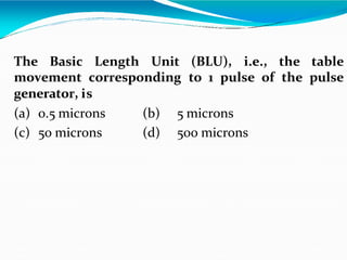
1. Basic length Units of thesystem
2. Linear velocity of thetable.
3. Frequency of pulses generated by the feedbackdevice.
[5 Marks]
25. Gate 2008 (PI)
In the feed drive of a Point-to-Point open loop CNC
drive, a stepper motor rotating at 200 steps/rev drives a
table through a gear box and lead screw-nut mechanism
(pitch = 4 mm, number of starts = 1).
is given by U=
The stepper motor (driven by voltage pulses from a pulse
generator) executes 1 step/pulse of the pulse generator.
The frequency of the pulse train from the pulse
generator is f = 10,000 pulses perminute.
Output rotational speed
The gear ratio =Input rotational speed
1
4
26. The Basic Length Unit (BLU), i.e., the table
movement corresponding to 1 pulse of the pulse
generator, is
(a) 0.5 microns (b) 5 microns
(c) 50 microns (d) 500 microns
28. GATE - 1992
of the tool is
In a point-to-point type of NCsystem
(a) Control of position and velocity
essential
(b) Control of only position of the tool is sufficient
(c) Control of only velocity of the tool is sufficient
(d) Neither position nor velocity need be controlled
32. GATE-2005
Which among the NC operations given below are
continuous pathoperations?
Arc Welding (AW)
Drilling (D)
Laser Cutting of Sheet Metal (LC)
Milling (M)
Punching is Sheet Metal (P)
Spot Welding (SW)
(a) AW,LC and M
(c) D, LC, P and SW
(b) AW,D, LC and M
(d) D, LC, and SW
33. Co-ordinate system
All the machine tool use Cartesian Co-ordinatesystem.
The first axis to be identified is the Z – axis, This is
followed by X and Y axesrespectively.
Right-hand coordinatesystems
34.
35.
36. IES - 2000
Assertion (A): The axis of an NC drilling machine
spindle is denoted asz-axis.
Reason (R): In NC machine tool, the axis
perpendicular to both x- and y-axis is designated as
z-axis
(a)Both A and R are individually true and R is the correct
explanation of A
(b)Both A and R are individually true but R is not the
correct explanation of A
(c) A is true but R isfalse
(d) A is false but R istrue
40. IES - 1996
Assertion (A): Numerically controlled machines
having more than three axes do notexist.
Reason (R): There are only three Cartesian
coordinates namelyx-y-z.
(a)Both A and R are individually true and R is the
correct explanation of A
(b)Both A and R are individually true but R is not the
correct explanation of A
(c) A is true but R isfalse
(d) A is false but R istrue
41. Absolute and Incremental Coordinate System
Absolute Coordinate System Incremental Coordinate System
42. GATE -2012 Same Q in GATE-2012 (PI)
A CNC vertical milling machine has to cut a
straight slot of 10 mm width and 2 mm depth by a
cutter of 10 mm diameter between points (0, 0)
and (100, 100) on the XY plane (dimensions in
mm). The feed rate used for milling is 50 mm/min.
Milling time for the slot (in seconds)is
(a) 120 (b) 170 (c) 180 (d) 240
43. The following are the steps to be followed
while developing the CNC part programs.
Process planning
Axesselection
Tool selection
Cutting process parametersplanning
Job and tool setupplanning
Machining path planning
Part program writing
Part programproving
44. For a CNC machine control unit (MCU) decides cutting
speed, feed, depth of cut, tool selection , coolant on off
and tool paths. The MCU issues commands in form of
numeric data to motors that position slides and tool
accordingly.
45. Part Programming
A part program is a set of instruction often referred to as
blocks each of which refers to a segment of the machining
performed by the machine tool
47. CNC programming
Important things to know:
• Coordinate System
• Units, incremental or absolute positioning
• Coordinates: X,Y,Z, RX,RY,RZ
• Feed rate and spindle speed
• Coolant Control: On/Off, Flood, Mist
• Tool Control: Tool and tool parameters
48. Programming Key Letters
O - Program number (Used forprogram identification)
N - Sequence number (Used for line identification)
G - Preparatory function
X - X axis designation
Y - Y axisdesignation
Z - Z axis designation
R - Radiusdesignation
F – Feed ratedesignation
S - Spindle speed designation
H - Tool length offsetdesignation
D - Tool radius offsetdesignation
T - ToolDesignation
M - Miscellaneousfunction
49. Table of Important G codes
Code Meaning Format
G00 Rapid Transverse N G00 X Y Z
G01 Linear Interpolation N G01 X Y Z F
G02 Circular Interpolation,
CW
N G02 X Y Z R F _
N G02 X Y Z I _J K F
G03 Circular Interpolation,
CCW
N G03 X Y _ Z R F
N G03 X Y Z I J K F
G04 Dwell N G04P
G17 XY Plane
G18 XZ Plane
G19 YZ Plane
50. Table of Important G codes
Code Meaning Format
G20/G70 Inch Unit
G21/G71 Metric Unit
G28 Automatic Return to Reference
Point
G40 Cutter compensation cancel
G41 Cutter compensation left N G41D
G42 Cutter compensation right N G42D
G43 Tool length compensation
(plus)
N G43H
51. Table of Important G codes
Code Meaning Format
G44 Tool length compensation
(minus)
N G44H
G49 Tool length compensation
cancel
G80 Cancel canned cycles
G81 Drilling cycle N G81 Z R F
G90 Absolute positioning
G91 Incremental positioning
G92 Absolute preset, changethe
datum position
N G92X Y Z
52. Rapid traverse: G00
G00:
to make the machine move at maximumspeed.
It is used for positioningmotion.
G90 G00 X20.0 Y10.0
Start
G90:
absolute
coordinates
(0,0)
(10,10)
End
(20,10)
53. Linear interpolation: G01
G01:
linear interpolation at feed
speed. G91 G0l X200.0
Y100.0F200.0
Y
100.0
XStart
End
200.0
G91:
incremental
coordinates
54. Circular interpolation: G02, G03
G02, G03:
Forcircular interpolation, the tool destinationand the circle
centerareprogrammed in one block
G02 is clockwise interpolation, G03 iscounter clock
wise interpolation
R
R
R
F ;
J K
Y Z
G03
G19
G02
F ;
I K
X Z
G03
G18
G02
F ;
I J
X Y
G03
G17
G02
End
point
Circle center, radius
55. Circular interpolation: G02, G03
G91 G02 X60.0 Y20.0 R50.0 F300.0
G91 G02 X60.0 Y20.0 R-50.0F300.0
Start
End
R=-50mm
Y
X
R=50mm
Specify Rwith
sign beforeit:
180° +R
>180° -R
56. Circular interpolation: G02, G03
Specify Center with I, J,K
I, J, K are the incremental
distance from the start of
thearc;
Viewing the startof arcas
the origin, I, J, K have
positive or negativesigns.
Center
Y
Start
End
X
i
j
57. Circular interpolation: G02, G03
N0010 G92 X200.0 Y40.0 Z0;
N0020 G90 G03 X140.0 Y100.0 R60.0 F300;
R60
R50
90 120 140 200
100
60
40
O
N0030 G02 X120.0 Y60.0 I90 J100 R50.0 F300
Y
X
G90:
absolute
coordinates
G92:
To define working
coordinate
58. GATE - 2004
During the execution of a CNC part programblock
N020 G02 X45.0 Y25.0 R5.0 the type of tool motion will
be
(a) Circular Interpolation – clockwise
(b) Circular Interpolation - counterclockwise
(c) Linear Interpolation
(d) Rapid feed
59. GATE - 2010
In a CNC program block, N002 G02 G91 X40 Z40…,
G02 and G91 referto
(a)Circular interpolation in counterclockwise direction
and incremental dimension
(b)Circular interpolation in counterclockwise direction
and absolutedimension
(c)Circular interpolation in clockwise direction and
incremental dimension
(d)Circular interpolation in clockwise direction and
absolute dimension
60. GATE - 2001
In an NC machining operation, the tool has to be
moved from point (5, 4) to point (7, 2) along a
circular path with centre at (5, 2). Before starting the
operation, the tool is at (5, 4). The correct G and M
code for this motionis
(a) N010 G03 X7.0 Y2.0 I5.0 J2.0
(b) N010 G02 X7.0 Y2.0 I5.0 J2.0
(c) N010 G01 X7.0 Y2.0 I5.0 J2.0
(d) N010 G00 X7.0 Y2.0 I5.0 J2.0
61. GATE - 2005
The tool of an NC machine has to move along a
circular arc from (5, 5) to (10,10) while performing an
operation. The centre of the arc is at (10, 5). Which
one of the following NC tool path commands
performs the above mentionedoperation?
(a) N010G02 X10 Y10 X5 Y5 R5
(b) N010G03 X10 Y10 X5 Y5 R5
(c) N010G01 X5 Y5 X10 Y10 R5
(d) N010G02 X5 Y5 X10 Y10 R5
62.
63. Tool Compensation
Tool-Radius Compensation
Left hand G41
Right hand G42
Cancel tool-radius compensation G40
Tool-Height Compensation
Positive G43
NegativeG44
Cancel tool-height compensation G49
64. Tool-Radius Compensation
Tool-radius compensations make it possible to
program directly from the drawing, and thus eliminate
the tool-offsetcalculation
G41 (G42) D
D: the radius of tool tocompensate is saved in a memory unit that
is named D
G41/G42 is directly related withdirectionof tool movementand
which side of part iscut.
65. Cancel Tool Compensation: G40
Note thedifference between twoways
N0060 G40 G01 X2.000 Y1.700M02
N0060 G01 X2.000Y1.700
N0070 G40 M02
ramp off block effectivetotheend point
66. GATE - 2000
In finish machining of an island on a casting with
CNC milling machine, an end mill with 10 mm
diameter is employed. The corner points of the
island are represented by (0, 0), (0, 30), (50, 30), and
(50, 0). By applying cutter radius right
compensation, the trajectory of the cutter willbe
(a) (-5, 0), (-5, 35), (55, 35), (55, -5), (-5, -5)
(b) (0, -5), (55, -5), (55, 35), (-5, 35), (-5, -5)
(c) (5, 5), (5, 25), (45, 25), (45, 5), (5, 5)
(d) (5, 5), (45, 5), (45, 25), (5, 25), (5, 5)
67. Tool-Height Compensation
G43 (G44) H
H: specified memory unit used tosave height
compensation of tool.
Positive compensation(G43):
real position = specified position + valuesaved in H
Negative compensation(G44):
real position = specified position - valuesaved in H
68.
69. Tool-Height Compensation
Example:
N0010 G91 G00 X12.0 Y80.0
N0020 G44 Z-32.0 H02;
If we put 0.5mm intoH02,
real position = -32.0 - 0.5 =-32.5
Cancel tool-height compensation:G49
G91:
incremental
coordinates
70. Table of Important M codes
M00 Programstop
M01 Optional programstop
M03 Spindle onclockwise
M04 Spindle oncounterclockwise
M05 Spindlestop
M06 Toolchange
M08 Coolanton
M09 Coolantoff
M10 Clamps on
M11 Clamps off
M02 or M30 Program stop, reset tostart
71. Rules for programming
Block Format
N135 G01 X1.0 Y1.0 Z0.125 F5
Sample Block
• Restrictions on CNC blocks
• Each may contain only one tool move
• Each may contain any number of non-tool move G-codes
• Each may contain only one feed rate
• Each may contain only one specified tool or spindle speed
• The block numbers should be sequential
• Both the program start flag and the program number must be
independent of all other commands (on separate lines)
• The data within a block should follow the sequence shown
in the above sample block
72.
73.
74. Example of CNC Programming
What Must Be Done To Drill A Hole On ACNC
Vertical Milling Machine
82. Top
View
Front
View
Tool At Home
O0001
N005 G54 G90 S600 M03
N005 SequenceNumber
G54 FixtureOffset
G90 Absolute Programming Mode
S600 Spindle Speed set to 600RPM
M03 Spindleon in a Clockwise Direction
83. Top
View
Front
View
O0001
N005 G54 G90 S600 M03
N010 G00 X1.0 Y1.0
G00
X1.0
Y1.0
Rapid Motion
X Coordinate 1.0 in. fromZero
Y Coordinate 1.0 in. fromZero
84. Top
View
Front
View
O0001
N005 G54 G90 S600 M03
N010 G00 X1.0 Y1.0
N015 G43 H01 Z.1 M08
G43
H01
Z.1
M08
Tool Length Compensation
Specifies Tool lengthcompensation
Z Coordinate .1 in. fromZero
Flood CoolantOn
85. Top
View
Front
View
O0001
N005 G54 G90 S600 M03
N010 G00 X1.0Y1.0
N015 G43 H01 Z.1 M08
N020 G01 Z-.75 F3.5
G01
Z-.75
F3.5
Straight Line Cutting Motion
Z Coordinate -.75 in. from Zero
Feed Rate set to 3.5in/min.
88. Top
View
Front
View
O0001
N005 G54 G90 S600 M03
N010 G00 X1.0Y1.0
N015 G43 H01 Z.1 M08
N020 G01 Z-.75 F3.5
N025 G00 Z.1 M09
N030 G91 G28 X0 Y0 Z0
N035 M30
M30 End of Program
89. IES - 1995
Match List I with List II and select the correct answer
using thecodesgiven below the lists:
List II
(Associated parameter)
ListI
(A functionconnected
with NC m/ctool)
A. Interpolation
B. Parity check
C. Preparatory function
D. Point to pointcontrol
Code:A B C D
1. Tapepreparation
2. Canned cycle
3. Drilling
4. Contouring
5. Turning
A B C D
(a) 4 1 2 3 (b) 4 1 2 5
(c) 5 1 3 2 (d) 1 4 3 2
90.
91. APT Language
APT (Automatically ProgrammedTools)
The APT language consists of many different types of
statements made up of the following valid letters, numerals
and punctuation marks.
Letters: ABCDEFGHIJKLMNOPQRSTUVWXYZ
Numerals: 0 1 2 3 4 5 6 7 8 9
/ A slash dividesa statement into twosections. eg.,
GO/PAST,
, A comma is used as a separator between theelements in
a statementgenerally to the right of the slash.
= An equals is used forassigning an entity toa symbolic
name, e.g., P1 = POINT/25,50,30.
92. Words
The words to be used in the statements are built up from
one to six letters or numerals with the first one being a
letter. No special character is allowed in thewords.
93. IES - 1998
Which of the following are the rules of
programming NC machine tools in APT language?
1.Only capital letters areused
2. A period is placed at theend of each statement
3.Insertion of space does not affect the APT word
Select thecorrect answerusing thecodes given below:
(a) 1 and 2 (b) 2 and 3
(c) 1 and 3 (d) 1 alone
94. The complete APT part program consists of
the following four types of statements
Geometry
Motion
Postprocessor
Compilation control
95. Other Part Programming Languages
ADAPT (ADaptation APT) was the first attempt to adapt APT
programming system for smallercomputers
AUTOSPOT (AUTOmatic Sytem for POsitioning Tools) was
developed by IBM and first introduced in1962
EXAPT (EXtended subset of APT) was developed jointly in
German in about 1964 by several universities to adapt APT for
European use. It is compatible with APT and thus can use the
same processor asAPT
COMPACT was developed by Manufacturing Data Systems, Inc.
(MDSI)
SPLIT (Sundstrand Processing Language Internally Translated)
was developed by Sundstrand Corporation, intended for its own
machinetools
MAPT (Micro-APT) is a subset of APT, to be run
microcomputers
on the
125