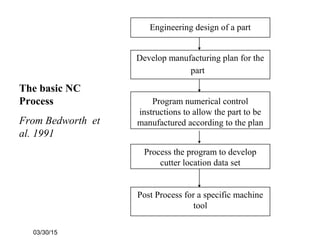
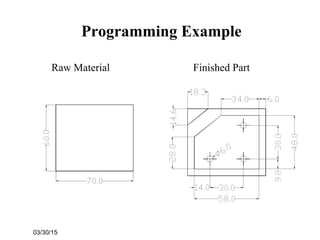
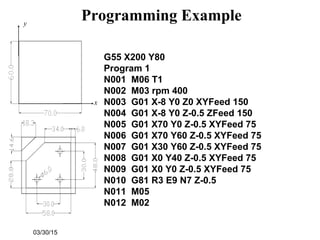
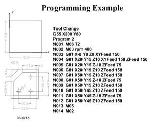
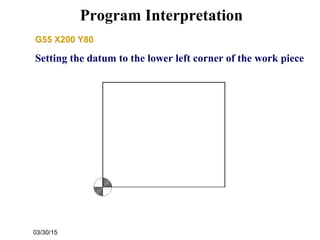
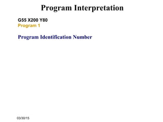
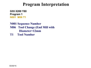
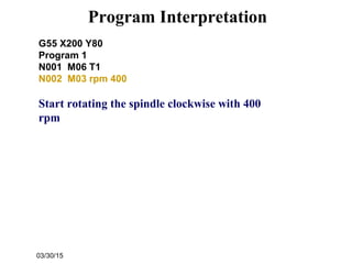
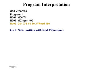
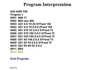
The document provides information about numerical control and computer numerical control (CNC) manufacturing. It discusses the components and process of numerical control, how CNC improved on this with a microprocessor, and part programming using APT. It then gives an example of an APT program for machining a cylindrical part and interpreting the code in the program.
![03/30/15
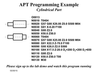
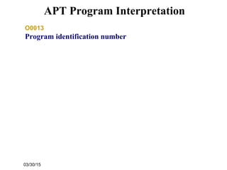
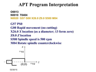
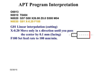
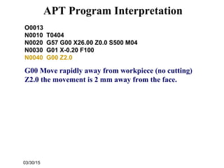
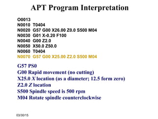
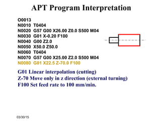
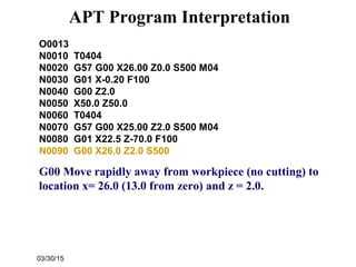
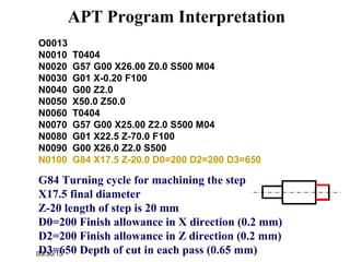
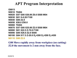
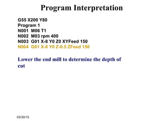
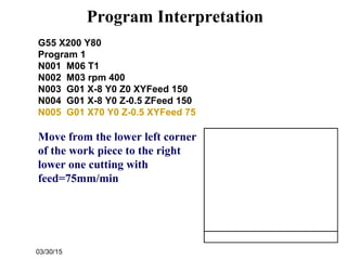
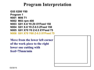
O0013
N0010 T0404
N0020 G57 G00 X26.00 Z0.0 S500 M04
N0030 G01 X-0.20 F100
N0040 G00 Z2.0
N0050 X50.0 Z50.0
Go to a safe location away from the
workpiece [x = 50 (25 from zero), z = 50] to
change the tool.
APT Program Interpretation](https://image.slidesharecdn.com/cnc-090429002318-phpapp02/85/CNC-19-320.jpg)


![Getting Started with Apache Spark: Big Data Made Simple [Free Meetup]](https://cdn.slidesharecdn.com/ss_thumbnails/apachesparkgettingstarted-260203175547-8361bcc3-thumbnail.jpg?width=640&height=640&fit=bounds)