Download to read offline


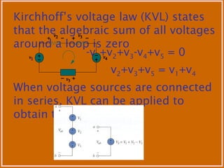


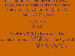


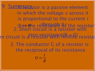


This document discusses basic circuit laws including Ohm's law, Kirchhoff's laws, and techniques for analyzing circuits. It defines key circuit elements and relationships. Ohm's law defines the relationship between voltage, current, and resistance. Kirchhoff's laws allow the use of nodes, loops, and branches to simplify circuit analysis. Resistors can be analyzed individually and in series and parallel combinations using these fundamental laws and techniques. Examples are provided to demonstrate applying the laws to calculate current, voltage, power, and equivalent resistances in various circuits.