Downloaded 284 times

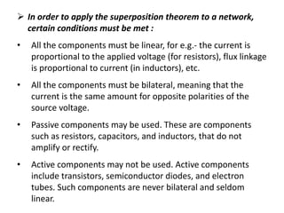

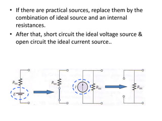
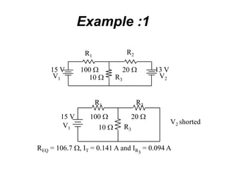
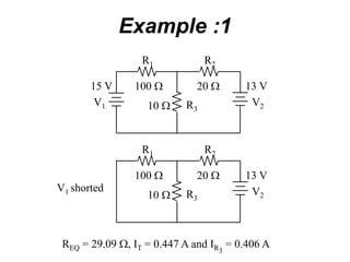
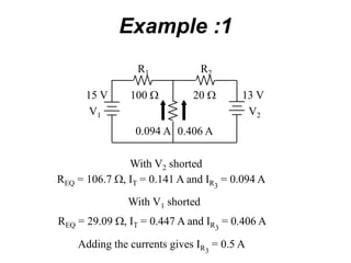
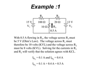
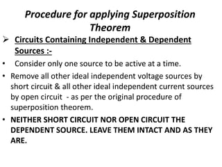
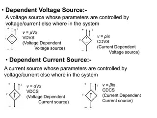
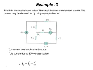
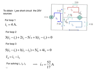
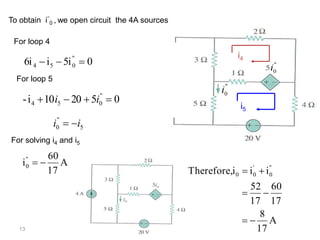


The superposition theorem allows analysts to determine the voltage across or current through an element in a linear, bilateral circuit containing multiple sources. It states that the response of such a circuit to multiple sources is equal to the sum of the responses to each source acting alone. To apply the theorem, each independent source is solved for separately while other sources are removed by shorting or opening. Dependent sources are left intact. The procedure is demonstrated through examples solving for currents using superposition in circuits with independent and dependent sources.