Module – I:
DC Circuits
and
Electromagn
etism
•D.C. Circuits:
o Introduction
o Series Circuits
o Parallel Circuits
o Series parallel
Combination circuits
o Kirchhoff's Current Law
o Kirchhoff's Voltage Law
o Illustrative problems
o Ohm’s law
•Power Generation:
o Renewable & Non-
Renewable energy
sources
o Hydro
o Nuclear
o Solar
o Wind power
generation
3.
Module 1a: D.C.
Circuits
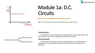
•D.C.: The current which does not vary with time is direct current
•Active Elements :
The elements of a circuit that possess energy of their own and can impact it on
other elements. Eg. Sources ( Voltage source & Current source)
•Passive Elements :
The elements which does not possess energy of their own and they receive
energy from sources are called passive elements. Eg. Resistors, Inductors and
Capacitors.
4.
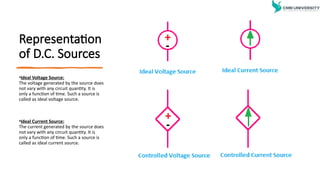
Representation
of D.C. Sources
•IdealVoltage Source:
The voltage generated by the source does
not vary with any circuit quantity. It is
only a function of time. Such a source is
called as ideal voltage source.
•Ideal Current Source:
The current generated by the source does
not vary with any circuit quantity. It is
only a function of time. Such a source is
called as ideal current source.
5.
Electric current: Therate at which the electric charge is transferred across a point in a conductor is known as
electric current. The unit of Electric Current is Ampere (A)
Electric Potential: At any point in a charged conductor is defined as the workdone to bring a unit positive
charge from infinity to that point. The unit is Volts(V).
Potential difference: Between any two points of the charged conductor is the amount of work that has to be
done to bring the unit positive charge from lower potential to higher potential. The unit is Volts(V).
Power: It is defined as the rate at which work is done. The unit is Watt(W)
Energy: The capacity to do the work. The unit is Joules/watt - Seconds
6.
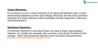
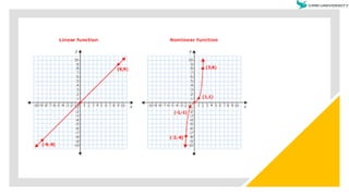
Linear Elements :
Inan electric circuit, a linear element is an electrical element with a linear
relationship between current and voltage. Resistors are the most common
example of a linear element other examples include capacitors, inductors,
and transformers.
Nonlinear Elements :
A nonlinear element is one which does not have a linear input/output
relation. In a diode, for example, the currents a non-linear function of the
voltage . Most semiconductor devices have non-linear characteristics.
8.
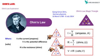
Georg Simon Ohm,
Germanphysicist,
16 March 1789 - 6 July 1854
Ohm’s Law Magic Triangle
Where: I is the current (amperes)
V is the potential difference
(volts)
R is the resistance (ohms)
V
I R
)
A
,
amperes
(
R
V
I
V
I R
)
,
ohms
(
I
V
R
)
V
,
volts
(
R
I
V
V
I R
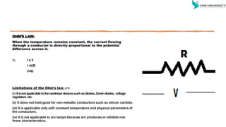
OHM’S LAW:
9.
OHM’S LAW:
When thetemperature remains constant, the current flowing
through a conductor is directly proportional to the potential
difference across it.
Ie, I α V
I =V/R
V=RI
Limitations of the Ohm’s law are,
(i) Itisnotapplicabletothenonlineardevicessuchasdiodes,Zenerdiodes, voltage
regulators etc.
(ii) It does not hold good for non-metallic conductors such as silicon carbide.
(iii) It is applicable only with constant temperature and physical parameters of
the conductors.
(iv) It is not applicable to arc lamps because arc produces or exhibits non
linear characteristics.
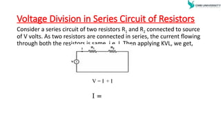
Voltage Division inSeries Circuit of Resistors
Consider a series circuit of two resistors R1 and R2 connected to source
of V volts. As two resistors are connected in series, the current flowing
through both the resistors is same, i.e. I. Then applying KVL, we get,
V = I + I
I =
12.
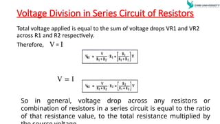
Voltage Division inSeries Circuit of Resistors
Total voltage applied is equal to the sum of voltage drops VR1 and VR2
across R1 and R2 respectively.
Therefore, V = I
V = I
So in general, voltage drop across any resistors or
combination of resistors in a series circuit is equal to the ratio
of that resistance value, to the total resistance multiplied by
13.
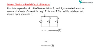
Current Division inParallel Circuit of Resistors
Consider a parallel circuit of two resistors R1 and R2 connected across a
source of V volts. Current through R1 is and R2 is , while total current
drawn from source is IT
= + ------------(1)
=
------------(2)
14.
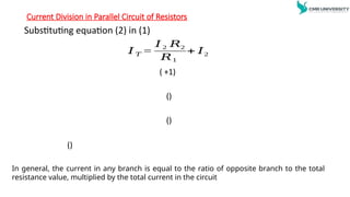
Current Division inParallel Circuit of Resistors
Substituting equation (2) in (1)
𝐼 𝑇 =
𝐼 2 𝑅2
𝑅1
+ 𝐼2
( +1)
()
()
()
In general, the current in any branch is equal to the ratio of opposite branch to the total
resistance value, multiplied by the total current in the circuit
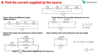
B. Find thecurrent supplied by the source
Step1: Name the different nodes Step3: Reduce the parallel elements into one
single element
Step2: Rearrange the elements as shown below Step 4: Reduce the series elements into one single
element
Step 5: Find the current supplied by the source as
+ -
2
2
2
2
1 0 V
+ -
2
2
2
2
10V
a b c d
e
+ -
2
2
2
2
1 0 V
a
b
c
d
e
+ -
2
67
.
0
1 0 V
a
b
c
d
e
+ -
67
.
2
1 0V
a e
2.67Ω
0.67
2
R
0.67Ω
R
2
1
2
1
2
1
R
1
3.75A
2.67
10
I
17.
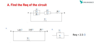
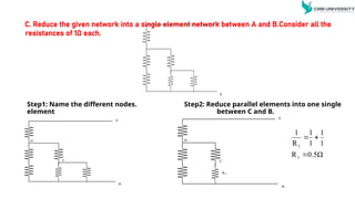
C. Reduce thegiven network into a single element network between A and B.Consider all the
resistances of 1Ω each.
Step1: Name the different nodes. Step2: Reduce parallel elements into one single
element between C and B.
A
B
A
B
C
D
A
B
C
D
R 1
0.5Ω
R
1
1
1
1
R
1
1
1
18.
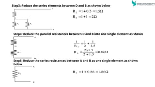
Step3: Reduce theseries elements between D and B as shown below
A
B
D
R 2
R 3
2
3
R 1 0.5 1.5Ω
R 1 1 2Ω
Step4: Reduce the parallel resistances between D and B into one single element as shown
A
B
D
R 4
Step5: Reduce the series resistances between A and B as one single element as shown
below
A
B
R 5
1.86Ω
0.86
1
R 5
0.86Ω
1.5
2
2x1.5
R
1.5
1
2
1
R
1
4
4
19.
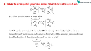
D . Reducethe series parallel network into a single network between the nodes X and Y
X
2
6
3
6
1
2
3
2
2
Y
Step1: Name the different nodes as shown below
X
2
6
3
6
1
2
3
2
2
Y
M
N
Step2: Reduce the series elements between X and M into one single element and also reduce the series
elements between N and Y into one single element as shown below (All the resistances are in series between
X and M and similarly all the resistances between N and Y are in series)
X
Y
6
6
6
6
M
N
3
20.
D . Reducethe series parallel network into a single network between
the nodes X and Y
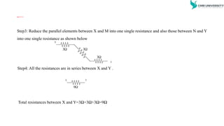
Step3: Reduce the parallel elements between X and M into one single resistance and also those between N and Y
into one single resistance as shown below
X
3
3
3
Y
Step4: All the resistances are in series between X and Y .
X
9
Y
Total resistances between X and Y=3Ω+3Ω+3Ω=9Ω
21.
Kirchhoff’s Law
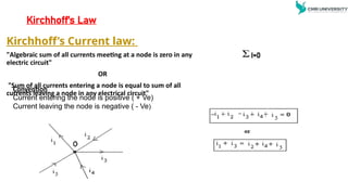
Kirchhoff’s Currentlaw:
"Algebraic sum of all currents meeting at a node is zero in any
electric circuit"
OR
"Sum of all currents entering a node is equal to sum of all
currents leaving a node in any electrical circuit"
I=0
Convention
Current entering the node is positive ( + Ve)
Current leaving the node is negative ( - Ve)
22.
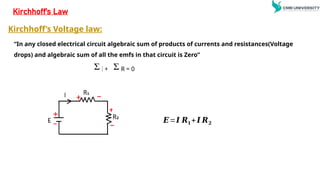
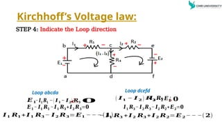
“In any closedelectrical circuit algebraic sum of products of currents and resistances(Voltage
drops) and algebraic sum of all the emfs in that circuit is Zero”
E + I R = 0
Kirchhoff’s Law
𝑬=𝑰 𝑹𝟏+ 𝑰 𝑹𝟐
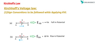
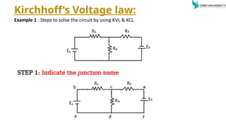
Kirchhoff’s Voltage law:
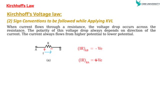
Kirchhoff’s Voltage law:
(2)Sign Conventions to be followed while Applying KVL
When current flows through a resistance, the voltage drop occurs across the
resistance. The polarity of this voltage drop always depends on direction of the
current. The current always flows from higher potential to lower potential.
Kirchhoff’s Law
(a)
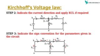
Kirchhoff’s Voltage law:
STEP2: Indicate the current direction and apply KCL if required
STEP 3: Indicate the sign convention for the parameters given in
the circuit
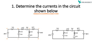
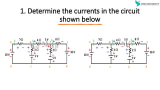
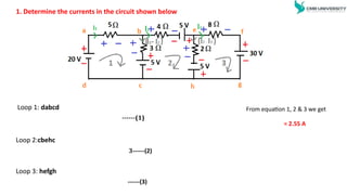
1. Determine thecurrents in the circuit shown below
Loop 1: dabcd
Loop 2:cbehc
Loop 3: hefgh
From equation 1, 2 & 3 we get
= 2.55 A
------(1)
3------(2)
------(3)
32.
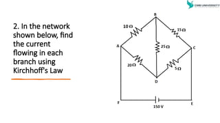
2. In thenetwork
shown below, find
the current
flowing in each
branch using
Kirchhoff's Law
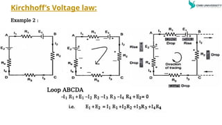
33.
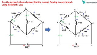
2.In the networkshown below, find the current flowing in each branch
using Kirchhoff's Law
34.
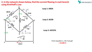
2. In thenetwork shown below, find the current flowing in each branch
using Kirchhoff's Law
Loop 1: ABDA
Loop 2: BCDB
Loop 3: ADCEFA
From equation 1, 2 & 3 we get
= 12.685 A
35.
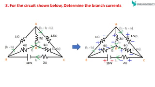
3. For thecircuit shown below, Determine the branch currents
36.
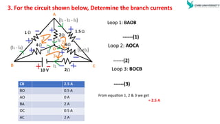
3. For thecircuit shown below, Determine the branch currents
Loop 1: BAOB
Loop 2: AOCA
Loop 3: BOCB
------(1)
------(2)
------(3)
From equation 1, 2 & 3 we get
= 2.5 A
CB 2.5 A
BO 0.5 A
AO 0 A
BA 2 A
OC 0.5 A
AC 2 A
37.
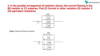
4. In theparallel arrangement of resistors shown, the current flowing in the
8Ω resistor is 2.5 amperes. Find (i) Current in other resistors (ii) resistor X
(iii) equivalent resistance
8
XΩ
40
25
4 A
8
XΩ
40
25
4 A
I1
I4
I3
I2
Step1: Name the branch currents
38.
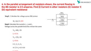
4. In theparallel arrangement of resistors shown, the current flowing in
the 8Ω resistor is 2.5 amperes. Find (i) Current in other resistors (ii) resistor X
(iii) equivalent resistance
Step2: Calculate the voltage across 8Ω resistor
Step3: Calculate the currents I2, I3 and I4
Voltage across the parallel branches remain the same
8I1=8x2.5=20V
V40=40I3=20
I3=0.5A
V25=25I4=20
I4=0.8A
I=I1+I2+I3+I4
4=2.5+I2+0.5+0.8
8
XΩ
40
25
4 A
39.
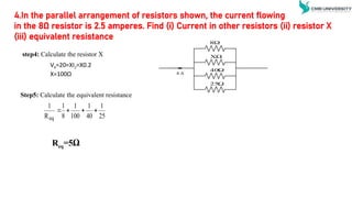
VX=20=XI2=X0.2
X=100Ω
step4: Calculate theresistor X
Step5: Calculate the equivalent resistance
Req=5Ω
25
1
40
1
100
1
8
1
R
1
eq
4.In the parallel arrangement of resistors shown, the current flowing
in the 8Ω resistor is 2.5 amperes. Find (i) Current in other resistors (ii) resistor X
(iii) equivalent resistance
8
XΩ
40
25
4 A
40.
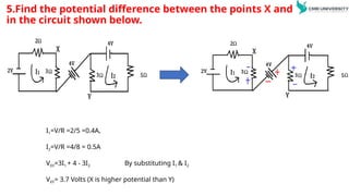
5.Find the potentialdifference between the points X and Y
in the circuit shown below.
I1=V/R =2/5 =0.4A,
I2=V/R =4/8 = 0.5A
VXY=3I1 + 4 - 3I2 By substituting I1 & I2
VXY= 3.7 Volts (X is higher potential than Y)
41.
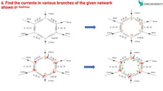
6. Find thecurrents in various branches of the given network
shown in below
42.
6. Find thecurrents in various branches of the given
network shown in below
Step1: Name the nodes and apply KCL at all the nodes
Step2: Apply KVL to the closed loop ABCDEFA,
-0.02I-0.02(I-80)-0.03(I+10)-0.02(I-140)-0.01(I-20)-0.01(I-100)=0
-0.11I+1.6-0.3+2.8+0.2+1=0
-0.11I= -5.3
I=48.18A
43.
6. Find thecurrents in various branches of the given network
shown in below
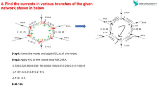
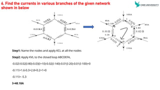
Step1: Name the nodes and apply KCL at all the nodes
Step2: Apply KVL to the closed loop ABCDEFA,
-0.02I-0.02(I-80)-0.03(I+10)-0.02(I-140)-0.01(I-20)-0.01(I-100)=0
-0.11I+1.6-0.3+2.8+0.2+1=0
-0.11I= -5.3
I=48.18A
1 0 0 A
8 0 A
9 0 A
1 5 0 A
1 2 0 A
8 0 A
02
.
0
01
.
0
44.
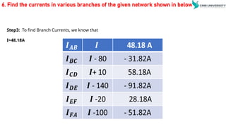
6. Find thecurrents in various branches of the given network shown in below
Step3: To find Branch Currents, we know that
I=48.18A
45.
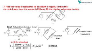
7. Find thevalue of resistance ‘R’ as shown in Figure, so that the
current drawn from the source is 250 mA. All the resistor values are in ohm.
Step1: Reduce the network as shown
+
-
5V
R
30
40
40
+
-
5V
30
40
R
40
40R
+
-
5V
30
R
40
80R
1600
+
-
5V
R
110
2800
2400R
48000
3
10
250x
x
110R
2800
2400R
48000
5
R=40 Ohm
V= IR (by ohms law)
46.
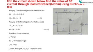
8.In the circuitshown below find the value of DC
current through load resistance(6 Ohm) using Kirchhoff’s
law
Applying Kirchoffs voltage law for the loop acdba
-84 + 12I1 + (I1+I2)6=0
18I1 + 6I2 – 84 = 0 ------ (I)
Applying Kirchoffs voltage law for the loop cfedc
- (I1+I2)6 - 3I2 + 21=0
-6I1 - 9I2 + 21 = 0 ----- (II)
By solving (I) and (II) we get
I2=-1amps
But I2=-1 in eq(II) we get
I1 = 5 amps
Current through RL = (I1+I2) = 5 + (-1) = 4 amps
47.
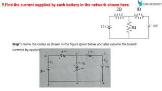
9.Find the currentsupplied by each battery in the network shown here.
Step1: Name the nodes as shown in the figure given below and also assume the branch
currents by applying KCL.
3
30V 20V
2
1
48.
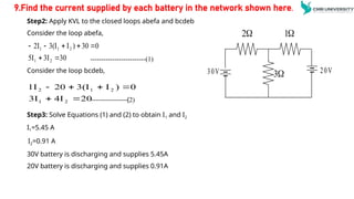
Step2: Apply KVLto the closed loops abefa and bcdeb
Consider the loop abefa,
-------------------------(1)
Consider the loop bcdeb,
Step3: Solve Equations (1) and (2) to obtain I1 and I2
I1=5.45 A
I2=0.91 A
30V battery is discharging and supplies 5.45A
20V battery is discharging and supplies 0.91A
30
3I
5I
0
30
)
I
3(I
2I
2
1
2
1
1
20
4I
3I
0
)
I
3(I
20
1I
2
1
2
1
2
-----------------(2)
9.Find the current supplied by each battery in the network shown here.
3
30V 20V
2
1