Download as PDF, PPTX
![Circuit Theory
(EE102)
Lecture 1(a)
Basic Concepts & Basic Laws
Text Book:
Fundamentals of Electric Circuits (4th Ed/3rd Ed) By Alexander & Sadiku. McGraw-Hill [CH1]
Faculty of Engineering
Page 1](https://image.slidesharecdn.com/lecture1acompatibilitymode-130523045820-phpapp02/85/Lecture-1a-compatibility-mode-1-320.jpg)


![Text Book:
Fundamentals of Electric Circuits (4th Ed/3rd Ed) By Alexander & Sadiku. McGraw-Hill [CH2]
Faculty of Engineering
Page 16
Basic Laws](https://image.slidesharecdn.com/lecture1acompatibilitymode-130523045820-phpapp02/85/Lecture-1a-compatibility-mode-16-320.jpg)


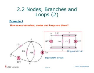


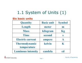
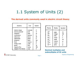
This document provides an overview of Circuit Theory (EE102) Lecture 1, covering basic concepts in electric circuits including: - Systems of units used to measure electric properties like current and voltage. - Basic circuit elements like resistors, sources, and nodes and branches. - Kirchhoff's laws and techniques for analyzing series and parallel circuits. - Transformations between wye and delta networks. Worked examples are provided to illustrate applying concepts like Ohm's law, Kirchhoff's laws, and calculating equivalent resistances for series and parallel circuits.