The document discusses different types of amplitude modulation (AM) including:
1) Double sideband AM which produces a signal with power at the carrier frequency and two adjacent sidebands, each equal in bandwidth to the modulating signal.
2) Single sideband modulation which completely suppresses either the carrier or one sideband, improving bandwidth efficiency at the cost of increased complexity.
3) On-off keying AM which represents binary data as the presence or absence of a carrier wave, commonly used to transmit Morse code.
The modulation index measures the extent of amplitude variation around the unmodulated carrier level, relating the variation in carrier amplitude to avoid distortion.
In this presentation, we tried our best to explain the two basic types of Modulation that are Amplitude modulation and Frequency modulation. We hope you find this PPT useful.
Modulation
In the modulation process, some characteristic of a high-frequency carrier signal (bandpass), is changed according to the instantaneous amplitude of the information (baseband) signal.
Comparative Study and Performance Analysis of different Modulation Techniques...Souvik Das
Make a comparative study and performance analysis of different modulation
techniques which shows graphically and comparatively results like Bandwidth,
Energy and Power Efficiency of AM, DSB-SC, SSB and SSB-SC
This is all about MODULATION, AMPLITUDE MODULATION, AND AM DEMODULATION, Techniques
By_ IMTIAZ ALI AHMED
B.Tech Student
Siliguri Institute of Technology(ECE)
ALTITUDE. Vertical distance of an aircraft or object above a given reference, such as ground or sea level.
AMPLIFIER. An electronic device used to increase signal magnitude or power.
AMPLITUDE MODULATION (AM). A method of impressing a message upon a carrier signal by causing the carrier amplitude to vary proportionally to the message waveform.
ANTENNA SYSTEM. Routes RF energy from the transmitter, radiates the energy into space, receives echoes, and routes the echoes to the receiver.
A presentation prepared by my friend's friend. I have done no editing at all, I'm just uploading the presentation as it is.
RF Carrier oscillator
To generate the carrier signal.
Usually a crystal-controlled oscillator is used.
Buffer amplifier
Low gain, high input impedance linear amplifier.
To isolate the oscillator from the high power amplifiers.
Modulator : can use either emitter collector modulation
Intermediate and final power amplifiers (pull-push modulators)
Required with low-level transmitters to maintain symmetry in the AM envelope
Coupling network
Matches output impedance of the final amplifier to the transmission line/antenn
Applications are in low-power, low-capacity systems : wireless intercoms, remote control units, pagers and short-range walkie-talkie
Modulating signal is processed similarly as in low-level transmitter except for the addition of power amplifier
Power amplifier
To provide higher power modulating signal necessary to achieve 100% modulation (carrier power is maximum at the high-level modulation point).
Same circuit as low-level transmitter for carrier oscillator, buffer and driver but with addition of power amplifier
LF Energy Webinar: Electrical Grid Modelling and Simulation Through PowSyBl -...DanBrown980551
Do you want to learn how to model and simulate an electrical network from scratch in under an hour?
Then welcome to this PowSyBl workshop, hosted by Rte, the French Transmission System Operator (TSO)!
During the webinar, you will discover the PowSyBl ecosystem as well as handle and study an electrical network through an interactive Python notebook.
PowSyBl is an open source project hosted by LF Energy, which offers a comprehensive set of features for electrical grid modelling and simulation. Among other advanced features, PowSyBl provides:
- A fully editable and extendable library for grid component modelling;
- Visualization tools to display your network;
- Grid simulation tools, such as power flows, security analyses (with or without remedial actions) and sensitivity analyses;
The framework is mostly written in Java, with a Python binding so that Python developers can access PowSyBl functionalities as well.
What you will learn during the webinar:
- For beginners: discover PowSyBl's functionalities through a quick general presentation and the notebook, without needing any expert coding skills;
- For advanced developers: master the skills to efficiently apply PowSyBl functionalities to your real-world scenarios.
Epistemic Interaction - tuning interfaces to provide information for AI supportAlan Dix
Paper presented at SYNERGY workshop at AVI 2024, Genoa, Italy. 3rd June 2024
https://alandix.com/academic/papers/synergy2024-epistemic/
As machine learning integrates deeper into human-computer interactions, the concept of epistemic interaction emerges, aiming to refine these interactions to enhance system adaptability. This approach encourages minor, intentional adjustments in user behaviour to enrich the data available for system learning. This paper introduces epistemic interaction within the context of human-system communication, illustrating how deliberate interaction design can improve system understanding and adaptation. Through concrete examples, we demonstrate the potential of epistemic interaction to significantly advance human-computer interaction by leveraging intuitive human communication strategies to inform system design and functionality, offering a novel pathway for enriching user-system engagements.
GraphRAG is All You need? LLM & Knowledge GraphGuy Korland
Guy Korland, CEO and Co-founder of FalkorDB, will review two articles on the integration of language models with knowledge graphs.
1. Unifying Large Language Models and Knowledge Graphs: A Roadmap.
https://arxiv.org/abs/2306.08302
2. Microsoft Research's GraphRAG paper and a review paper on various uses of knowledge graphs:
https://www.microsoft.com/en-us/research/blog/graphrag-unlocking-llm-discovery-on-narrative-private-data/
JMeter webinar - integration with InfluxDB and GrafanaRTTS
Watch this recorded webinar about real-time monitoring of application performance. See how to integrate Apache JMeter, the open-source leader in performance testing, with InfluxDB, the open-source time-series database, and Grafana, the open-source analytics and visualization application.
In this webinar, we will review the benefits of leveraging InfluxDB and Grafana when executing load tests and demonstrate how these tools are used to visualize performance metrics.
Length: 30 minutes
Session Overview
-------------------------------------------
During this webinar, we will cover the following topics while demonstrating the integrations of JMeter, InfluxDB and Grafana:
- What out-of-the-box solutions are available for real-time monitoring JMeter tests?
- What are the benefits of integrating InfluxDB and Grafana into the load testing stack?
- Which features are provided by Grafana?
- Demonstration of InfluxDB and Grafana using a practice web application
To view the webinar recording, go to:
https://www.rttsweb.com/jmeter-integration-webinar
State of ICS and IoT Cyber Threat Landscape Report 2024 previewPrayukth K V
The IoT and OT threat landscape report has been prepared by the Threat Research Team at Sectrio using data from Sectrio, cyber threat intelligence farming facilities spread across over 85 cities around the world. In addition, Sectrio also runs AI-based advanced threat and payload engagement facilities that serve as sinks to attract and engage sophisticated threat actors, and newer malware including new variants and latent threats that are at an earlier stage of development.
The latest edition of the OT/ICS and IoT security Threat Landscape Report 2024 also covers:
State of global ICS asset and network exposure
Sectoral targets and attacks as well as the cost of ransom
Global APT activity, AI usage, actor and tactic profiles, and implications
Rise in volumes of AI-powered cyberattacks
Major cyber events in 2024
Malware and malicious payload trends
Cyberattack types and targets
Vulnerability exploit attempts on CVEs
Attacks on counties – USA
Expansion of bot farms – how, where, and why
In-depth analysis of the cyber threat landscape across North America, South America, Europe, APAC, and the Middle East
Why are attacks on smart factories rising?
Cyber risk predictions
Axis of attacks – Europe
Systemic attacks in the Middle East
Download the full report from here:
https://sectrio.com/resources/ot-threat-landscape-reports/sectrio-releases-ot-ics-and-iot-security-threat-landscape-report-2024/
UiPath Test Automation using UiPath Test Suite series, part 3DianaGray10
Welcome to UiPath Test Automation using UiPath Test Suite series part 3. In this session, we will cover desktop automation along with UI automation.
Topics covered:
UI automation Introduction,
UI automation Sample
Desktop automation flow
Pradeep Chinnala, Senior Consultant Automation Developer @WonderBotz and UiPath MVP
Deepak Rai, Automation Practice Lead, Boundaryless Group and UiPath MVP
GDG Cloud Southlake #33: Boule & Rebala: Effective AppSec in SDLC using Deplo...James Anderson
Effective Application Security in Software Delivery lifecycle using Deployment Firewall and DBOM
The modern software delivery process (or the CI/CD process) includes many tools, distributed teams, open-source code, and cloud platforms. Constant focus on speed to release software to market, along with the traditional slow and manual security checks has caused gaps in continuous security as an important piece in the software supply chain. Today organizations feel more susceptible to external and internal cyber threats due to the vast attack surface in their applications supply chain and the lack of end-to-end governance and risk management.
The software team must secure its software delivery process to avoid vulnerability and security breaches. This needs to be achieved with existing tool chains and without extensive rework of the delivery processes. This talk will present strategies and techniques for providing visibility into the true risk of the existing vulnerabilities, preventing the introduction of security issues in the software, resolving vulnerabilities in production environments quickly, and capturing the deployment bill of materials (DBOM).
Speakers:
Bob Boule
Robert Boule is a technology enthusiast with PASSION for technology and making things work along with a knack for helping others understand how things work. He comes with around 20 years of solution engineering experience in application security, software continuous delivery, and SaaS platforms. He is known for his dynamic presentations in CI/CD and application security integrated in software delivery lifecycle.
Gopinath Rebala
Gopinath Rebala is the CTO of OpsMx, where he has overall responsibility for the machine learning and data processing architectures for Secure Software Delivery. Gopi also has a strong connection with our customers, leading design and architecture for strategic implementations. Gopi is a frequent speaker and well-known leader in continuous delivery and integrating security into software delivery.
Transcript: Selling digital books in 2024: Insights from industry leaders - T...BookNet Canada
The publishing industry has been selling digital audiobooks and ebooks for over a decade and has found its groove. What’s changed? What has stayed the same? Where do we go from here? Join a group of leading sales peers from across the industry for a conversation about the lessons learned since the popularization of digital books, best practices, digital book supply chain management, and more.
Link to video recording: https://bnctechforum.ca/sessions/selling-digital-books-in-2024-insights-from-industry-leaders/
Presented by BookNet Canada on May 28, 2024, with support from the Department of Canadian Heritage.
Kubernetes & AI - Beauty and the Beast !?! @KCD Istanbul 2024Tobias Schneck
As AI technology is pushing into IT I was wondering myself, as an “infrastructure container kubernetes guy”, how get this fancy AI technology get managed from an infrastructure operational view? Is it possible to apply our lovely cloud native principals as well? What benefit’s both technologies could bring to each other?
Let me take this questions and provide you a short journey through existing deployment models and use cases for AI software. On practical examples, we discuss what cloud/on-premise strategy we may need for applying it to our own infrastructure to get it to work from an enterprise perspective. I want to give an overview about infrastructure requirements and technologies, what could be beneficial or limiting your AI use cases in an enterprise environment. An interactive Demo will give you some insides, what approaches I got already working for real.
Kubernetes & AI - Beauty and the Beast !?! @KCD Istanbul 2024
Am5
1. NATIONAL COLLEGE OF SCIENCE AND TECHNOLOGY
Amafel Bldg. Aguinaldo Highway Dasmariñas City, Cavite
Assignment # 2
AMPLITUDE MODULATION
(Types of Amplitude Modulation)
(Power in Amplitude Modulation)
(Modulation Index)
Alido, Ronald June 29,2011
Communications 1 / BSECE 41A1 Score:
Eng'r. Grace Ramones
Instructor
2. Amplitude Modulation
Varying the voltage of a carrier or a direct current in order to transmit analog or digital
data. Amplitude modulation (AM) is the oldest method of transmitting human voice
electronically. In an analog telephone conversation, the voice waves on both sides are
modulating the voltage of the direct current loop connected to them by the telephone
company.
Modulate a Carrier
Amplitude modulation (AM) is also widely used to alter a carrier wave to transmit data.
For example, in AM radio, the voltage (amplitude) of a carrier with a fixed center
frequency (the station's channel) is varied (modulated) by the analog audio signal.
AM is also used for digital data. In quadrature amplitude modulation (QAM), both
amplitude and phase modulation are used to create different binary states for
transmission (see QAM). AM is also used to modulate light waves in optical fibers.
In AM modulation, the voltage (amplitude) of the carrier is varied by the incoming signal.
In this example, the modulating wave implies an analog signal.
Digital Amplitude
Vary the Amplitude
Shift Keying (ASK)
For digital signals, amplitude shift keying (ASK) uses two voltage levels for 0 and 1 as in
this example.
3. Types of amplitude modulation
In radio communication, a continuous wave radio-frequency signal (a sinusoidal carrier
wave) has its amplitude modulated by an audio waveform before being transmitted.
In the frequency domain, amplitude modulation produces a signal with power
concentrated at the carrier frequency and in two adjacent sidebands. Each sideband is
equal in bandwidth to that of the modulating signal and is a mirror image of the other.
Amplitude modulation that results in two sidebands and a carrier is often called double-
sideband amplitude modulation (DSB-AM). Amplitude modulation is inefficient in terms
of power usage. At least two-thirds of the power is concentrated in the carrier signal,
which carries no useful information (beyond the fact that a signal is present).
To increase transmitter efficiency, the carrier can be removed (suppressed) from the
AM signal. This produces a reduced-carrier transmission or double-sideband
suppressed-carrier (DSBSC) signal. A suppressed-carrier amplitude modulation
scheme is three times more power-efficient than traditional DSB-AM. If the carrier is
only partially suppressed, a double-sideband reduced-carrier (DSBRC) signal results.
DSBSC and DSBRC signals need their carrier to be regenerated (by a beat frequency
oscillator, for instance) to be demodulated using conventional techniques.
Improved bandwidth efficiency is achieved—at the expense of increased transmitter and
receiver complexity—by completely suppressing both the carrier and one of the
sidebands. This is single-sideband modulation, widely used in amateur radio due to its
efficient use of both power and bandwidth.
A simple form of AM often used for digital communications is on-off keying, a type of
amplitude-shift keying by which binary data is represented as the presence or absence
of a carrier wave. This is commonly used at radio frequencies to transmit Morse code,
referred to as continuous wave (CW) operation.
ITU designations
In 1982, the International Telecommunication Union (ITU) designated the various types
of amplitude modulation as follows:
Designation Description
A3E double-sideband full-carrier - the basic AM modulation scheme
R3E single-sideband reduced-carrier
H3E single-sideband full-carrier
J3E single-sideband suppressed-carrier
B8E independent-sideband emission
C3F vestigial-sideband
Lincompex linked compressor and expander
4. Power in Amplitude Modulation
o The envelope, or boundary, of the amplitude modulated signal embeds the
information bearing signal.
o The total power of the transmitted signal varies with the modulating signal,
whereas the carrier power remains constant.
o The total wave power which varies in amplitude, and not the carrier power. The
carrier power in an amplitude modulated system remains constant.
5. Modulation index
It can be defined as the measure of extent of amplitude variation about an unmodulated
maximum carrier. As with other modulation indices, in AM, this quantity, also called
modulation depth, indicates by how much the modulated variable varies around its
'original' level. For AM, it relates to the variations in the carrier amplitude and is defined
as:
where and were introduced above.
So if h = 0.5, the carrier amplitude varies by 50% above and below its unmodulated
level, and for h = 1.0 it varies by 100%. To avoid distortion in the A3E transmission
mode, modulation depth greater than 100% must be avoided. Practical transmitter
systems will usually incorporate some kind of limiter circuit, such as a VOGAD, to
ensure this. However, AM demodulators can be designed to detect the inversion (or 180
degree phase reversal) that occurs when modulation exceeds 100% and automatically
correct for this effect.[citation needed]
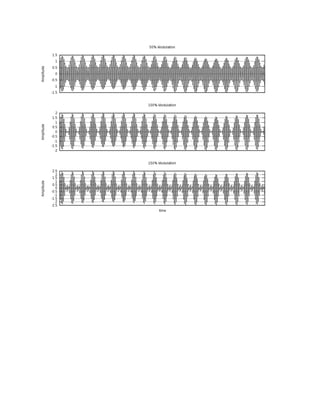
Variations of modulated signal with percentage modulation are shown below. In each
image, the maximum amplitude is higher than in the previous image. Note that the scale
changes from one image to the next.