Download to read offline
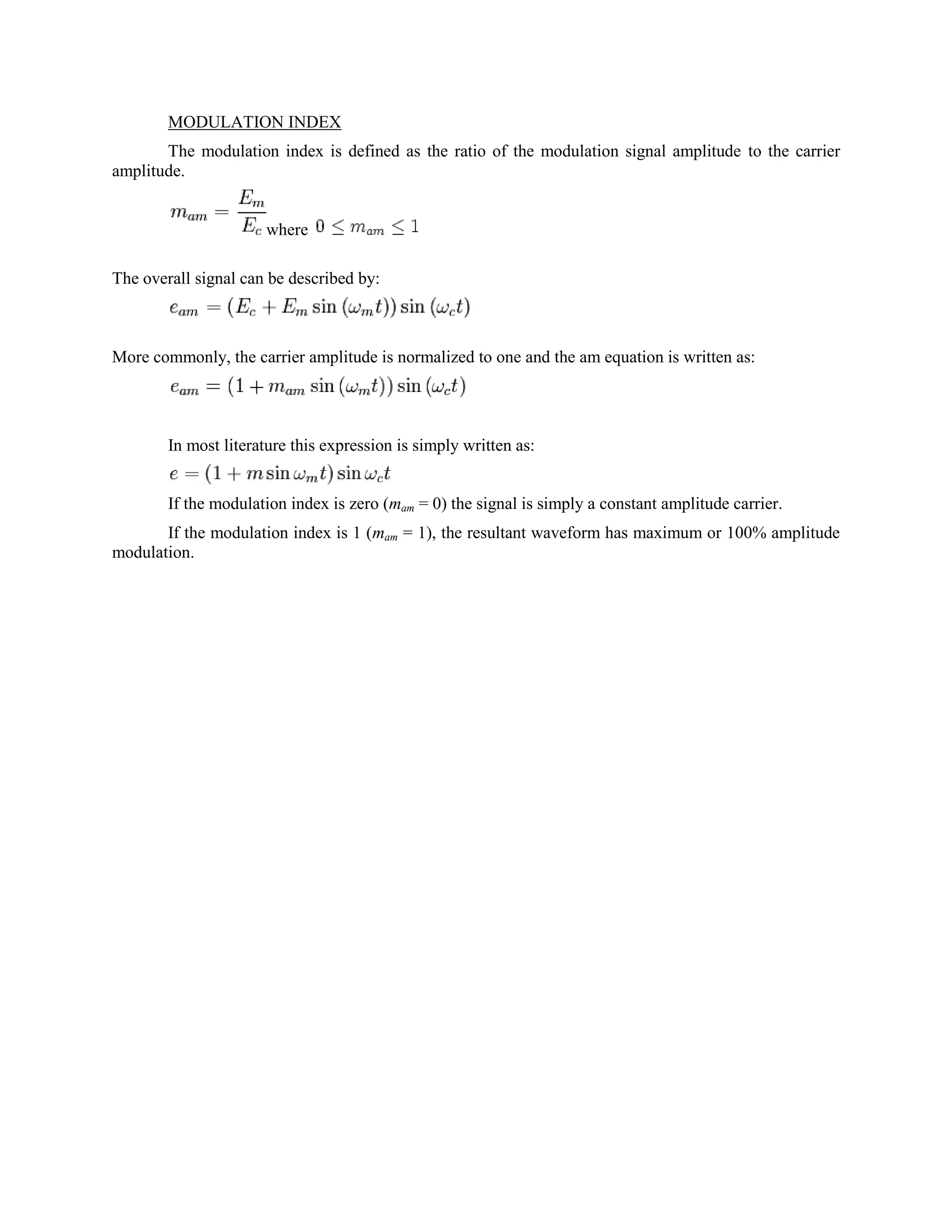

This document discusses types of amplitude modulation (AM) used in radio communications, including double sideband (DSB), single sideband (SSB), and vestigial sideband modulation. It explains that AM involves modulating a high frequency carrier signal with lower frequency audio/voice signals in order to transmit electromagnetic radiation. The power in an AM signal varies according to the audio signal rather than the carrier power remaining constant. The modulation index is defined as the ratio of the audio signal amplitude to the carrier amplitude.


![Coded Agents – with UiPath SDK + LangGraph [Virtual Hands-on Workshop]](https://cdn.slidesharecdn.com/ss_thumbnails/codedagentsdeck-251215155422-5497c599-thumbnail.jpg?width=640&height=640&fit=bounds)


