Downloaded 147 times


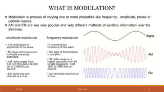
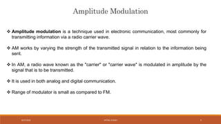
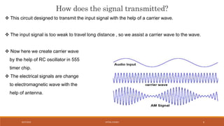
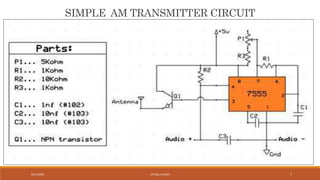
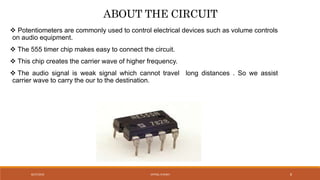
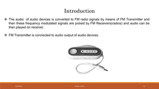
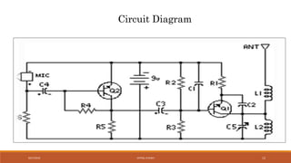
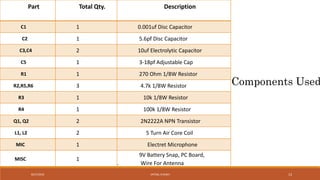
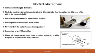


The document discusses amplitude modulation (AM) and frequency modulation (FM) transmitters. It provides a circuit diagram and explanation of a simple AM transmitter that uses a 555 timer chip to generate a carrier wave. It then discusses an FM transmitter circuit, including its components, working principle, and pros and cons. The FM transmitter involves preamplification of an audio signal, oscillation to modulate the signal's frequency, and power amplification of the modulated signal for transmission.


![[HUBDAY] UDECAM, Quels nouveaux challenges pour les agences médias ?](https://cdn.slidesharecdn.com/ss_thumbnails/udecam-nouveauxchallenges-150420033510-conversion-gate02-thumbnail.jpg?width=640&height=640&fit=bounds)