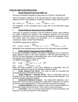
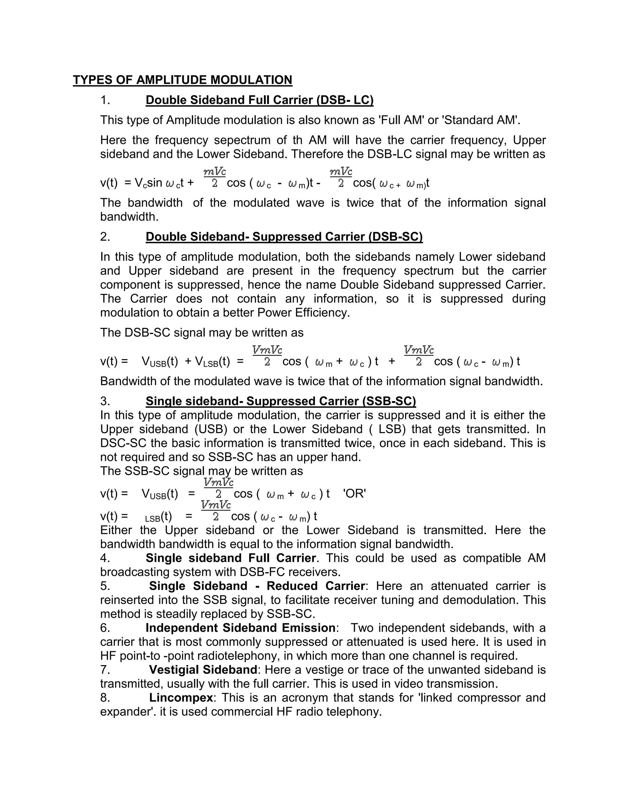
The CMO Survey - Highlights and Insights Report - Spring 2024
Am11
1. TYPES OF AMPLITUDE MODULATION
1. Double Sideband Full Carrier (DSB- LC)
This type of Amplitude modulation is also known as 'Full AM' or 'Standard AM'.
Here the frequency sepectrum of th AM will have the carrier frequency, Upper
sideband and the Lower Sideband. Therefore the DSB-LC signal may be written as
v(t) = Vcsin ct + cos ( c - m)t - cos( c+ m)t
The bandwidth of the modulated wave is twice that of the information signal
bandwidth.
2. Double Sideband- Suppressed Carrier (DSB-SC)
In this type of amplitude modulation, both the sidebands namely Lower sideband
and Upper sideband are present in the frequency spectrum but the carrier
component is suppressed, hence the name Double Sideband suppressed Carrier.
The Carrier does not contain any information, so it is suppressed during
modulation to obtain a better Power Efficiency.
The DSB-SC signal may be written as
v(t) = VUSB(t) + VLSB(t) = cos ( m + c )t + cos ( c - m) t
Bandwidth of the modulated wave is twice that of the information signal bandwidth.
3. Single sideband- Suppressed Carrier (SSB-SC)
In this type of amplitude modulation, the carrier is suppressed and it is either the
Upper sideband (USB) or the Lower Sideband ( LSB) that gets transmitted. In
DSC-SC the basic information is transmitted twice, once in each sideband. This is
not required and so SSB-SC has an upper hand.
The SSB-SC signal may be written as
v(t) = VUSB(t) = cos ( m + c )t 'OR'
v(t) = LSB(t) = cos ( c - m) t
Either the Upper sideband or the Lower Sideband is transmitted. Here the
bandwidth bandwidth is equal to the information signal bandwidth.
4. Single sideband Full Carrier. This could be used as compatible AM
broadcasting system with DSB-FC receivers.
5. Single Sideband - Reduced Carrier: Here an attenuated carrier is
reinserted into the SSB signal, to facilitate receiver tuning and demodulation. This
method is steadily replaced by SSB-SC.
6. Independent Sideband Emission: Two independent sidebands, with a
carrier that is most commonly suppressed or attenuated is used here. It is used in
HF point-to -point radiotelephony, in which more than one channel is required.
7. Vestigial Sideband: Here a vestige or trace of the unwanted sideband is
transmitted, usually with the full carrier. This is used in video transmission.
8. Lincompex: This is an acronym that stands for 'linked compressor and
expander'. it is used commercial HF radio telephony.
2. POWER IN AMPLITUDE MODULATION
In AM wave the transmission carriers contain most of the power
The utilisation of power by an amplitude modulated signal is very poor. When the
carrier is modulated sidebands appear at either side of the carrier in its frequency
spectrum. Each sideband contains the information about the audio modulation. To look
at how the signal is made up and the relative powers take the simplified case where the
1 kHz tone is modulating the carrier. In this case two signals will be found 1 kHz either
side of the main carrier. When the carrier is fully modulated i.e. 100% the amplitude of
the modulation is equal to half that of the main carrier, i.e. the sum of the powers of the
sidebands is equal to half that of the carrier. This means that each sideband is just a
quarter of the total power. In other words for a transmitter with a 100 watt carrier, the
total sideband power would be 50 watts and each individual sideband would be 25
watts.
3. MODULATION INDEX
It is often necessary to define the level of modulation that is applied to a signal. A factor
or index known as the modulation index is used for this. When expressed as a
percentage it is the same as the depth of modulation. In other words it can be
expressed as:
M = (RMS value of modulating signal) / (RMS value of unmodulated signal)
The value of the modulation index must not be allowed to exceed one (i.e. 100 % in
terms of the depth of modulation) otherwise the envelope becomes distorted and the
signal will "splatter" either side of the wanted channel, causing interference and
annoyance to other users.
Amplitude modulation requires a high frequency constant carrier and a low frequency
modulation signal.
4. AMPLITUDE MODULATION
Modulation is the process of varying a higher frequency carrier wave to transmit
information. Though it is theoretically possible to transmit baseband signals (or
information) without modulating it, it is far more efficient to send data by modulating it
onto a higher frequency "carrier wave."
Amplitude modulation is a type of modulation where the amplitude of the carrier signal is
varied in accordance with the information bearing signal.
The envelope, or boundary, of the amplitude modulated signal embeds the information
bearing signal. A nonlinear device is used to combine the carrier and the modulating
signal to generate an amplitude modulated signal. The output of the nonlinear device
consists of discrete upper and lower sidebands. The output of a nonlinear device does
not vary in direct proportion with the input.
AM or amplitude modulation is used for modulating a radio signal to carry sound or
other information.
5. NATIONAL COLLEGE OF SCIENCE AND TECHNOLOGY
Amafel Bldg. Aguinaldo Highway Dasmariñas City, Cavite
Assignment # 2
AMPLITUDE MODULATION
(Types of Amplitude Modulation)
(Power in Amplitude Modulation)
(Modulation Index)
Lasco, Ben Rajnish E. June 29,2011
Communications 1 / BSECE 41A1 Score:
Eng'r. Grace Ramones
Instructor