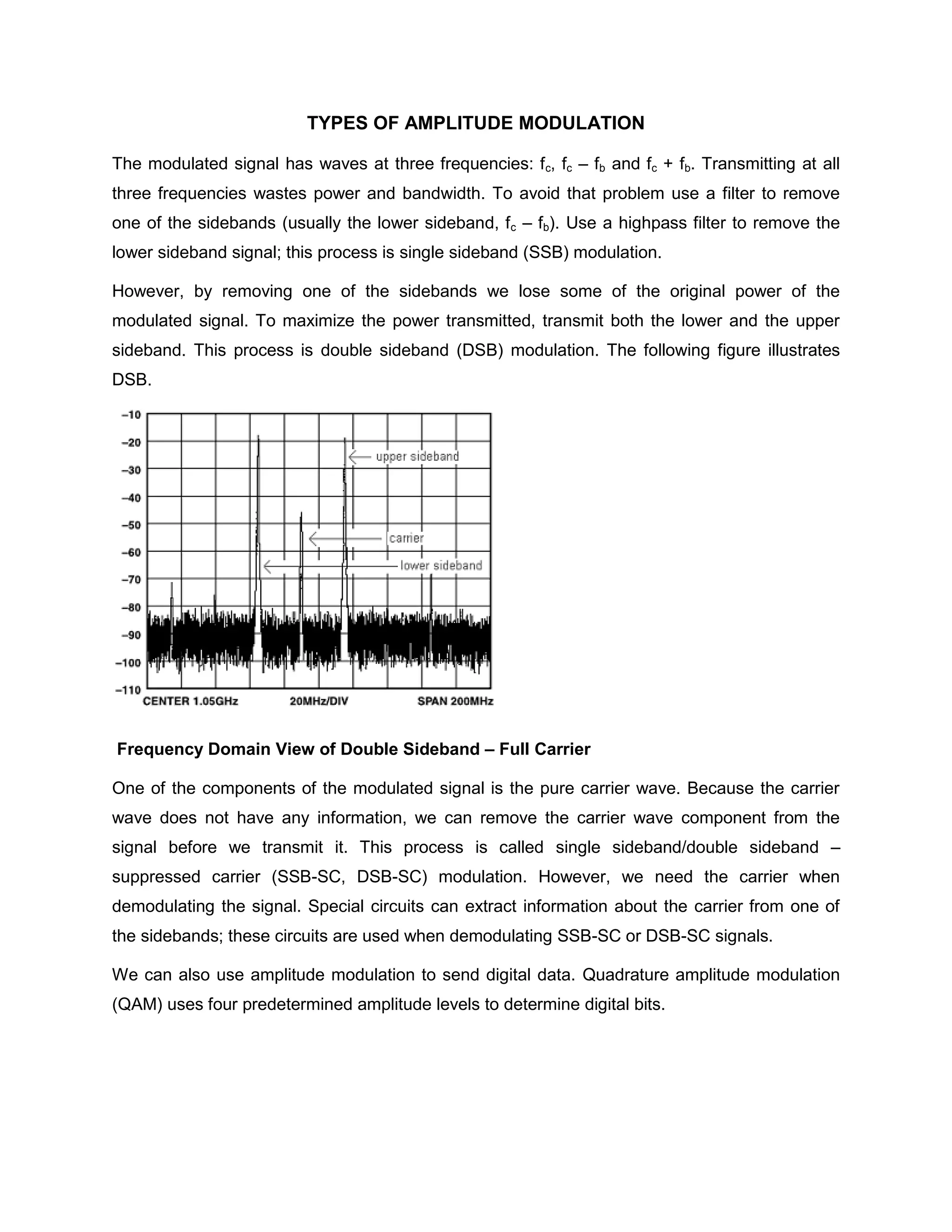
NATIONAL COLLEGE OF SCIENCE AND TECHNOLOGY
                       Amafel Bldg. Aguinaldo Highway Dasmariñas City, Cavite


                                   Assignment # 2

                            AMPLITUDE MODULATION
                               Types of Amplitude Modulation

                               Power in Amplitude Modulation

                                     Modulation Index


Cauan, Sarah Krystelle P.                                              June 29, 2011

Communications 1 / BSECE 41A1                                          Score:


                                   Eng'r. Grace Ramones
                                         Instructor
AMPLITUDE MODULATION

Modulation is the process of varying a higher frequency carrier wave to transmit information.
Though it is theoretically possible to transmit baseband signals (or information) without
modulating it, it is far more efficient to send data by modulating it onto a higher frequency
"carrier wave." Higher frequency waves require smaller antennas, use the available bandwidth
more efficiently, and are flexible enough to carry different types of data. AM radio stations
transmit audio signals, which range from 20 Hz to 20 kHz, using carrier waves that range from
500 kHz to 1.7 MHz. If we were to transmit audio signals directly we would need an antenna
that is around 10,000 km! Modulation techniques can be broadly divided into analog modulation
and digital modulation. Amplitude modulation (AM) is one form of analog modulation.
Amplitude modulation is a type of modulation where the amplitude of the carrier signal is
varied in accordance with the information bearing signal.

The envelope, or boundary, of the amplitude modulated signal embeds the information bearing
signal. A nonlinear device is used to combine the carrier and the modulating signal to generate
an amplitude modulated signal. The output of the nonlinear device consists of discrete upper
and lower sidebands. The output of a nonlinear device does not vary in direct proportion with
the input.

AM or amplitude modulation is used for modulating a radio signal to carry sound or other
information.
TYPES OF AMPLITUDE MODULATION

The modulated signal has waves at three frequencies: f c, fc – fb and fc + fb. Transmitting at all
three frequencies wastes power and bandwidth. To avoid that problem use a filter to remove
one of the sidebands (usually the lower sideband, fc – fb). Use a highpass filter to remove the
lower sideband signal; this process is single sideband (SSB) modulation.

However, by removing one of the sidebands we lose some of the original power of the
modulated signal. To maximize the power transmitted, transmit both the lower and the upper
sideband. This process is double sideband (DSB) modulation. The following figure illustrates
DSB.


Frequency Domain View of Double Sideband – Full Carrier

One of the components of the modulated signal is the pure carrier wave. Because the carrier
wave does not have any information, we can remove the carrier wave component from the
signal before we transmit it. This process is called single sideband/double sideband –
suppressed carrier (SSB-SC, DSB-SC) modulation. However, we need the carrier when
demodulating the signal. Special circuits can extract information about the carrier from one of
the sidebands; these circuits are used when demodulating SSB-SC or DSB-SC signals.

We can also use amplitude modulation to send digital data. Quadrature amplitude modulation
(QAM) uses four predetermined amplitude levels to determine digital bits.
Double Sideband Full Carrier (DSB- LC)

This type of Amplitude modulation is also known as 'Full AM' or 'Standard AM'.

Here the frequency sepectrum of th AM will have the carrier frequency, Upper sideband and the
Lower Sideband. Therefore the DSB-LC signal may be written as


v(t) = Vcsin      ct   +   cos (    c   -       m)t      -             cos(    c+   m)t


The bandwidth of the modulated wave is twice that of the information signal bandwidth.

Double Sideband- Suppressed Carrier (DSB-SC)

In this type of amplitude modulation, both the sidebands namely Lower sideband and Upper
sideband are present in the frequency spectrum but the carrier component is suppressed,
hence the name Double Sideband suppressed Carrier. The Carrier does not contain any
information, so it is suppressed during modulation to obtain a better Power Efficiency.

The DSB-SC signal may be written as


v(t) =   VUSB(t) + VLSB(t) =            cos (                m   +     c    )t +          cos (   c   -   m)   t

Bandwidth of the modulated wave is twice that of the information signal bandwidth.

Single sideband- Suppressed Carrier (SSB-SC)
In this type of amplitude modulation, the carrier is suppressed and it is either the Upper
sideband (USB) or the Lower Sideband ( LSB) that gets transmitted. In DSC-SC the basic
information is transmitted twice, once in each sideband. This is not required and so SSB-SC has
an upper hand.
The SSB-SC signal may be written as

v(t) =   VUSB(t) =          cos (       m   +        c   )t          'OR'

v(t) =   LSB(t)        =   cos (    c   -       m)   t
Either the Upper sideband or the Lower Sideband is transmitted. Here the bandwidth bandwidth
is equal to the information signal bandwidth.


Apart from these three, the other types of amplitude modulations are:

Single sideband Full Carrier. This could be used as compatible AM broadcasting system with
DSB-FC receivers.
Single Sideband - Reduced Carrier: Here an attenuated carrier is reinserted into the SSB
signal, to facilitate receiver tuning and demodulation. This method is steadily replaced by SSB-
SC.
Independent Sideband Emission: Two independent sidebands, with a carrier that is most
commonly suppressed or attenuated is used here. It is used in HF point-to -point
radiotelephony, in which more than one channel is required.
Vestigial Sideband: Here a vestige or trace of the unwanted sideband is transmitted, usually
with the full carrier. This is used in video transmission.
Lincompex: This is an acronym that stands for 'linked compressor and expander'. it is used
commercial HF radio telephony.

Designation    Description

A3E    double-sideband full-carrier - the basic AM modulation scheme

R3E    single-sideband reduced-carrier

H3E    single-sideband full-carrier

J3E    single-sideband suppressed-carrier

B8E    independent-sideband emission

C3F    vestigial-sideband
POWER IN AMPLITUDE MODULATION

Even with 100% modulation the utilisation of power by an amplitude modulated signal is very
poor. When the carrier is modulated sidebands appear at either side of the carrier in its
frequency spectrum. Each sideband contains the information about the audio modulation. To
look at how the signal is made up and the relative powers take the simplified case where the 1
kHz tone is modulating the carrier. In this case two signals will be found 1 kHz either side of the
main carrier. When the carrier is fully modulated i.e. 100% the amplitude of the modulation is
equal to half that of the main carrier, i.e. the sum of the powers of the sidebands is equal to half
that of the carrier. This means that each sideband is just a quarter of the total power. In other
words for a transmitter with a 100 watt carrier, the total sideband power would be 50 watts and
each individual sideband would be 25 watts. During the modulation process the carrier
power remains constant. It is only needed as a reference during the demodulation process.
This means that the sideband power is the useful section of the signal, and this corresponds to
(50 / 150) x 100%, or only 33% of the total power transmitted.

Not only is AM wasteful in terms of power, it is also not very efficient in its use of spectrum. If
the 1 kHz tone is replaced by a typical audio signal made up of a variety of sounds with different
frequencies then each frequency will be present in each sideband. Accordingly the sidebands
spread out either side of the carrier as shown and the total bandwidth used is equal to twice the
top frequency that is transmitted. In the crowded conditions found on many of the short wave
bands today, this is a waste of space, and other modes of transmission which take up less
space are often used.
MODULATION INDEX

It is often necessary to define the level of modulation that is applied to a signal. A factor or index
known as the modulation index is used for this. When expressed as a percentage it is the same
as the depth of modulation. In other words it can be expressed as:

M = (RMS value of modulating signal) / (RMS value of unmodulated signal)

The value of the modulation index must not be allowed to exceed one (i.e. 100 % in terms of the
depth of modulation) otherwise the envelope becomes distorted and the signal will "splatter"
either side of the wanted channel, causing interference and annoyance to other users.

Amplitude modulation requires a high frequency constant carrier and a low frequency
modulation signal.

A sine wave carrier is of the form

A sine wave modulation signal is of the form

The high frequency carrier takes on the shape of the lower frequency modulation signal, forming
what is called a modulation envelope.

The modulation index is defined as the ratio of the modulation signal amplitude to the
carrier amplitude.


              where

The overall signal can be described by:


More commonly, the carrier amplitude is normalized to one and the am equation is written as:


In most literature this expression is simply written as:


If the modulation index is zero (mam = 0) the signal is simply a constant amplitude carrier.

If the modulation index is 1 (mam = 1), the resultant waveform has maximum or 100% amplitude
modulation.
Sidebands

Expanding the normalized AM equation:


we obtain:


where: sinωct represents the carrier


                  represents the lower sideband


                 represents the upper sideband


The sidebands are centered on the carrier frequency. They are the sum and difference
frequencies of the carrier and modulation signals. In the above example, they are just single
frequencies, but normally the baseband modulation signal is a range of frequencies and hence
two bands are formed.

As a side point, note that multiplication in the time domain causes addition and subtraction in
the frequency domain.

Amsarah

  • 1.
    NATIONAL COLLEGE OFSCIENCE AND TECHNOLOGY Amafel Bldg. Aguinaldo Highway Dasmariñas City, Cavite Assignment # 2 AMPLITUDE MODULATION Types of Amplitude Modulation Power in Amplitude Modulation Modulation Index Cauan, Sarah Krystelle P. June 29, 2011 Communications 1 / BSECE 41A1 Score: Eng'r. Grace Ramones Instructor
  • 2.
    AMPLITUDE MODULATION Modulation isthe process of varying a higher frequency carrier wave to transmit information. Though it is theoretically possible to transmit baseband signals (or information) without modulating it, it is far more efficient to send data by modulating it onto a higher frequency "carrier wave." Higher frequency waves require smaller antennas, use the available bandwidth more efficiently, and are flexible enough to carry different types of data. AM radio stations transmit audio signals, which range from 20 Hz to 20 kHz, using carrier waves that range from 500 kHz to 1.7 MHz. If we were to transmit audio signals directly we would need an antenna that is around 10,000 km! Modulation techniques can be broadly divided into analog modulation and digital modulation. Amplitude modulation (AM) is one form of analog modulation.
  • 3.
    Amplitude modulation isa type of modulation where the amplitude of the carrier signal is varied in accordance with the information bearing signal. The envelope, or boundary, of the amplitude modulated signal embeds the information bearing signal. A nonlinear device is used to combine the carrier and the modulating signal to generate an amplitude modulated signal. The output of the nonlinear device consists of discrete upper and lower sidebands. The output of a nonlinear device does not vary in direct proportion with the input. AM or amplitude modulation is used for modulating a radio signal to carry sound or other information.
  • 4.
    TYPES OF AMPLITUDEMODULATION The modulated signal has waves at three frequencies: f c, fc – fb and fc + fb. Transmitting at all three frequencies wastes power and bandwidth. To avoid that problem use a filter to remove one of the sidebands (usually the lower sideband, fc – fb). Use a highpass filter to remove the lower sideband signal; this process is single sideband (SSB) modulation. However, by removing one of the sidebands we lose some of the original power of the modulated signal. To maximize the power transmitted, transmit both the lower and the upper sideband. This process is double sideband (DSB) modulation. The following figure illustrates DSB. Frequency Domain View of Double Sideband – Full Carrier One of the components of the modulated signal is the pure carrier wave. Because the carrier wave does not have any information, we can remove the carrier wave component from the signal before we transmit it. This process is called single sideband/double sideband – suppressed carrier (SSB-SC, DSB-SC) modulation. However, we need the carrier when demodulating the signal. Special circuits can extract information about the carrier from one of the sidebands; these circuits are used when demodulating SSB-SC or DSB-SC signals. We can also use amplitude modulation to send digital data. Quadrature amplitude modulation (QAM) uses four predetermined amplitude levels to determine digital bits.
  • 5.
    Double Sideband FullCarrier (DSB- LC) This type of Amplitude modulation is also known as 'Full AM' or 'Standard AM'. Here the frequency sepectrum of th AM will have the carrier frequency, Upper sideband and the Lower Sideband. Therefore the DSB-LC signal may be written as v(t) = Vcsin ct + cos ( c - m)t - cos( c+ m)t The bandwidth of the modulated wave is twice that of the information signal bandwidth. Double Sideband- Suppressed Carrier (DSB-SC) In this type of amplitude modulation, both the sidebands namely Lower sideband and Upper sideband are present in the frequency spectrum but the carrier component is suppressed, hence the name Double Sideband suppressed Carrier. The Carrier does not contain any information, so it is suppressed during modulation to obtain a better Power Efficiency. The DSB-SC signal may be written as v(t) = VUSB(t) + VLSB(t) = cos ( m + c )t + cos ( c - m) t Bandwidth of the modulated wave is twice that of the information signal bandwidth. Single sideband- Suppressed Carrier (SSB-SC) In this type of amplitude modulation, the carrier is suppressed and it is either the Upper sideband (USB) or the Lower Sideband ( LSB) that gets transmitted. In DSC-SC the basic information is transmitted twice, once in each sideband. This is not required and so SSB-SC has an upper hand. The SSB-SC signal may be written as v(t) = VUSB(t) = cos ( m + c )t 'OR' v(t) = LSB(t) = cos ( c - m) t Either the Upper sideband or the Lower Sideband is transmitted. Here the bandwidth bandwidth is equal to the information signal bandwidth. Apart from these three, the other types of amplitude modulations are: Single sideband Full Carrier. This could be used as compatible AM broadcasting system with DSB-FC receivers.
  • 6.
    Single Sideband -Reduced Carrier: Here an attenuated carrier is reinserted into the SSB signal, to facilitate receiver tuning and demodulation. This method is steadily replaced by SSB- SC. Independent Sideband Emission: Two independent sidebands, with a carrier that is most commonly suppressed or attenuated is used here. It is used in HF point-to -point radiotelephony, in which more than one channel is required. Vestigial Sideband: Here a vestige or trace of the unwanted sideband is transmitted, usually with the full carrier. This is used in video transmission. Lincompex: This is an acronym that stands for 'linked compressor and expander'. it is used commercial HF radio telephony. Designation Description A3E double-sideband full-carrier - the basic AM modulation scheme R3E single-sideband reduced-carrier H3E single-sideband full-carrier J3E single-sideband suppressed-carrier B8E independent-sideband emission C3F vestigial-sideband
  • 7.
    POWER IN AMPLITUDEMODULATION Even with 100% modulation the utilisation of power by an amplitude modulated signal is very poor. When the carrier is modulated sidebands appear at either side of the carrier in its frequency spectrum. Each sideband contains the information about the audio modulation. To look at how the signal is made up and the relative powers take the simplified case where the 1 kHz tone is modulating the carrier. In this case two signals will be found 1 kHz either side of the main carrier. When the carrier is fully modulated i.e. 100% the amplitude of the modulation is equal to half that of the main carrier, i.e. the sum of the powers of the sidebands is equal to half that of the carrier. This means that each sideband is just a quarter of the total power. In other words for a transmitter with a 100 watt carrier, the total sideband power would be 50 watts and each individual sideband would be 25 watts. During the modulation process the carrier power remains constant. It is only needed as a reference during the demodulation process. This means that the sideband power is the useful section of the signal, and this corresponds to (50 / 150) x 100%, or only 33% of the total power transmitted. Not only is AM wasteful in terms of power, it is also not very efficient in its use of spectrum. If the 1 kHz tone is replaced by a typical audio signal made up of a variety of sounds with different frequencies then each frequency will be present in each sideband. Accordingly the sidebands spread out either side of the carrier as shown and the total bandwidth used is equal to twice the top frequency that is transmitted. In the crowded conditions found on many of the short wave bands today, this is a waste of space, and other modes of transmission which take up less space are often used.
  • 8.
    MODULATION INDEX It isoften necessary to define the level of modulation that is applied to a signal. A factor or index known as the modulation index is used for this. When expressed as a percentage it is the same as the depth of modulation. In other words it can be expressed as: M = (RMS value of modulating signal) / (RMS value of unmodulated signal) The value of the modulation index must not be allowed to exceed one (i.e. 100 % in terms of the depth of modulation) otherwise the envelope becomes distorted and the signal will "splatter" either side of the wanted channel, causing interference and annoyance to other users. Amplitude modulation requires a high frequency constant carrier and a low frequency modulation signal. A sine wave carrier is of the form A sine wave modulation signal is of the form The high frequency carrier takes on the shape of the lower frequency modulation signal, forming what is called a modulation envelope. The modulation index is defined as the ratio of the modulation signal amplitude to the carrier amplitude. where The overall signal can be described by: More commonly, the carrier amplitude is normalized to one and the am equation is written as: In most literature this expression is simply written as: If the modulation index is zero (mam = 0) the signal is simply a constant amplitude carrier. If the modulation index is 1 (mam = 1), the resultant waveform has maximum or 100% amplitude modulation.
  • 9.
    Sidebands Expanding the normalizedAM equation: we obtain: where: sinωct represents the carrier represents the lower sideband represents the upper sideband The sidebands are centered on the carrier frequency. They are the sum and difference frequencies of the carrier and modulation signals. In the above example, they are just single frequencies, but normally the baseband modulation signal is a range of frequencies and hence two bands are formed. As a side point, note that multiplication in the time domain causes addition and subtraction in the frequency domain.