Downloaded 103 times


![Power Relation in the AM wave:
If the modulated wave is applied to a resistor of resistance R
(say antenna circuit), then the r.m.s. power dissipated in the
form of heat is,
[{E √ }
Pr.m.s = (1/R)[{ c /2√2}2 + {maEc /2√2}2 + {maEc /2√2}2]
[{ √ } √ }
Prms = (Ec 2 /2R) [1 + (ma2 /2)] = Pc[1 + (ma2 /2)]
] ]
(where Pc is power dissipated by unmodulated carrier
wave)
If ma = 1, then Prms → Pmax and Pmax = 3 Pc /2
Similarly, Power carried by both side bands PSB = Prms / 3
which is wasted.](https://image.slidesharecdn.com/10mcommunicationsystems-130115201820-phpapp02/85/10m-communication-systems-9-320.jpg)


![2. Sky wave propagation or Ionospheric wave propagation:
(AM Radio waves)
Sky waves are the AM radio waves which are received after being reflected
from ionosphere. The propagation of radio wave signals from one point to
another via reflection from ionosphere is known as sky wave propagation.
The sky wave propagation is a consequence of the total internal reflection of
radiowaves. Higher we go in the ionosphere, free electron density increases
and refractive index decreases.
The UV and high energy radiations from the Sun are absorbed by the air
molecules and they get ionised to form the ionised layer or electrons and
ions. Ionosphere extends from 80 km to 300 km in the atmosphere above
the earth’s surface.
The oscillating electric field of electromagnetic wave (frequency ω) does not
affect the velocity of the ions (negligible change because the em wave field
is weak) in the ionosphere but changes the velocity of the electrons.
This changes the effective dielectric constant ε’ and hence the refractive
index n’ as compared to the free space values ε0 and n0.
ε’ and n’ are related to ε0 and n0 as
n’ = √(ε’n0) or n’ = n0 [1 – (Ne2 / ε0mω2)]½
where e is the electronic charge, m is the mass of the electron and N is
the electron density in the ionosphere.](https://image.slidesharecdn.com/10mcommunicationsystems-130115201820-phpapp02/85/10m-communication-systems-16-320.jpg)


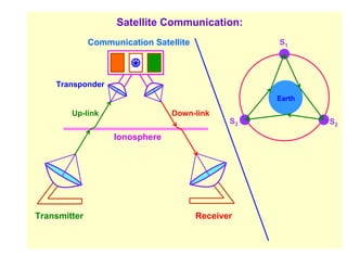
![Satellite communication uses UHF / Microwave regions. Microwaves carrying
audio, video, telephone, telex, FAX signals, etc. are transmitted from the earth
to the satellites orbiting in the space and retransmitted from the satellites to
different parts of the earth (world).
The special devices used for this purpose in satellites are called
‘transponders’.
Satellite communication is mainly done through ‘geostationary satellites’.
Three geostationary satellites placed in equatorial orbits at 120° from one
another can cover practically the whole populated land area of the world.
Frequency modulation is used for both ‘up channel’ and ‘down channel’
transmission. Though FM needs a larger bandwidth, it offers good immunity
from interference and requires less power in the satellite transmitter.
Orbit of Communication Satellite:
For global communication, a satellite should move uniformly round a circular
orbit with a period of 84.4[r / R]3/2 minutes, where r is the radius of the orbit of
the satellite and R is the radius of the earth.
The circular orbit of the communication satellite is specified in terms of:
(i) The orbit radius (ii) The angle of inclination of the orbit’s plane to the Earth’s
equatorial plane (iii) The position of the ascending mode
(iv) The phase angle of the satellite.](https://image.slidesharecdn.com/10mcommunicationsystems-130115201820-phpapp02/85/10m-communication-systems-25-320.jpg)


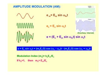
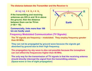
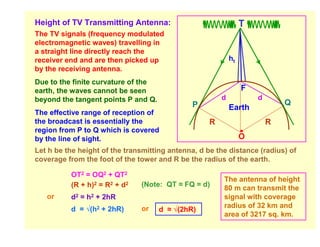
1. The document discusses various types of communication systems including wire links, wireless, and optic fibers. 2. It describes amplitude modulation where the amplitude of a carrier wave is varied in accordance with the modulating signal. 3. For television signals to be transmitted via line-of-sight propagation, the height of transmitting antennas must be sufficient to allow signals to pass the earth's curvature.