Downloaded 180 times

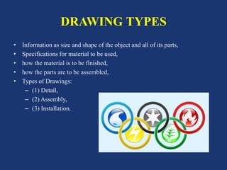


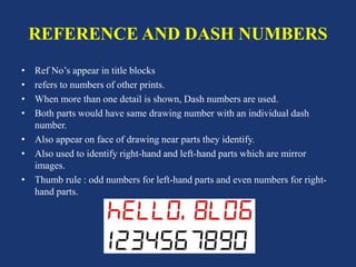
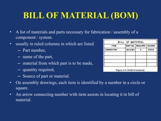
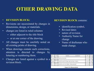


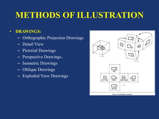
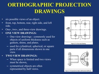

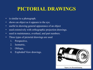
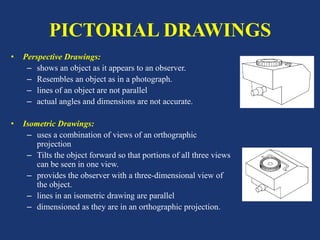


This document provides information about aircraft drawings, including: 1. It describes different types of drawings like detail drawings, assembly drawings, and installation drawings that provide information about individual parts, assembled objects, and part locations. 2. It discusses drafting techniques used in drawings like orthographic projections, sectional views, title blocks, dimensions, tolerances, and pictorial views. 3. It explains various drawing annotations used to identify parts, revisions, materials, and locations on aircraft like reference numbers, zone numbers, station numbers, and butt lines.