Downloaded 294 times

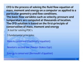
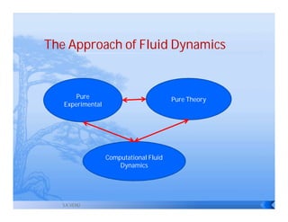


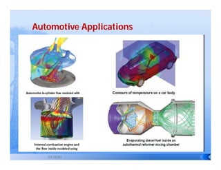


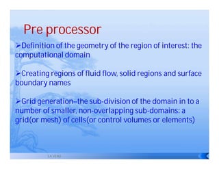

CFD is the process of solving fluid flow equations numerically on a computer to obtain approximations of the flow around complex geometries. It involves dividing the domain into a grid, solving the governing equations at grid points using techniques like finite volume method, and visualizing results using tools like contour plots. CFD complements experimental and theoretical methods by providing a cost-effective way to simulate real flows and gain insights into designs.