Downloaded 26 times
![4-2
Damage to metal aircraft structures is often caused by
corrosion, erosion, normal stress, and accidents and mishaps.
Sometimes aircraft structure modiications require extensive
structural rework. For example, the installation of winglets
on aircraft not only replaces a wing tip with a winglet, but
also requires extensive reinforcing of the wing structure to
carry additional stresses.
Numerous and varied methods of repairing metal structural
portions of an aircraft exist, but no set of speciic repair
patterns applies in all cases. The problem of repairing a
damaged section is usually solved by duplicating the original
part in strength, kind of material, and dimensions. To make a
structural repair, the aircraft technician needs a good working
knowledge of sheet metal forming methods and techniques. In
general, forming means changing the shape by bending and
forming solid metal. In the case of aluminum, this is usually
done at room temperature. All repair parts are shaped to it in
place before they are attached to the aircraft or component.
Forming may be a very simple operation, such as making
a single bend or a single curve, or it may be a complex
operation, requiring a compound curvature. Before forming
a part, the aircraft technician must give some thought to
the complexity of the bends, the material type, the material
thickness, the material temper, and the size of the part being
fabricated. In most cases, these factors determine which
forming method to use. Types of forming discussed in this
chapter include bending, brake forming, stretch forming, roll
forming, and spinning. The aircraft technician also needs
a working knowledge of the proper use of the tools and
equipment used in forming metal.
In addition to forming techniques, this chapter introduces
the airframe technician to the tools used in sheet metal
construction and repair, structural fasteners and their
installation, how to inspect, classify, and assess metal
structural damage, common repair practices, and types of
repairs.
The repairs discussed in this chapter are typical of those used
in aircraft maintenance and are included to introduce some of
the operations involved. For exact information about speciic
repairs, consult the manufacturer’s maintenance or structural
repair manuals (SRM). General repair instructions are also
discussed in Advisory Circular (AC) 43.13.1, Acceptable
Methods, Techniques, and Practices—Aircraft Inspection
and Repair.
Stresses in Structural Members
An aircraft structure must be designed so that it accepts all of
the stresses imposed upon it by the light and ground loads
without any permanent deformation. Any repair made must
accept the stresses, carry them across the repair, and then
transfer them back into the original structure. These stresses
are considered as lowing through the structure, so there
must be a continuous path for them, with no abrupt changes
in cross-sectional areas along the way. Abrupt changes in
cross-sectional areas of aircraft structure that are subject to
cycle loading or stresses result in a stress concentration that
may induce fatigue cracking and eventual failure. A scratch or
gouge in the surface of a highly stressed piece of metal causes
a stress concentration at the point of damage and could lead
to failure of the part. Forces acting on an aircraft, whether it
is on the ground or in light, introduce pulling, pushing, or
twisting forces within the various members of the aircraft
structure. While the aircraft is on the ground, the weight of
the wings, fuselage, engines, and empennage causes forces
to act downward on the wing and stabilizer tips, along the
spars and stringers, and on the bulkheads and formers. These
forces are passed from member to member causing bending,
twisting, pulling, compression, and shearing forces.
As the aircraft takes off, most of the forces in the fuselage
continue to act in the same direction; because of the motion
of the aircraft, they increase in intensity. The forces on the
wingtips and the wing surfaces, however, reverse direction;
instead of being downward forces of weight, they become
upward forces of lift. The forces of lift are exerted irst
against the skin and stringers, then are passed on to the ribs,
and inally are transmitted through the spars to be distributed
through the fuselage. The wings bend upward at their ends
and may lutter slightly during light. This wing bending
cannot be ignored by the manufacturer in the original design
and construction and cannot be ignored during maintenance.
It is surprising how an aircraft structure composed of
structural members and skin rigidly riveted or bolted together,
such as a wing, can bend or act so much like a leaf spring.
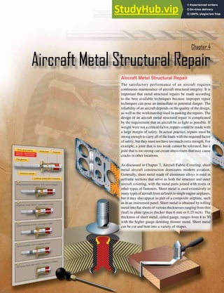
The six types of stress in an aircraft are described as tension,
compression, shear, bearing, bending, and torsion (or
twisting). The irst four are commonly called basic stresses;
the last two, combination stresses. Stresses usually act in
combinations rather than singly. [Figure 4-1]
Tension
Tension is the stress that resists a force that tends to pull apart.
The engine pulls the aircraft forward, but air resistance tries
to hold it back. The result is tension, which tends to stretch
the aircraft. The tensile strength of a material is measured in
pounds per square inch (psi) and is calculated by dividing
the load (in pounds) required to pull the material apart by its
cross-sectional area (in square inches).
The strength of a member in tension is determined on
the basis of its gross area (or total area), but calculations](https://image.slidesharecdn.com/aircraftmetalstructuralrepair-230807175411-df5215b3/85/Aircraft-Metal-Structural-Repair-pdf-2-320.jpg)
![4-3
Figure 4-1. Stresses in aircraft structures.
Compression
Tension
E. Bending
A. Tension
B. Compression
C. Torsion
D. Shear
Figure 4-2. Bearing stress.
Rivets
Top sheet is bearing against
the bottom sheet. Fasteners
are pressing top sheet against
bottom bearing
The force that
tries to pull the
two sheets apart
Bearing
stress
involving tension must take into consideration the net area of
the member. Net area is deined as the gross area minus that
removed by drilling holes or by making other changes in the
section. Placing rivets or bolts in holes makes no appreciable
difference in added strength, as the rivets or bolts will not
transfer tensional loads across holes in which they are inserted.
Compression
Compression, the stress that resists a crushing force, tends to
shorten or squeeze aircraft parts. The compressive strength of
a material is also measured in psi. Under a compressive load,
an undrilled member is stronger than an identical member
with holes drilled through it. However, if a plug of equivalent
or stronger material is itted tightly in a drilled member, it
transfers compressive loads across the hole, and the member
carries approximately as large a load as if the hole were not
there. Thus, for compressive loads, the gross or total area may
be used in determining the stress in a member if all holes are
tightly plugged with equivalent or stronger material.
Shear
Shear is the stress that resists the force tending to cause one
layer of a material to slide over an adjacent layer. Two riveted
plates in tension subject the rivets to a shearing force. Usually,
the shear strength of a material is either equal to or less than
its tensile or compressive strength. Shear stress concerns the
aviation technician chiely from the standpoint of the rivet
and bolt applications, particularly when attaching sheet metal,
because if a rivet used in a shear application gives way, the
riveted or bolted parts are pushed sideways.
Bearing
Bearing stress resists the force that the rivet or bolt places
on the hole. As a rule, the strength of the fastener should be
such that its total shear strength is approximately equal to
the total bearing strength of the sheet material. [Figure 4-2]
Torsion
Torsion is the stress that produces twisting. While moving
the aircraft forward, the engine also tends to twist it to one
side, but other aircraft components hold it on course. Thus,
torsion is created. The torsional strength of a material is its
resistance to twisting or torque (twisting stress). The stresses
arising from this action are shear stresses caused by the
rotation of adjacent planes past each other around a common](https://image.slidesharecdn.com/aircraftmetalstructuralrepair-230807175411-df5215b3/85/Aircraft-Metal-Structural-Repair-pdf-3-320.jpg)
![4-4
Figure 4-3. Scales.
1 2 3 4 5 6 7 8 9
1 2 3 4 6 7 8 9
8 16 24 32 40 48 56
4 8 12 16 20 24 28
28 4
56 8
1
9
1 2 3 4 5 6 7 8 9
4 8 12 16 20 24 28
4 8 12 16 20 24 28 4 8 12 16 20 24 28
8 16 24 32 40 48 56
8 16 24 32 40 48 56 8 16 24 32 40 48 56
1 2 3 4 5 6 7 8 9 1 2 3 4 5 6 7 8 9
1 2 3 4 6 7 8 9
5
1 2 3 4 6 7 8 9
5
1 2 3 4 6 7 8 9
5
9 1
5
10 THS
100 THS
32 MOS
64 THS
3
3
2
1 2 5
5
4
1
1 2 3 4 5
4
8 THS
16 THS
reference axis at right angles to these planes. This action may
be illustrated by a rod ixed solidly at one end and twisted
by a weight placed on a lever arm at the other, producing the
equivalent of two equal and opposite forces acting on the rod
at some distance from each other. A shearing action is set up
all along the rod, with the center line of the rod representing
the neutral axis.
Bending
Bending (or beam stress) is a combination of compression
and tension. The rod in Figure 4-1E has been shortened
(compressed) on the inside of the bend and stretched on
the outside of the bend. Note that the bending stress causes
a tensile stress to act on the upper half of the beam and a
compressive stress on the lower half. These stresses act in
opposition on the two sides of the center line of the member,
which is called the neutral axis. Since these forces acting in
opposite directions are next to each other at the neutral axis,
the greatest shear stress occurs along this line, and none exists
at the extreme upper or lower surfaces of the beam.
Tools for Sheet Metal Construction and
Repair
Without modern metalworking tools and machines, the
job of the airframe technician would be more dificult and
tiresome, and the time required to inish a task would be
much greater. These specialized tools and machines help the
airframe technician construct or repair sheet metal in a faster,
simpler, and better manner than possible in the past. Powered
by human muscle, electricity, or compressed air, these tools
are used to lay out, mark, cut, sand, or drill sheet metal.
Layout Tools
Before itting repair parts into an aircraft structure, the new
sections must be measured and marked, or laid out to the
dimensions needed to make the repair part. Tools utilized
for this process are discussed in this section.
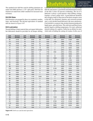
Scales
Scales are available in various lengths, with the 6-inch and
12-inch scales being the most common and affordable. A
scale with fractions on one side and decimals on the other side
is very useful. To obtain an accurate measurement, measure
with the scale held on edge from the 1-inch mark instead of
the end. Use the graduation marks on the side to set a divider
or compass. [Figure 4-3]
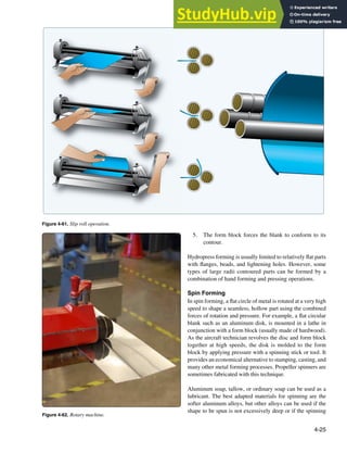
Combination Square
A combination square consists of a steel scale with three
heads that can be moved to any position on the scale and
locked in place. The three heads are a stock head that
measures 90° and 45° angles, a protractor head that can
measure any angle between the head and the blade, and a
center head that uses one side of the blade as the bisector of
a 90° angle. The center of a shaft can be found by using the
center head. Place the end of the shaft in the V of the head
and scribe a line along the edge of the scale. Rotate the head
about 90° and scribe another line along the edge of the scale.
The two lines will cross at the center of the shaft. [Figure 4-4]
Dividers
Dividers are used to transfer a measurement from a device
to a scale to determine its value. Place the sharp points at
the locations from which the measurement is to be taken.
Then, place the points on a steel machinist’s scale, but put
one of the points on the 1-inch mark and measure from there.
[Figure 4-5]
Rivet Spacers
A rivet spacer is used to make a quick and accurate rivet
pattern layout on a sheet. On the rivet spacer, there are
alignment marks for 1
⁄2-inch, 3
⁄4-inch, 1-inch and 2-inch rivet
spacing. [Figure 4-6]
Marking Tools
Pens
Fiber-tipped pens are the preferred method of marking
lines and hole locations directly on aluminum, because the
graphite in a No. 2 pencil can cause corrosion when used on](https://image.slidesharecdn.com/aircraftmetalstructuralrepair-230807175411-df5215b3/85/Aircraft-Metal-Structural-Repair-pdf-4-320.jpg)
![4-5
Figure 4-4. Combination square.
11
2
0
180
90
3 4 5 8 9 10
Scriber
Level
Stock head Protractor head Center head
Figure 4-5. Divider.
Figure 4-6. Rivet spacer.
Figure 4-7. Scribe.
aluminum. Make the layout on the protective membrane if it
is still on the material, or mark directly on the material with
a iber-tipped pen, such as a ine-point Sharpie®, or cover
the material with masking tape and then mark on the tape.
Scribes
A scribe is a pointed instrument used to mark or score metal
to show where it is to be cut. A scribe should only be used
when marks will be removed by drilling or cutting because
it makes scratches that weaken the material and could cause
corrosion. [Figure 4-7]
Punches
Punches are usually made of carbon steel that has been
hardened and tempered. Generally classiied as solid or
hollow, punches are designed according to their intended
use. A solid punch is a steel rod with various shapes at the
end for different uses. For example, it is used to drive bolts
out of holes, loosen frozen or tight pins and keys, knock out
rivets, pierce holes in a material, etc. The hollow punch is
sharp edged and used most often for cutting out blanks. Solid
punches vary in both size and point design, while hollow
punches vary in size.](https://image.slidesharecdn.com/aircraftmetalstructuralrepair-230807175411-df5215b3/85/Aircraft-Metal-Structural-Repair-pdf-5-320.jpg)
![4-6
Figure 4-8. Prick punch.
Figure 4-9. Center punch.
Figure 4-10. Automatic center punch.
Figure 4-11. Transfer punch.
Transfer punch
Use old skin as template
New skin
Prick Punch
A prick punch is primarily used during layout to place
reference marks on metal because it produces a small
indentation. [Figure 4-8] After layout is finished, the
indentation is enlarged with a center punch to allow for
drilling. The prick punch can also be used to transfer
dimensions from a paper pattern directly onto the metal.
Take the following precautions when using a prick punch:
• Never strike a prick punch a heavy blow with a
hammer because it could bend the punch or cause
excessive damage to the item being worked.
• Do not use a prick punch to remove objects from holes
because the point of the punch spreads the object and
causes it to bind even more.
Center Punch
A center punch is used to make indentations in metal as an
aid in drilling. [Figure 4-9] These indentations help the drill,
which has a tendency to wander on a lat surface, stay on
the mark as it goes through the metal. The traditional center
punch is used with a hammer, has a heavier body than the
prick punch, and has a point ground to an angle of about 60°.
Take the following precautions when using a center punch:
• Never strike the center punch with enough force to
dimple the item around the indentation or cause the
metal to protrude through the other side of the sheet.
• Do not use a center punch to remove objects from holes
because the point of the punch spreads the object and
causes it to bind even more.
Automatic Center Punch
The automatic center punch performs the same function as an
ordinary center punch, but uses a spring tension mechanism
to create a force hard enough to make an indentation without
the need for a hammer. The mechanism automatically strikes
a blow of the required force when placed where needed and
pressed. This punch has an adjustable cap for regulating
the stroke; the point can be removed for replacement or
sharpening. Never strike an automatic center punch with a
hammer. [Figure 4-10]
Transfer Punch
A transfer punch uses a template or existing holes in the
structure to mark the locations of new holes. The punch is
centered in the old hole over the new sheet and lightly tapped
with a mallet. The result should be a mark that serves to locate
the hole in the new sheet. [Figure 4-11]
Drive Punch
The drive punch is made with a lat face instead of a point
because it is used to drive out damaged rivets, pins, and
bolts that sometimes bind in holes. The size of the punch
is determined by the width of the face, usually 1
⁄8-inch to
1
⁄4-inch. [Figure 4-12]](https://image.slidesharecdn.com/aircraftmetalstructuralrepair-230807175411-df5215b3/85/Aircraft-Metal-Structural-Repair-pdf-6-320.jpg)
![4-7
Figure 4-13. Pin punch.
Figure 4-12. Drive punch.
Figure 4-14. Chassis punch.
Figure 4-15. Awl.
Figure 4-16. Awl usage.
4
5
6
1
2
3
7
8
9
1
0
1
1
1
2
Pin Punch
The pin punch typically has a straight shank characterized
by a hexagonal body. Pin punch points are sized in 1
⁄32-inch
increments of an inch and range from 1
⁄16-inch to 3
⁄8-inch in
diameter. The usual method for driving out a pin or bolt is
to start working it out with a drive punch until the shank of
the punch is touching the sides of the hole. Then use a pin
punch to drive the pin or bolt the rest of the way out of the
hole. [Figure 4-13]
Chassis Punch
A chassis punch is used to make holes in sheet metal parts for
the installation of instruments and other avionics appliance,
as well as lightening holes in ribs and spars. Sized in 1
⁄16 of
an inch, they are available in sizes from 1
⁄2 inch to 3 inches.
[Figure 4-14]
Awl
A pointed tool for marking surfaces or for punching small
holes, an awl is used in aircraft maintenance to place scribe
marks on metal and plastic surfaces and to align holes, such
as in the installation of a deicer boot. [Figure 4-15]
Procedures for one use of an awl:
1. Place the metal to be scribed on a lat surface. Place
a ruler or straightedge on the guide marks already
measured and placed on the metal.
2. Remove the protective cover from the awl.
3. Hold the straightedge irmly. Hold the awl, as shown
in Figure 4-16, and scribe a line along the straightedge.
4. Replace the protective cover on the awl.](https://image.slidesharecdn.com/aircraftmetalstructuralrepair-230807175411-df5215b3/85/Aircraft-Metal-Structural-Repair-pdf-7-320.jpg)
![4-8
Figure 4-17. Hole duplicator.
New skin
Old skin
Angle
Figure 4-18. Kett saw.
Figure 4-19. Pneumatic circular saw.
Hole Duplicator
Available in a variety of sizes and styles, hole duplicators,
or hole inders, utilize the old covering as a template to
locate and match existing holes in the structure. Holes in
a replacement sheet or in a patch must be drilled to match
existing holes in the structure and the hole duplicator
simpliies this process. Figure 4-17 illustrates one type of
hole duplicator. The peg on the bottom leg of the duplicator
its into the existing rivet hole. To make the hole in the
replacement sheet or patch, drill through the bushing on the
top leg. If the duplicator is properly made, holes drilled in
this manner are in perfect alignment. A separate duplicator
must be used for each diameter of rivet.
Cutting Tools
Powered and nonpowered metal cutting tools available to the
aviation technician include various types of saws, nibblers,
shears, sanders, notchers, and grinders.
Circular-Cutting Saws
The circular cutting saw cuts with a toothed, steel disk that
rotates at high speed. Handheld or table mounted and powered
by compressed air, this power saw cuts metal or wood. To
prevent the saw from grabbing the metal, keep a irm grip
on the saw handle at all times. Check the blade carefully for
cracks prior to installation because a cracked blade can ly
apart during use, possibly causing serious injury.
Kett Saw
The Kett saw is an electrically operated, portable circular
cuttingsawthatusesbladesofvariousdiameters.[Figure4-18]
Since the head of this saw can be turned to any desired angle,
it is useful for removing damaged sections on a stringer. The
advantages of a Kett saw include:
1. Can cut metal up to 3
⁄16-inch in thickness.
2. No starting hole is required.
3. A cut can be started anywhere on a sheet of metal.
4. Can cut an inside or outside radius.
Pneumatic Circular Cutting Saw
The pneumatic circular cutting saw, useful for cutting out
damage, is similar to the Kett saw. [Figure 4-19]](https://image.slidesharecdn.com/aircraftmetalstructuralrepair-230807175411-df5215b3/85/Aircraft-Metal-Structural-Repair-pdf-8-320.jpg)
![4-9
Figure 4-20. Reciprocating saw.
Figure 4-21. Die grinder and cut-off wheel.
Figure 4-22. Nibbler.
Figure 4-23. Power squaring shear.
Nibblers
Usually powered by compressed air, the nibbler is another
tool for cutting sheet metal. Portable nibblers utilize a high
speed blanking action (the lower die moves up and down and
meets the upper stationary die) to cut the metal. [Figure 4-22]
The shape of the lower die cuts out small pieces of metal
approximately 1
⁄16 inch wide.
The cutting speed of the nibbler is controlled by the thickness
of the metal being cut. Nibblers satisfactorily cut through
sheets of metal with a maximum thickness of 1
⁄16 inch. Too
much force applied to the metal during the cutting operation
clogs the dies (shaped metal), causing them to fail or the motor
to overheat. Both electric and hand nibblers are available.
Shop Tools
Due to size, weight, and/or power source, shop tools are
usually in a ixed location, and the airframe part to be
constructed or repaired is brought to the tool.
Squaring Shear
The squaring shear provides the airframe technician with
a convenient means of cutting and squaring sheet metal.
Available as a manual, hydraulic, or pneumatic model,
this shear consists of a stationary lower blade attached to
a bed and a movable upper blade attached to a crosshead.
[Figure 4-23]
Reciprocating Saw
The versatile reciprocating saw achieves cutting action
through a push and pull (reciprocating) motion of the blade.
This saw can be used right sideup or upside down, a feature
that makes it handier than the circular saw for working in tight
or awkward spots. A variety of blade types are available for
reciprocating saws; blades with iner teeth are used for cutting
through metal. The portable, air-powered reciprocating saw
uses a standard hacksaw blade and can cut a 360° circle or
a square or rectangular hole. Unsuited for ine precision
work, this saw is more dificult to control than the pneumatic
circular cutting saw. A reciprocating saw should be used in
such a way that at least two teeth of the saw blade are cutting
at all times. Avoid applying too much downward pressure on
the saw handle because the blade may break. [Figure 4-20]
Cut-off Wheel
A cut-off wheel is a thin abrasive disc driven by a high-speed
pneumatic die-grinder and used to cut out damage on aircraft
skin and stringers. The wheels come in different thicknesses
and sizes. [Figure 4-21]](https://image.slidesharecdn.com/aircraftmetalstructuralrepair-230807175411-df5215b3/85/Aircraft-Metal-Structural-Repair-pdf-9-320.jpg)
![4-10
Figure 4-24. Foot-operated squaring shear.
Figure 4-25. Throatless shears.
A hand lever operates the cutting blade which is the top blade.
Throatless shears made by the Beverly Shear Manufacturing
Corporation, called BeverlyTM shears, are often used.
Scroll Shears
Scroll shears are used for cutting irregular lines on the
inside of a sheet without cutting through to the edge.
[Figure 4-26] The upper cutting blade is stationary while
the lower blade is movable. A handle connected to the lower
blade operates the machine.
Rotary Punch Press
Used in the airframe repair shop to punch holes in metal
parts, the rotary punch can cut radii in corners, make washers,
and perform many other jobs where holes are required.
[Figure 4-27] The machine is composed of two cylindrical
turrets, one mounted over the other and supported by the
frame, with both turrets synchronized to rotate together.
Index pins, which ensure correct alignment at all times, may
be released from their locking position by rotating a lever
on the right side of the machine. This action withdraws the
index pins from the tapered holes and allows an operator to
turn the turrets to any size punch desired.
Two squaring fences, consisting of thick strips of metal used
for squaring metal sheets, are placed on the bed. One squaring
fence is placed on the right side and one on the left to form a
90° angle with the blades. A scale graduated in fractions of
an inch is scribed on the bed for ease in placement.
To make a cut with a foot shear, move the upper blade down
by placing the foot on the treadle and pushing downward.
Once the metal is cut and foot pressure removed, a spring
raises the blade and treadle. Hydraulic or pneumatic models
utilize remote foot pedals to ensure operator safety.
The squaring shear performs three distinctly different
operations:
1. Cutting to a line
2. Squaring
3. Multiple cutting to a speciic size
When cutting to a line, place the sheet on the bed of the shears
in front of the cutting blade with the cutting line even with
the cutting edge of the bed. To cut the sheet with a foot shear,
step on the treadle while holding the sheet securely in place.
Squaring requires several steps. First, one end of the sheet
is squared with an edge (the squaring fence is usually used
on the edge). Then, the remaining edges are squared by
holding one squared end of the sheet against the squaring
fence and making the cut, one edge at a time, until all edges
have been squared.
When several pieces must be cut to the same dimensions, use
the backstop, located on the back of the cutting edge on most
squaring shears. The supporting rods are graduated in fractions
of an inch and the gauge bar may be set at any point on the rods.
Set the gauge bar the desired distance from the cutting blade
of the shears and push each piece to be cut against the gauge
bar. All the pieces can then be cut to the same dimensions
without measuring and marking each one separately.
Foot-operated shears have a maximum metal cutting capacity
of 0.063 inch of aluminum alloy. Use powered squaring
shears for cutting thicker metals. [Figure 4-24]
Throatless Shear
Airframe technicians use the throatless shear to cut aluminum
sheets up to 0.063 inches. This shear takes its name from the
fact that metal can be freely moved around the cutting blade
during cutting because the shear lacks a “throat” down which
metal must be fed. [Figure 4-25] This feature allows great
lexibility in what shapes can be cut because the metal can
be turned to any angle for straight, curved, and irregular cuts.
Also, a sheet of any length can be cut.](https://image.slidesharecdn.com/aircraftmetalstructuralrepair-230807175411-df5215b3/85/Aircraft-Metal-Structural-Repair-pdf-10-320.jpg)
![4-11
Figure 4-26. Scroll shears.
Figure 4-27. Rotary punch press.
Figure 4-29. Combination disk and belt sander.
Figure 4-28. Band saw.
When rotating the turret to change punches, release the
index lever when the desired die is within 1 inch of the ram,
and continue to rotate the turret slowly until the top of the
punch holder slides into the grooved end of the ram. The
tapered index locking pins will then seat themselves in the
holes provided and, at the same time, release the mechanical
locking device, which prevents punching until the turrets
are aligned.
To operate the machine, place the metal to be worked between
the die and punch. Pull the lever on the top of the machine
toward the operator, actuating the pinion shaft, gear segment,
toggle link, and the ram, forcing the punch through the metal.
When the lever is returned to its original position, the metal
is removed from the punch.
The diameter of the punch is stamped on the front of each
die holder. Each punch has a point in its center that is
placed in the center punch mark to punch the hole in the
correct location.
Band Saw
A band saw consists of a toothed metal band coupled to,
and continuously driven around, the circumferences of two
wheels. It is used to cut aluminum, steel, and composite parts.
[Figure 4-28] The speed of the band saw and the type and
style of the blade depends on the material to be cut. Band
saws are often designated to cut one type of material, and
if a different material is to be cut, the blade is changed. The
speed is controllable and the cutting platform can be tilted
to cut angled pieces.
Disk Sander
Disk sanders have a powered abrasive-covered disk or belt
and are used for smoothing or polishing surfaces. The sander
unit uses abrasive paper of different grits to trim metal parts.
It is much quicker to use a disk sander than to ile a part to
the correct dimension. The combination disk and belt sander
has a vertical belt sander coupled with a disk sander and is
often used in a metal shop. [Figure 4-29]
Belt Sander
The belt sander uses an endless abrasive belt driven by an
electric motor to sand down metal parts much like the disk
sander unit. The abrasive paper used on the belt comes in
different degrees of grit or coarseness. The belt sander is](https://image.slidesharecdn.com/aircraftmetalstructuralrepair-230807175411-df5215b3/85/Aircraft-Metal-Structural-Repair-pdf-11-320.jpg)
![4-12
Figure 4-31. Notcher.
Figure 4-32. Power notcher.
Figure 4-33. Grinder.
Tool rest
Figure 4-30. Belt sander.
available as a vertical or horizontal unit. The tension and
tracking of the abrasive belt can be adjusted so the belt runs
in the middle. [Figure 4-30]
Notcher
The notcher is used to cut out metal parts, with some
machines capable of shearing, squaring, and trimming
metal. [Figure 4-31] The notcher consists of a top and
bottom die and most often cuts at a 90° angle, although some
machines can cut metal into angles up to 180°. Notchers
are available in manual and pneumatic models able to cut
various thicknesses of mild steel and aluminum. This is an
excellent tool for quickly removing corners from sheet metal
parts. [Figure 4-32]
Wet or Dry Grinder
Grinding machines come in a variety of types and sizes,
depending upon the class of work for which they are to be
used. Dry and/or wet grinders are found in airframe repair
shops. Grinders can be bench or pedestal mounted. A dry
grinder usually has a grinding wheel on each end of a shaft
that runs through an electric motor or a pulley operated by a
belt. The wet grinder has a pump to supply a low of water
on a single grinding wheel. The water acts as a lubricant for
faster grinding while it continuously cools the edge of the
metal, reducing the heat produced by material being ground
against the wheel. It also washes away any bits of metal or
abrasive removed during the grinding operation. The water
returns to a tank and can be re-used.
Grinders are used to sharpen knives, tools, and blades as
well as grinding steel, metal objects, drill bits, and tools.
Figure 4-33 illustrates a common type bench grinder
found in most airframe repair shops. It can be used to
dress mushroomed heads on chisels and points on chisels,
screwdrivers, and drills, as well as for removing excess metal
from work and smoothing metal surfaces.](https://image.slidesharecdn.com/aircraftmetalstructuralrepair-230807175411-df5215b3/85/Aircraft-Metal-Structural-Repair-pdf-12-320.jpg)
![4-13
Figure 4-34. Straight snips.
Figure 4-35. Aviation snips.
The bench grinder is generally equipped with one medium-
grit and one ine-grit abrasive wheel. The medium-grit wheel
is usually used for rough grinding where a considerable
quantity of material is to be removed or where a smooth inish
is unimportant. The ine-grit wheel is used for sharpening
tools and grinding to close limits. It removes metal more
slowly, gives the work a smooth inish, and does not generate
enough heat to anneal the edges of cutting tools.
Before using any type of grinder, ensure that the abrasive
wheels are irmly held on the spindles by the lange nuts.
An abrasive wheel that comes off or becomes loose could
seriously injure the operator in addition to ruining the grinder.
A loose tool rest could cause the tool or piece of work to be
“grabbed” by the abrasive wheel and cause the operator’s
hand to come in contact with the wheel, possibly resulting
in severe wounds.
Always wear goggles when using a grinder, even if eyeshields
are attached to the grinder. Goggles should it irmly against
the face and nose. This is the only way to protect the eyes
from the ine pieces of steel. Goggles that do not it properly
should be exchanged for ones that do it. Be sure to check
the abrasive wheel for cracks before using the grinder. A
cracked abrasive wheel is likely to ly apart when turning at
high speeds. Never use a grinder unless it is equipped with
wheel guards that are irmly in place.
Grinding Wheels
A grinding wheel is made of a bonded abrasive and provides
an eficient way to cut, shape, and inish metals. Available in
a wide variety of sizes and numerous shapes, grinding wheels
are also used to sharpen knives, drill bits, and many other
tools, or to clean and prepare surfaces for painting or plating.
Grinding wheels are removable and a polishing or bufing
wheel can be substituted for the abrasive wheel. Silicon
carbide and aluminum oxide are the kinds of abrasives used
in most grinding wheels. Silicon carbide is the cutting agent
for grinding hard, brittle material, such as cast iron. It is
also used in grinding aluminum, brass, bronze, and copper.
Aluminum oxide is the cutting agent for grinding steel and
other metals of high tensile strength.
Hand Cutting Tools
Many types of hand cutting tools are available to cut light
gauge sheet metal. Four cutting tools commonly found in the
air frame repair shop are straight hand snips, aviation snips,
iles, and burring tools.
Straight Snips
Straight snips, or sheet metal shears, have straight
blades with cutting edges sharpened to an 85° angle.
[Figure 4-34] Available in sizes ranging from 6 to 14 inches,
they cut aluminum up to 1
⁄16 of an inch. Straight snips can be
used for straight cutting and large curves, but aviation snips
are better for cutting circles or arcs.
Aviation Snips
Aviation snips are used to cut holes, curved parts, round
patches, and doublers (a piece of metal placed under a part
to make it stiffer) in sheet metal. Aviation snips have colored
handles to identify the direction of the cuts: yellow aviation
snips cut straight, green aviation snips curve right, and red
aviation snips curve left. [Figure 4-35]
Files
The ile is an important but often overlooked tool used to
shape metal by cutting and abrasion. Files have ive distinct
properties: length, contour, the form in cross section, the
kind of teeth, and the ineness of the teeth. Many different
types of iles are available and the sizes range from 3 to 18
inches. [Figure 4-36]](https://image.slidesharecdn.com/aircraftmetalstructuralrepair-230807175411-df5215b3/85/Aircraft-Metal-Structural-Repair-pdf-13-320.jpg)
![4-14
Figure 4-37. Die grinder.
Figure 4-38. Burring tools.
Figure 4-36. Files.
The portion of the ile on which the teeth are cut is called the
face. The tapered end that its into the handle is called the tang.
The part of the ile where the tang begins is the heel. The length
of a ile is the distance from the point or tip to the heel and
does not include the tang. The teeth of the ile do the cutting.
These teeth are set at an angle across the face of the ile. A
ile with a single row of parallel teeth is called a single-cut
ile. The teeth are cut at an angle of 65°–85° to the centerline,
depending on the intended use of the ile. Files that have one
row of teeth crossing another row in a crisscross pattern are
called double-cut iles. The angle of the irst set usually is
40°–50° and that of the crossing teeth 70°–80°. Crisscrossing
produces a surface that has a very large number of little teeth
that slant toward the tip of the ile. Each little tooth looks like
an end of a diamond point cold chisel.
Files are graded according to the tooth spacing; a coarse ile
has a small number of large teeth, and a smooth ile has a large
number of ine teeth. The coarser the teeth, the more metal is
removed on each stroke of the ile. The terms used to indicate
the coarseness or ineness of a ile are rough, coarse, bastard,
second cut, smooth, and dead smooth, and the ile may be
either single cut or double cut. Files are further classiied
according to their shape. Some of the more common types
are: lat, triangle, square, half round, and round.
There are several iling techniques. The most common is to
remove rough edges and slivers from the inished part before
it is installed. Crossiling is a method used for iling the
edges of metal parts that must it tightly together. Crossiling
involves clamping the metal between two strips of wood
and iling the edge of the metal down to a preset line. Draw
iling is used when larger surfaces need to be smoothed and
squared. It is done by drawing the ile over the entire surface
of the work.
To protect the teeth of a ile, iles should be stored separately
in a plastic wrap or hung by their handles. Files kept in a
toolbox should be wrapped in waxed paper to prevent rust
from forming on the teeth. File teeth can be cleaned with a
ile card.
Die Grinder
A die grinder is a handheld tool that turns a mounted
cutoff wheel, rotary ile, or sanding disk at high speed.
[Figure 4-37] Usually powered by compressed air, electric
die grinders are also used. Pneumatic die grinders run at
12,000 to 20,000 revolutions per minute (rpm) with the
rotational speed controlled by the operator who uses a hand-
or foot-operated throttle to vary the volume of compressed
air. Available in straight, 45°, and 90° models, the die
grinder is excellent for weld breaking, smoothing sharp
edges, deburring, porting, and general high-speed polishing,
grinding, and cutting.
Burring Tool
This type of tool is used to remove a burr from an edge of a
sheet or to deburr a hole. [Figure 4-38]
Hole Drilling
Drilling holes is a common operation in the airframe repair
shop. Once the fundamentals of drills and their uses are
learned, drilling holes for rivets and bolts on light metal is
not dificult. While a small portable power drill is usually
the most practical tool for this common operation in airframe
metalwork, sometimes a drill press may prove to be the better
piece of equipment for the job.](https://image.slidesharecdn.com/aircraftmetalstructuralrepair-230807175411-df5215b3/85/Aircraft-Metal-Structural-Repair-pdf-14-320.jpg)
![4-15
Figure 4-39. Drill motors.
Figure 4-41. Nutplate drill.
Figure 4-40. Angle drill motors.
Portable Power Drills
Portable power drills operate by electricity or compressed air.
Pneumatic drill motors are recommended for use on repairs
around lammable materials where potential sparks from an
electric drill motor might become a ire hazard.
When using the portable power drill, hold it irmly with both
hands. Before drilling, be sure to place a backup block of
wood under the hole to be drilled to add support to the metal
structure. The drill bit should be inserted in the chuck and
tested for trueness or vibration. This may be visibly checked
by running the motor freely. A drill bit that wobbles or is
slightly bent should not be used since such a condition causes
enlarged holes. The drill should always be held at right angles
to the work regardless of the position or curvatures. Tilting
the drill at any time when drilling into or withdrawing from
the material may cause elongation (egg shape) of the hole.
When drilling through sheet metal, small burrs are formed
around the edge of the hole. Burrs must be removed to allow
rivets or bolts to it snugly and to prevent scratching. Burrs
may be removed with a bearing scraper, a countersink, or
a drill bit larger than the hole. If a drill bit or countersink
is used, it should be rotated by hand. Always wear safety
goggles while drilling.
Pneumatic Drill Motors
Pneumatic drill motors are the most common type of drill
motor for aircraft repair work. [Figure 4-39] They are light
weight and have suficient power and good speed control.
Drill motors are available in many different sizes and models.
Most drill motors used for aircraft sheet metal work are rated
at 3,000 rpm, but if drilling deep holes or drilling in hard
materials, such as corrosion resistant steel or titanium, a drill
motor with more torque and lower rpm should be selected to
prevent damage to tools and materials.
Right Angle and 45° Drill Motors
Right angle and 45° drill motors are used for positions that are
not accessible with a pistol grip drill motor. Most right angle
drill motors use threaded drill bits that are available in several
lengths. Heavy-duty right angle drills are equipped with a
chuck similar to the pistol grip drill motor. [Figure 4-40]
Two Hole
Special drill motors that drill two holes at the same time are
used for the installation of nutplates. By drilling two holes
at the same time, the distance between the holes is ixed and
the holes line up perfectly with the holes in the nutplate.
[Figure 4-41]
Drill Press
The drill press is a precision machine used for drilling holes
that require a high degree of accuracy. It serves as an accurate
means of locating and maintaining the direction of a hole that
is to be drilled and provides the operator with a feed lever
that makes the task of feeding the drill into the work easier.
The upright drill press is the most common of the variety of
drill presses available. [Figure 4-42]](https://image.slidesharecdn.com/aircraftmetalstructuralrepair-230807175411-df5215b3/85/Aircraft-Metal-Structural-Repair-pdf-15-320.jpg)
![4-16
Figure 4-42. Drill press.
When using a drill press, the height of the drill press table is
adjusted to accommodate the height of the part to be drilled.
When the height of the part is greater than the distance
between the drill and the table, the table is lowered. When
the height of the part is less than the distance between the
drill and the table, the table is raised.
After the table is properly adjusted, the part is placed on the
table and the drill is brought down to aid in positioning the
metal so that the hole to be drilled is directly beneath the point
of the drill. The part is then clamped to the drill press table to
prevent it from slipping during the drilling operation. Parts
not properly clamped may bind on the drill and start spinning,
causing serious cuts on the operator’s arms or body, or loss
of ingers or hands. Always make sure the part to be drilled
is properly clamped to the drill press table before starting
the drilling operation.
The degree of accuracy that it is possible to attain when using
the drill press depends to a certain extent on the condition of
the spindle hole, sleeves, and drill shank. Therefore, special
care must be exercised to keep these parts clean and free from
nicks, dents, and warpage. Always be sure that the sleeve is
securely pressed into the spindle hole. Never insert a broken
drill in a sleeve or spindle hole. Be careful never to use the
sleeve-clamping vise to remove a drill since this may cause
the sleeve to warp.
The drill speed on a drill press is adjustable. Always select the
optimum drill speed for the material to be drilled. Technically,
the speed of a drill bit means its speed at the circumference,
in surface feet per minute (sfm). The recommended speed for
drilling aluminum alloy is from 200 to 300 sfm, and for mild
steel is 30 to 50 sfm. In practice, this must be converted into
rpm for each size drill. Machinist and mechanic handbooks
include drill rpm charts or drill rpm may be computed by
use of the formula:
CS × 4
= rpm
D
CS = The recommended cutting speed in sfm
D = The diameter of the drill bit in inches
Example: At what rpm should a 1
⁄8-inch drill turn to drill
aluminum at 300 sfm?
Drill Extensions and Adapters
When access to a place where drilling is difficult or
impossible with a straight drill motor, various types of drill
extensions and adapters are used.
Extension Drill Bits
Extension drill bits are widely used for drilling holes in
locations that require reaching through small openings or
past projections. These drill bits, which come in 6- to 12-
inch lengths, are high speed with spring-tempered shanks.
Extension drill bits are ground to a special notched point,
which reduces end thrust to a minimum. When using
extension drill bits always:
1. Select the shortest drill bit that will do the job. It is
easier to control.
2. Check the drill bit for straightness. A bent drill bit
makes an oversized hole and may whip, making it
dificult to control.
3. Keep the drill bit under control. Extension drills
smaller than 1
⁄4-inch must be supported by a drill
guard made from a piece of tubing or spring to prevent
whipping.
Straight Extension
A straight extension for a drill can be made from an ordinary
piece of drill rod. The drill bit is attached to the drill rod by
shrink itting, brazing, or silver soldering.
Angle Adapters
Angle adapters can be attached to an electric or pneumatic
drill when the location of the hole is inaccessible to a straight
drill. Angle adapters have an extended shank fastened to
the chuck of the drill. The drill is held in one hand and the
adapter in the other to prevent the adapter from spinning
around the drill chuck.
Snake Attachment
The snake attachment is a lexible extension used for drilling
in places inaccessible to ordinary drills. Available for electric
and pneumatic drill motors, its lexibility permits drilling
around obstructions with minimum effort. [Figure 4-43]](https://image.slidesharecdn.com/aircraftmetalstructuralrepair-230807175411-df5215b3/85/Aircraft-Metal-Structural-Repair-pdf-16-320.jpg)
![4-17
Figure 4-43. Snake attachment.
Figure 4-44. Parts of a drill.
Figure 4-45. Types of drill bits.
Notched point chisel edge
Flute Cutting lips
Land
Body
Shank
HSS
HSS
HSS
HSS
HSS
HSS
HSS
HSS
HSS
HSS
HSS
HSS
HSS
HSS
HSS
HSS
HSS
HSS
HSS
HSS
HSS
HSS
v
v
v
v
v
/
/
/
/
/
/
/
/
High speed steel, short shank
High speed steel, standard length (jobbers length)
Step drill
Cobalt vanadium alloy, standard length
Figure 4-46. Twist drill bits.
Types of Drill Bits
A wide variety of drill bits including specialty bits for speciic
jobs are available. Figure 4-44 illustrates the parts of the
drill bit and Figure 4-45 shows some commonly used drill
bits. High speed steel (HSS) drill bits come in short shank or
standard length, sometimes called jobbers length. HSS drill
bits can withstand temperatures nearing the critical range of
1,400 °F (dark cherry red) without losing their hardness. The
industry standard for drilling metal (aluminum, steel, etc.),
these drill bits stay sharper longer.
Step Drill Bits
Typically, the procedure for drilling holes larger than 3
⁄16
inch in sheet metal is to drill a pilot hole with a No. 40 or
No. 30 drill bit and then to oversize with a larger drill bit to
the correct size. The step drill combines these two functions
into one step. The step drill bit consists of a smaller pilot
drill point that drills the initial small hole. When the drill bit
is advanced further into the material, the second step of the
drill bit enlarges the hole to the desired size.
Step drill bits are designed to drill round holes in most metals,
plastic, and wood. Commonly used in general construction
and plumbing, they work best on softer materials, such as
plywood, but can be used on very thin sheet metal. Step drill
bits can also be used to deburr holes left by other bits.
Cobalt Alloy Drill Bits
Cobalt alloy drill bits are designed for hard, tough metals like
corrosion-resistant steel and titanium. It is important for the
aircraft technician to note the difference between HSS and
cobalt, because HSS drill bits wear out quickly when drilling
titanium or stainless. Cobalt drill bits are excellent for drilling
titanium or stainless steel, but do not produce a quality hole
in aluminum alloys. Cobalt drill bits can be recognized by
thicker webs and a taper at the end of the drill shank.
Twist Drill Bits
Easily the most popular drill bit type, the twist drill bit has
spiral grooves or lutes running along its working length.
[Figure 4-46] This drill bit comes in a single-luted, two-
luted, three-luted, and four-luted styles. Single-luted and
two-luted drill bits (most commonly available) are used for
originating holes. Three-luted and four-luted drill bits are
used interchangeably to enlarge existing holes. Twist drill
bits are available in a wide choice of tooling materials and
lengths with the variations targeting speciic projects.](https://image.slidesharecdn.com/aircraftmetalstructuralrepair-230807175411-df5215b3/85/Aircraft-Metal-Structural-Repair-pdf-17-320.jpg)
![4-19
Figure 4-48. Reamers.
1
2
3
Figure 4-49. Drill stop.
HSS
HSS
HSS
HSS
HSS
HSS
HSS
HSS
SS
Figure 4-50. Drill bushings.
Arm-type bushing holder
Bushing holder
Figure 4-51. Bushing holder.
deep drilling, the drill should be withdrawn at intervals to
relieve chip packing and to ensure the lubricant reaches the
point. As a general rule, if the drill is large or the material
hard, use a lubricant.
Reamers
Reamers, used for enlarging holes and inishing them smooth
to a required size, are made in many styles. They can be
straight or tapered, solid or expansive, and come with straight
or helical lutes. Figure 4-48 illustrates three types of reamers:
1. Three or four luted production bullet reamers are
customarily used where a iner inish and/or size is
needed than can be achieved with a standard drill bit.
2. Standard or straight reamer.
3. Piloted reamer, with the end reduced to provide
accurate alignment.
The cylindrical parts of most straight reamers are not cutting
edges, but merely grooves cut for the full length of the reamer
body. These grooves provide a way for chips to escape and
a channel for lubricant to reach the cutting edge. Actual
cutting is done on the end of the reamer. The cutting edges
are normally ground to a bevel of 45° ± 5°.
Reamer lutes are not designed to remove chips like a drill.
Do not attempt to withdraw a reamer by turning it in the
reverse direction because chips can be forced into the surface,
scarring the hole.
Drill Stops
A spring drill stop is a wise investment. [Figure 4-49]
Properly adjusted, it can prevent excessive drill penetration
that might damage underlying structure or injure personnel
and prevent the drill chuck from marring the surface. Drill
stops can be made from tubing, iber rod, or hard rubber.
Drill Bushings and Guides
There are several types of tools available that aid in holding
the drill perpendicular to the part. They consist of a hardened
bushing anchored in a holder. [Figure 4-50]
Drill bushing types:
1. Tube—hand-held in an existing hole
2. Commercial—twist lock
3. Commercial—threaded
Drill Bushing Holder Types
There are four types of drill bushing holder:
1. Standard—ine for drilling lat stock or tubing/rod;
uses insert-type bushings.
2. Egg cup—improvement on standard tripod base;
allows drilling on both flat and curved material;
interchangeable bushings allows flexibility.
[Figure 4-51]
3. Plate—used primarily for interchangeable production
components; uses commercial bushings and self-
feeding drills.](https://image.slidesharecdn.com/aircraftmetalstructuralrepair-230807175411-df5215b3/85/Aircraft-Metal-Structural-Repair-pdf-19-320.jpg)
![4-20
Figure 4-53. Drilling large holes.
Figure 4-52. Drilled sheet metal.
4. Arm—used when drilling critical structure;
can be locked in position; uses interchangeable
commercial bushings.
Hole Drilling Techniques
Precise location of drilled holes is sometimes required.
When locating holes to close tolerances, accurately located
punch marks need to be made. If a punch mark is too small,
the chisel edge of the drill bit may bridge it and “walk off”
the exact location before starting. If the punch mark is too
heavy, it may deform the metal and/or result in a local strain
hardening where the drill bit is to start cutting. The best size
for a punch mark is about the width of the chisel edge of the
drill bit to be used. This holds the drill point in place while
starting. The procedure that ensures accurate holes follows:
[Figure 4-52]
1. Measure and lay out the drill locations carefully and
mark with crossed lines.
NOTE: The chisel edge is the least eficient operating
surface element of the twist drill bit because it does
not cut, but actually squeezes or extrudes the work
material.
2. Use a sharp prick punch or spring-loaded center punch
and magnifying glass to further mark the holes.
3. Seat a properly ground center punch (120°–135°) in
the prick punch mark and, holding the center punch
perpendicular to the surface, strike a irm square blow
with a hammer.
4. Mark each hole with a small drill bit (1
⁄16-inch
recommended) to check and adjust the location prior
to pilot drilling.
5. For holes 3
⁄16-inch and larger, pilot drilling is
recommended. Select a drill bit equal to the width of
the chisel edge of the inal drill bit size. Avoid using
a pilot drill bit that is too large because it would
cause the corners and cutting lips of the inal drill bit
to be dulled, burned, or chipped. It also contributes
to chattering and drill motor stalling. Pilot drill at
each mark.
6. Place the drill point at the center of the crossed lines,
perpendicular to the surface, and, with light pressure,
start drilling slowly. Stop drilling after a few turns and
check to see if the drill bit is starting on the mark. It
should be; if not, it is necessary to walk the hole a little
by pointing the drill in the direction it should go, and
rotating it carefully and intermittently until properly
lined up.
7. Enlarge each pilot drilled hole to inal size.
Drilling Large Holes
The following technique can be used to drill larger holes.
Special tooling has been developed to drill large holes to
precise tolerances. [Figure 4-53]
1. Pilot drill using a drill bushing. Bushings are sized for
1
⁄8, 3
⁄16, or 1
⁄4 drill bits.
2. Step drill bits are used to step the hole to approximately
1
⁄64-inch smaller than the inal hole size. The aligning
step diameter matches the pilot drill bit size.
3. Finish ream to size using a step reamer. The aligning
step diameter matches the core drill bit size. Reamers
should be available for both clearance and interference
it hole sizes.
NOTE: Holes can also be enlarged by using a series
of step reamers.
Chip Chasers
The chip chaser is designed to remove chips and burrs lodged
between sheets of metal after drilling holes for riveting.
[Figure 4-54] Chip chasers have a plastic molded handle
and a lexible steel blade with a hook in the end.](https://image.slidesharecdn.com/aircraftmetalstructuralrepair-230807175411-df5215b3/85/Aircraft-Metal-Structural-Repair-pdf-20-320.jpg)
![4-21
Figure 4-54. Chip chaser.
Figure 4-55. Hammer and mallet forming.
Figure 4-56. Bar folder.
Forming Tools
Sheet metal forming dates back to the days of the blacksmith
who used a hammer and hot oven to mold metal into the
desired form. Today’s aircraft technician relies on a wide
variety of powered and hand-operated tools to precisely bend
and fold sheet metal to achieve the perfect shape. Forming
tools include straight line machines, such as the bar folder and
press brake, as well as rotary machines, such as the slip roll
former. Forming sheet metal requires a variety of tools and
equipment (both powered and manual), such as the piccolo
former, shrinking and stretching tools, form blocks, and
specialized hammers and mallets. [Figure 4-55]
Tempered sheet stock is used in forming operations whenever
possible in typical repairs. Forming that is performed in the
tempered condition, usually at room temperature, is known
as cold-forming. Cold forming eliminates heat treatment and
the straightening and checking operations required to remove
the warp and twist caused by the heat treating process. Cold-
formed sheet metal experiences a phenomenon known as
spring-back, which causes the worked piece to spring back
slightly when the deforming force is removed. If the material
shows signs of cracking during cold forming over small radii,
the material should be formed in the annealed condition.
Annealing, the process of toughening steel by gradually
heating and cooling it, removes the temper from metal,
making it softer and easier to form. Parts containing small
radii or compound curvatures must be formed in the annealed
condition. After forming, the part is heat treated to a tempered
condition before use on the aircraft.
Construction of interchangeable structural and nonstructural
parts is achieved by forming lat sheet stock to make channel,
angle, zee, and hat section members. Before a sheet metal part
is formed, a lat pattern is made to show how much material
is required in the bend areas, at what point the sheet must be
inserted into the forming tool, or where bend lines are located.
Determination of bend lines and bend allowances is discussed
in greater detail in the section on layout and forming.
Bar Folding Machine
The bar folder is designed for use in making bends or folds
along edges of sheets. [Figure 4-56] This machine is best
suited for folding small hems, langes, seams, and edges to
be wired. Most bar folders have a capacity for metal up to 22
gauge in thickness and 42 inches in length. Before using the
bar folder, several adjustments must be made for thickness of
material, width of fold, sharpness of fold, and angle of fold.
The adjustment for thickness of material is made by adjusting
the screws at each end of the folder. As this adjustment is
made, place a piece of metal of the desired thickness in the
folder and raise the operating handle until the small roller
rests on the cam. Hold the folding blade in this position and
adjust the setscrews until the metal is clamped securely and
evenly the full length of the folding blade. After the folder
has been adjusted, test each end of the machine separately
with a small piece of metal by actually folding it.](https://image.slidesharecdn.com/aircraftmetalstructuralrepair-230807175411-df5215b3/85/Aircraft-Metal-Structural-Repair-pdf-21-320.jpg)
![4-22
Figure 4-57. Cornice brake.
Clamping fingers
Figure 4-58. Box and pan brake.
The bending capacity of a cornice brake is determined by the
manufacturer. Standard capacities of this machine are from
12- to 22-gauge sheet metal, and bending lengths are from 3
to 12 feet. The bending capacity of the brake is determined by
the bending edge thickness of the various bending leaf bars.
Most metals have a tendency to return to their normal
shape—a characteristic known as spring-back. If the cornice
brake is set for a 90° bend, the metal bent probably forms
an angle of about 87° to 88°. Therefore, if a bend of 90° is
desired, set the cornice brake to bend an angle of about 93°
to allow for spring-back.
Box and Pan Brake (Finger Brake)
The box and pan brake, often called the inger brake because
it is equipped with a series of steel ingers of varying widths,
lacks the solid upper jaw of the cornice brake. [Figure 4-58]
The box and pan brake can be used to do everything that the
cornice brake can do, as well as several things the cornice
brake cannot do.
The box and pan brake is used to form boxes, pans, and
other similar shaped objects. If these shapes were formed
on a cornice brake, part of the bend on one side of the box
would have to be straightened in order to make the last bend.
With a inger brake, simply remove the ingers that are in the
way and use only the ingers required to make the bend. The
ingers are secured to the upper leaf by thumbscrews. All the
ingers not removed for an operation must be securely seated
and irmly tightened before the brake is used. The radius of
the nose on the clamping ingers is usually rather small and
frequently requires nose radius shims to be custom made for
the total length of the bend.
Press Brake
Since most cornice brakes and box and pan brakes are limited
to a maximum forming capacity of approximately 0.090
inch annealed aluminum, 0.063-inch 7075T6, or 0.063-inch
stainless steel, operations that require the forming of thicker
There are two positive stops on the folder, one for 45° folds
or bends and the other for 90° folds or bends. A collar is
provided that can be adjusted to any degree of bend within
the capacity of the machine.
For forming angles of 45° or 90°, the appropriate stop is
moved into place. This allows the handle to be moved
forward to the correct angle. For forming other angles, the
adjustable collar is used. This is accomplished by loosening
the setscrew and setting the stop at the desired angle. After
setting the stop, tighten the setscrew and complete the bend.
To make the fold, adjust the machine correctly and then insert
the metal. The metal goes between the folding blade and the
jaw. Hold the metal irmly against the gauge and pull the
operating handle toward the body. As the handle is brought
forward, the jaw automatically raises and holds the metal until
the desired fold is made. When the handle is returned to its
original position, the jaw and blade return to their original
positions and release the metal.
Cornice Brake
A brake is similar to a bar folder because it is also used for
turning or bending the edges of sheet metal. The cornice brake
is more useful than the bar folder because its design allows
the sheet metal to be folded or formed to pass through the
jaws from front to rear without obstruction. [Figure 4-57] In
contrast, the bar folder can form a bend or edge only as wide
as the depth of its jaws. Thus, any bend formed on a bar folder
can also be made on the cornice brake.
In making ordinary bends with the cornice brake, the sheet
is placed on the bed with the sight line (mark indicating line
of bend) directly under the edge of the clamping bar. The
clamping bar is then brought down to hold the sheet irmly
in place. The stop at the right side of the brake is set for the
proper angle or amount of bend and the bending leaf is raised
until it strikes the stop. If other bends are to be made, the
clamping bar is lifted and the sheet is moved to the correct
position for bending.](https://image.slidesharecdn.com/aircraftmetalstructuralrepair-230807175411-df5215b3/85/Aircraft-Metal-Structural-Repair-pdf-22-320.jpg)
![4-23
Figure 4-59. Press brake.
Operating handle
Housing
Grooves
Upper front roll
Lower front roll
Base
Grooves
Figure 4-60. Slip roll former.
and more complex parts use a press brake. [Figure 4-59]
The press brake is the most common machine tool used to
bend sheet metal and applies force via mechanical and/or
hydraulic components to shape the sheet metal between the
punch and die. Narrow U-channels (especially with long legs)
and hat channel stringers can be formed on the press brake
by using special gooseneck or offset dies. Special urethane
lower dies are useful for forming channels and stringers.
Power press brakes can be set up with back stops (some are
computer controlled) for high volume production. Press brake
operations are usually done manually and require skill and
knowledge of safe use.
Slip Roll Former
With the exception of the brake, the slip roll is probably
used more than any other machine in the shop. [Figure 4-60]
This machine is used to form sheets into cylinders or other
straight curved surfaces. It consists of right and left end
frames with three solid rolls mounted in between. Gears,
which are operated by either a hand crank or a power drive,
connect the two gripping rolls. These rolls can be adjusted to
the thickness of the metal by using the two adjusting screws
located on the bottom of each frame. The two most common
of these forming machines are the slip roll former and the
rotary former. Available in various sizes and capabilities,
these machines come in manual or powered versions.
The slip roll former in Figure 4-60 is manually operated and
consists of three rolls, two housings, a base, and a handle.
The handle turns the two front rolls through a system of gears
enclosed in the housing. The front rolls serve as feeding, or
gripping, rolls. The rear roll gives the proper curvature to
the work. When the metal is started into the machine, the
rolls grip the metal and carry it to the rear roll, which curves
it. The desired radius of a bend is obtained by the rear roll.
The bend radius of the part can be checked as the forming
operation progresses by using a circle board or radius gauge.
The gauges can be made by cutting a piece of material to](https://image.slidesharecdn.com/aircraftmetalstructuralrepair-230807175411-df5215b3/85/Aircraft-Metal-Structural-Repair-pdf-23-320.jpg)
![4-24
the required inished radius and comparing it to the radius
being formed by the rolling operation. On some material,
the forming operation must be performed by passing the
material through the rolls several times with progressive
settings on the forming roll. On most machines, the top roll
can be released on one end, permitting the formed sheet to
be removed from the machine without distortion.
The front and rear rolls are grooved to permit forming of
objects that have wired edges. The upper roll is equipped with
a release that permits easy removal of the metal after it has
been formed. When using the slip roll former, the lower front
roll must be raised or lowered before inserting the sheet of
metal. If the object has a folded edge, there must be enough
clearance between the rolls to prevent lattening the fold. If
a metal requiring special care (such as aluminum) is being
formed, the rolls must be clean and free of imperfections.
The rear roll must be adjusted to give the proper curvature
to the part being formed. There are no gauges that indicate
settings for a speciic diameter; therefore, trial and error
settings must be used to obtain the desired curvature. The
metal should be inserted between the rolls from the front of
the machine. Start the metal between the rolls by rotating the
operating handle in a clockwise direction. A starting edge is
formed by holding the operating handle irmly with the right
hand and raising the metal with the left hand. The bend of
the starting edge is determined by the diameter of the part
being formed. If the edge of the part is to be lat or nearly
lat, a starting edge should not be formed.
Ensure that ingers and loose clothing are clear of the rolls
before the actual forming operation is started. Rotate the
operating handle until the metal is partially through the rolls
and change the left hand from the front edge of the sheet to the
upper edge of the sheet. Then, roll the remainder of the sheet
through the machine. If the desired curvature is not obtained,
return the metal to its starting position by rotating the handle
counterclockwise. Raise or lower the rear roll and roll the
metal through the rolls again. Repeat this procedure until
the desired curvature is obtained, then release the upper roll
and remove the metal. If the part to be formed has a tapered
shape, the rear roll should be set so that the rolls are closer
together on one end than on the opposite end. The amount
of adjustment must be determined by experimentation. If the
job being formed has a wired edge, the distance between the
upper and lower rolls and the distance between the lower front
roll and the rear roll should be slightly greater at the wired
end than at the opposite end. [Figure 4-61]
Rotary Machine
The rotary machine is used on cylindrical and lat sheet
metal to shape the edge or to form a bead along the edge.
[Figure 4-62] Various shaped rolls can be installed on the
rotary machine to perform these operations. The rotary
machine works best with thinner annealed materials.
Stretch Forming
In the process of stretch forming, a sheet of metal is shaped
by stretching it over a formed block to just beyond the elastic
limit where permanent set takes place with a minimum
amount of spring-back. To stretch the metal, the sheet is
rigidly clamped at two opposite edges in ixed vises. Then, the
metal is stretched by moving a ram that carries the form block
against the sheet with the pressure from the ram causing the
material to stretch and wrap to the contour of the form block.
Stretch forming is normally restricted to relatively large
parts with large radii of curvature and shallow depth, such as
contoured skin. Uniform contoured parts produced at a faster
speed give stretch forming an advantage over hand formed
parts. Also, the condition of the material is more uniform
than that obtained by hand forming.
Drop Hammer
The drop hammer forming process produces shapes by the
progressive deformation of sheet metal in matched dies under
the repetitive blows of a gravity-drop hammer or a power-
drop hammer. The conigurations most commonly formed
by the process include shallow, smoothly contoured double-
curvature parts, shallow-beaded parts, and parts with irregular
and comparatively deep recesses. Small quantities of cup-
shaped and box-shaped parts, curved sections, and contoured
langed parts are also formed. Drop hammer forming is not a
precision forming method and cannot provide tolerances as
close as 0.03-inch to 0.06-inch. Nevertheless, the process is
often used for sheet metal parts, such as aircraft components,
that undergo frequent design changes, or for which there is
a short run expectancy.
Hydropress Forming
The rubber pad hydropress can be utilized to form many
varieties of parts from aluminum and its alloys with relative
ease. Phenolic, masonite, kirksite, and some types of hard
setting moulding plastic have been used successfully as form
blocks to press sheet metal parts, such as ribs, spars, fans,
etc. To perform a press forming operation:
1. Cut a sheet metal blank to size and deburr edges.
2. Set the form block (normally male) on the lower
press platen.
3. Place the prepared sheet metal blank (with locating
pins to prevent shifting of the blank when the pressure
is applied).
4. Lower or close the rubber pad-illed press head over
the form block and the rubber envelope.](https://image.slidesharecdn.com/aircraftmetalstructuralrepair-230807175411-df5215b3/85/Aircraft-Metal-Structural-Repair-pdf-24-320.jpg)
![4-26
Figure 4-63. Spin forming.
Figure 4-64. English wheel.
Figure 4-65. Piccolo former.
is done in stages utilizing intermediate annealing to remove
the effect of strain hardening that results from the spinning
operation. Hot forming is used in some instances when
spinning thicker and harder alloys. [Figure 4-63]
Forming With an English Wheel
The English wheel, a popular type of metal forming tool
used to create double curves in metal, has two steel wheels
between which metal is formed. [Figure 4-64] Keep in mind
that the English wheel is primarily a stretching machine, so
it stretches and thins the metal before forming it into the
desired shape. Thus, the operator must be careful not to
over-stretch the metal.
To use the English wheel, place a piece of sheet metal
between the wheels (one above and one below the metal).
Then, roll the wheels against one another under a pre-adjusted
pressure setting. Steel or aluminum can be shaped by pushing
the metal back and forth between the wheels. Very little
pressure is needed to shape the panel, which is stretched or
raised to the desired shape. It is important to work slowly and
gradually curve the metal into the desired shape. Monitor the
curvature with frequent references to the template.
The English wheel is used for shaping low crowns on large
panels and polishing or planishing (to smooth the surface of a
metal by rolling or hammering it) parts that have been formed
with power hammers or hammer and shot bag.
Piccolo Former
The piccolo former is used for cold forming and rolling
sheet metal and other profile sections (extrusions).
[Figure 4-65] The position of the ram is adjustable in
height by means of either a handwheel or a foot pedal that
permits control of the working pressure. Be sure to utilize
the adjusting ring situated in the machine head to control the
maximum working pressure. The forming tools are located in
the moving ram and the lower tool holder. Depending on the
variety of forming tools included, the operator can perform
such procedures as forming edges, bending proiles, removing
wrinkles, spot shrinking to remove buckles and dents, or
expanding dome sheet metal. Available in either iberglass
(to prevent marring the surface) or steel (for working harder
materials) faces, the tools are the quick-change type.
Shrinking and Stretching Tools
Shrinking Tools
Shrinking dies repeatedly clamp down on the metal, then shift
inward. [Figure 4-66] This compresses the material between
the dies, which actually slightly increases the thickness of
the metal. Strain hardening takes place during this process,
so it is best to set the working pressure high enough to
complete the shape rather quickly (eight passes could be
considered excessive).](https://image.slidesharecdn.com/aircraftmetalstructuralrepair-230807175411-df5215b3/85/Aircraft-Metal-Structural-Repair-pdf-26-320.jpg)
![4-27
Figure 4-66. Shrinking and stretching tools.
Figure 4-67. Hand-operated shrinker and stretcher unit.
CAUTION: Avoid striking a die on the radius itself when
forming a curved lange. This damages the metal in the radius
and decreases the angle of bend.
Stretching Tools
Stretching dies repeatedly clamp down on the surface and
then shift outward. This stretches the metal between the dies,
which decreases the thickness in the stretched area. Striking
the same point too many times weakens and eventually cracks
the part. It is advantageous to deburr or even polish the edges
of a lange that must undergo even moderate stretching to
avoid crack formation. Forming langes with existing holes
causes the holes to distort and possibly crack or substantially
weaken the lange.
Manual Foot-Operated Sheet Metal Shrinker
The manual foot-operated sheet metal shrinker operates very
similarly to the Piccolo former though it only has two primary
functions: shrinking and stretching. The only dies available
are steel faced and therefore tend to mar the surface of the
metal. When used on aluminum, it is necessary to gently
blend out the surface irregularities (primarily in the cladding),
then treat and paint the part.
Since this is a manual machine, it relies on leg power, as the
operator repeatedly steps on the foot pedal. The more force
is applied, the more stresses are concentrated at that single
point. It yields a better part with a series of smaller stretches
(or shrinks) than with a few intense ones. Squeezing the dies
over the radius damages the metal and lattens out some of
the bend. It may be useful to tape a thick piece of plastic or
micarta to the opposite leg to shim the radius of the angle
away from the clamping area of the dies.
NOTE: Watch the part change shape while slowly applying
pressure. A number of small stretches works more effectively
than one large one. If applying too much pressure, the metal
has the tendency to buckle.
Hand-Operated Shrinker and Stretcher
The hand-operated shrinker and structure is similar to the
manual foot-operated unit, except a handle is used to apply
force to shrinking and stretching blocks. The dies are all
metal and leave marks on aluminum that need to be blended
out after the shrinking or stretching operation. [Figure 4-67]
Dollies and Stakes
Sheet metal is often formed or inished (planished) over
anvils, available in a variety of shapes and sizes, called
dollies and stakes. These are used for forming small, odd-
shaped parts, or for putting on inishing touches for which
a large machine may not be suited. Dollies are meant to be
held in the hand, whereas stakes are designed to be supported
by a lat cast iron bench plate fastened to the workbench.
[Figure 4-68]
Most stakes have machined, polished surfaces that have been
hardened. Use of stakes to back up material when chiseling,
or when using any similar cutting tool, defaces the surface
of the stake and makes it useless for inish work.
Hardwood Form Blocks
Hardwood form blocks can be constructed to duplicate
practically any aircraft structural or nonstructural part. The
wooden block or form is shaped to the exact dimensions and
contour of the part to be formed.
V-Blocks
V-blocks made of hardwood are widely used in airframe
metalwork for shrinking and stretching metal, particularly
angles and langes. The size of the block depends on the work
being done and on personal preference. Although any type
of hardwood is suitable, maple and ash are recommended for
best results when working with aluminum alloys.](https://image.slidesharecdn.com/aircraftmetalstructuralrepair-230807175411-df5215b3/85/Aircraft-Metal-Structural-Repair-pdf-27-320.jpg)
![4-28
Figure 4-68. Dollies and stakes.
Figure 4-69. Sheet metal mallet and hammers.
Shrinking Blocks
A shrinking block consists of two metal blocks and some
device for clamping them together. One block forms the
base and the other is cut away to provide space where the
crimped material can be hammered. The legs of the upper
jaw clamp the material to the base block on each side of
the crimp to prevent the material from creeping away, but
remains stationary while the crimp is hammered lat (being
shrunk). This type of crimping block is designed to be held
in a bench vise.
Shrinking blocks can be made to it any speciic need. The
basic form and principle remain the same, even though the
blocks may vary considerably in size and shape.
Sandbags
A sandbag is generally used as a support during the bumping
process. A serviceable bag can be made by sewing heavy
canvas or soft leather to form a bag of the desired size, and
illing it with sand which has been sifted through a ine
mesh screen.
Before illing canvas bags with sand, use a brush to coat the
inside of the bag with softened parafin or beeswax, which
forms a sealing layer and prevents the sand from working
through the pores of the canvas. Bags can also be illed with
shot as an alternative to sand.
Sheet Metal Hammers and Mallets
The sheet metal hammer and the mallet are metal fabrication
hand tools used for bending and forming sheet metal without
marring or indenting the metal. The hammer head is usually
made of high carbon, heat-treated steel, while the head of the
mallet, which is usually larger than that of the hammer, is
made of rubber, plastic, wood, or leather. In combination with
a sandbag, V-blocks, and dies, sheet metal body hammers
and mallets are used to form annealed metal. [Figure 4-69]
Sheet Metal Holding Devices
In order to work with sheet metal during the fabrication
process, the aviation technician uses a variety of holding
devices, such as clamps, vises, and fasteners to hold the
work together. The type of operation being performed and
the type of metal being used determine what type of the
holding device is needed.
Clamps and Vises
Clamps and vises hold materials in place when it is not
possible to handle a tool and the workpiece at the same
time. A clamp is a fastening device with movable jaws that
has opposing, often adjustable, sides or parts. An essential
fastening device, it holds objects tightly together to prevent
movement or separation. Clamps can be either temporary
or permanent. Temporary clamps, such as the carriage
clamp (commonly called the C-clamp), are used to position
components while ixing them together.
C-Clamps
The C-clamp is shaped like a large C and has three main
parts: threaded screw, jaw, and swivel head. [Figure 4-70]](https://image.slidesharecdn.com/aircraftmetalstructuralrepair-230807175411-df5215b3/85/Aircraft-Metal-Structural-Repair-pdf-28-320.jpg)
![4-29
Figure 4-70. C-clamps. Figure 4-71. A utility vise with swivel base and anvil.
Figure 4-72. Cleco and Cleco plier.
The swivel plate or lat end of the screw prevents the end from
turning directly against the material being clamped. C-clamp
size is measured by the dimension of the largest object the
frame can accommodate with the screw fully extended.
The distance from the center line of the screw to the inside
edge of the frame or the depth of throat is also an important
consideration when using this clamp. C-clamps vary in size
from two inches upward. Since C-clamps can leave marks
on aluminum, protect the aircraft covering with masking tape
at the places where the C-clamp is used.
Vises
Vises are another clamping device that hold the workpiece
in place and allow work to be done on it with tools such as
saws and drills. The vise consists of two ixed or adjustable
jaws that are opened or closed by a screw or a lever. The size
of a vise is measured by both the jaw width and the capacity
of the vise when the jaws are fully open. Vises also depend
on a screw to apply pressure, but their textured jaws enhance
gripping ability beyond that of a clamp.
Two of the most commonly used vises are the machinist’s
vise and the utility vise. [Figure 4-71] The machinist’s
vise has lat jaws and usually a swivel base, whereas the
utility bench vise has scored, removable jaws and an anvil-
faced back jaw. This vise holds heavier material than the
machinist’s vise and also grips pipe or rod irmly. The back
jaw can be used as an anvil if the work being done is light.
To avoid marring metal in the vise jaws, add some type of
padding, such as a ready-made rubber jaw pad.
Reusable Sheet Metal Fasteners
Reusable sheet metal fasteners temporarily hold drilled sheet
metal parts accurately in position for riveting or drilling. If
sheet metal parts are not held tightly together, they separate
while being riveted or drilled. The Cleco (also spelled Cleko)
fastener is the most commonly used sheet metal holder.
[Figure 4-72]
Cleco Fasteners
The Cleco fastener consists of a steel cylinder body with a
plunger on the top, a spring, a pair of step-cut locks, and a
spreader bar. These fasteners come in six different sizes: 3
⁄32,
1
⁄8, 5
⁄32, 3
⁄16, 1
⁄4, and 3
⁄8-inch in diameter with the size stamped on
the fastener. Color coding allows for easy size recognition. A
special type of plier its the six different sizes. When installed
correctly, the reusable Cleco fastener keeps the holes in the
separate sheets aligned.](https://image.slidesharecdn.com/aircraftmetalstructuralrepair-230807175411-df5215b3/85/Aircraft-Metal-Structural-Repair-pdf-29-320.jpg)
![4-30
Figure 4-73. Hex nut fastener.
Hex Nut and Wing Nut Temporary Sheet Fasteners
Hex nut and wing nut fasteners are used to temporarily fasten
sheets of metal when higher clamp up pressure is required.
[Figure 4-73] Hex nut fasteners provide up to 300 pounds
of clamping force with the advantage of quick installation
and removal with a hex nut runner. Wing nut sheet metal
fasteners, characterized by wing shaped protrusions, not only
provide a consistent clamping force from 0 to 300 pounds, but
the aircraft technician can turn and tighten these fasteners by
hand. Cleco hex nut fasteners are identical to Cleco wing nut
fasteners, but the Cleco hex nut can be used with pneumatic
Cleco installers.
Aluminum Alloys
Aluminum alloys are the most frequently encountered type
of sheet metal in aircraft repair. AC 43.13.1 Chapter 4, Metal
Structure, Welding, and Brazing: Identiication of Metals
(as revised) provides an in-depth discussion of all metal
types. This section describes the aluminum alloys used in the
forming processes discussed in the remainder of the chapter.
In its pure state, aluminum is lightweight, lustrous, and
corrosion resistant. The thermal conductivity of aluminum
is very high. It is ductile, malleable, and nonmagnetic. When
combined with various percentages of other metals (generally
copper, manganese, and magnesium), aluminum alloys that
are used in aircraft construction are formed. Aluminum
alloys are lightweight and strong. They do not possess the
corrosion resistance of pure aluminum and are usually treated
to prevent deterioration. Alclad™ aluminum is an aluminum
alloy with a protective cladding of aluminum to improve its
corrosion resistance.
To provide a visual means for identifying the various
grades of aluminum and aluminum alloys, aluminum stock
is usually marked with symbols such as a Government
Speciication Number, the temper or condition furnished,
or the commercial code marking. Plate and sheet are usually
marked with speciication numbers or code markings in
rows approximately ive inches apart. Tubes, bars, rods,
and extruded shapes are marked with speciication numbers
or code markings at intervals of three to ive feet along the
length of each piece.
The commercial code marking consists of a number
that identifies the particular composition of the alloy.
Additionally, letter suffixes designate the basic temper
designations and subdivisions of aluminum alloys.
The aluminum and various aluminum alloys used in aircraft
repair and construction are as follows:
• Aluminum designated by the symbol 1100 is used
where strength is not an important factor, but where
weight economy and corrosion resistance are desired.
This aluminum is used for fuel tanks, cowlings, and oil
tanks. It is also used for repairing wingtips and tanks.
This material is weldable.
• Alloy 3003 is similar to 1100 and is generally used
for the same purposes. It contains a small percentage
of magnesium and is stronger and harder than
1100 aluminum.
• Alloy 2014 is used for heavy-duty forgings, plates,
extrusions for aircraft ittings, wheels, and major
structural components. This alloy is often used for
applications requiring high strength and hardness, as
well as for service at elevated temperatures.
• Alloy 2017 is used for rivets. This material is now in
limited use.
• Alloy 2024, with or without Alclad™ coating, is
used for aircraft structures, rivets, hardware, machine
screw products, and other miscellaneous structural
applications. In addition, this alloy is commonly
used for heat-treated parts, airfoil and fuselage skins,
extrusions, and ittings.
• Alloy 2025 is used extensively for propeller blades.
• Alloy 2219 is used for fuel tanks, aircraft skin, and
structural components. This material has high fracture
toughness and is readily weldable. Alloy 2219 is also
highly resistant to stress corrosion cracking.
• Alloy 5052 is used where good workability, very
good corrosion resistance, high fatigue strength,
weldability, and moderate static strength are desired.
This alloy is used for fuel, hydraulic, and oil lines.
• Alloy 5056 is used for making rivets and cable
sheeting and in applications where aluminum comes
into contact with magnesium alloys. Alloy 5056
is generally resistant to the most common forms
of corrosion.](https://image.slidesharecdn.com/aircraftmetalstructuralrepair-230807175411-df5215b3/85/Aircraft-Metal-Structural-Repair-pdf-30-320.jpg)
![4-31
Countersunk head Universal head
Figure 4-74. Solid shank rivet styles.
• Cast aluminum alloys are used for cylinder
heads, crankcases, fuel injectors, carburetors, and
landing wheels.
• Various alloys, including 3003, 5052, and 1100
aluminum, are hardened by cold working rather than
by heat treatment. Other alloys, including 2017 and
2024, are hardened by heat treatment, cold working,
or a combination of the two. Various casting alloys
are hardened by heat treatment.
• Alloy 6061 is generally weldable by all commercial
procedures and methods. It also maintains acceptable
toughness in many cryogenic applications. Alloy 6061
is easily extruded and is commonly used for hydraulic
and pneumatic tubing.
• Although higher in strength than 2024, alloy 7075
has a lower fracture toughness and is generally used
in tension applications where fatigue is not critical.
The T6 temper of 7075 should be avoided in corrosive
environments. However, the T7351 temper of 7075
has excellent stress corrosion resistance and better
fracture toughness than the T6 temper. The T76 temper
is often used to improve the resistance of 7075 to
exfoliate corrosion.
Structural Fasteners
Structural fasteners, used to join sheet metal structures
securely, come in thousands of shapes and sizes with many
of them specialized and speciic to certain aircraft. Since
some structural fasteners are common to all aircraft, this
section focuses on the more frequently used fasteners. For
the purposes of this discussion, fasteners are divided into two
main groups: solid shank rivets and special purpose fasteners
that include blind rivets.
Solid Shank Rivet
The solid shank rivet is the most common type of rivet used
in aircraft construction. Used to join aircraft structures, solid
shank rivets are one of the oldest and most reliable types of
fastener. Widely used in the aircraft manufacturing industry,
solid shank rivets are relatively low-cost, permanently
installed fasteners. They are faster to install than bolts
and nuts since they adapt well to automatic, high-speed
installation tools. Rivets should not be used in thick materials
or in tensile applications, as their tensile strengths are quite
low relative to their shear strength. The longer the total grip
length (the total thickness of sheets being joined), the more
dificult it becomes to lock the rivet.
Riveted joints are neither airtight nor watertight unless special
seals or coatings are used. Since rivets are permanently
installed, they must be removed by drilling them out, a
laborious task.
Description
Before installation, the rivet consists of a smooth cylindrical
shaft with a factory head on one end. The opposite end is
called the bucktail. To secure two or more pieces of sheet
metal together, the rivet is placed into a hole cut just a bit
larger in diameter than the rivet itself. Once placed in this
predrilled hole, the bucktail is upset or deformed by any of
several methods from hand-held hammers to pneumatically
driven squeezing tools. This action causes the rivet to expand
about 11
⁄2 times the original shaft diameter, forming a second
head that irmly holds the material in place.
Rivet Head Shape
Solid rivets are available in several head shapes, but the
universal and the 100° countersunk head are the most
commonly used in aircraft structures. Universal head rivets
were developed speciically for the aircraft industry and
designed as a replacement for both the round and brazier head
rivets. These rivets replaced all protruding head rivets and are
used primarily where the protruding head has no aerodynamic
signiicant. They have a lat area on the head, a head diameter
twice the shank diameter, and a head height approximately
42.5 percent of the shank diameter. [Figure 4-74]
The countersunk head angle can vary from 60° to 120°, but
the 100° has been adopted as standard because this head style
provides the best possible compromise between tension/
shear strength and lushness requirements. This rivet is used
where lushness is required because the rivet is lat-topped
and undercut to allow the head to it into a countersunk or
dimpled hole. The countersunk rivet is primarily intended
for use when aerodynamics smoothness is critical, such as
on the external surface of a high-speed aircraft.
Typically, rivets are fabricated from aluminum alloys, such
as 2017-T4, 2024-T4, 2117-T4, 7050, and 5056. Titanium,
nickel-based alloys, such as Monel® (corrosion-resistant
steel), mild steel or iron, and copper rivets are also used for
rivets in certain cases.](https://image.slidesharecdn.com/aircraftmetalstructuralrepair-230807175411-df5215b3/85/Aircraft-Metal-Structural-Repair-pdf-31-320.jpg)
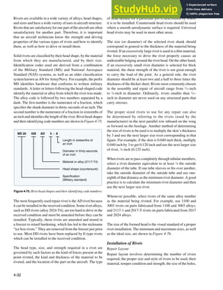
![4-33
1.25 d 1.5 d
1.33 d 1.5 d
1.66 d
.66 d .5 d .33 d
1.25 d 1.4 d 1.5 d
.66 d .6 d .5 d
1.25 d 1.33 d
Minimum Maximum
Preferred
Minimum Maximum
Preferred
Driven Rivet Standards
A, AD, B, DD Rivets
D, E, (KE), M Rivets
Formed
head
dimension
Formed
head
dimension
Predrive
protrusion
Predrive
protrusion
Figure 4-76. Rivet formed head dimensions.
Standard Rivet Alloy Code Markings
Alloy code—A
Alloy—1100 or 3003 aluminum
Head marking—None
Shear strength—10 KSI
Nonstructural uses only
Alloy code—B
Alloy—5056 aluminum
Head marking—raised cross
Shear strength—28 KSI
Alloy code—AD
Alloy—2117 aluminum
Head marking—Dimple
Shear strength—30 KSI
Alloy code—D
Alloy—2017 aluminum
Head marking—Raised dot
Shear strength—38 KSI
38 KSI When driven as received
34 KSI When re-heat treated
Alloy code—DD
Alloy—2024 aluminum
Head marking—Two bars (raised)
Shear strength—41 KSI
Must be driven in “W” condition
(Ice-Box)
Alloy code—E
Alloy—7050 aluminum
Head marking—raised circle
Shear strength—54 KSI
Alloy code—E, [KE*] *Boeing code
Alloy—2017 aluminum
Head marking—Raised ring
Shear strength—43 KSI
Replacement for DD rivet
to be driven in “T” condition
Head marking—None
Shear strength—10 KSI
N t t l l
Head marking—raised circ
Shear strength—54 KSI
Head marking—Raised dot
Shear strength—38 KSI
38 KSI When driven as received
Head marking—Dimple
Shear strength—30 KSI
Head marking—Raised ring
Shear strength—43 KSI
Replacement for DD rivet
Head marking—Two bars (raised
Shear strength—41 KSI
Must be driven in “W” condition
Head marking—raised cross
Shear strength—28 KSI
l
cle
Figure 4-77. Rivet allow strength.
the distances between the holes, and the distance between the
holes and the edges of the patch. Distances are measured in
terms of rivet diameter.
Rivet Length
To determine the total length of a rivet to be installed, the
combined thickness of the materials to be joined must irst
be known. This measurement is known as the grip length.
The total length of the rivet equals the grip length plus the
amount of rivet shank needed to form a proper shop head.
The latter equals one and a half times the diameter of the rivet
shank. Where A is total rivet length, B is grip length, and
C is the length of the material needed to form a shop head,
this formula can be represented as A = B + C. [Figure 4-76]
Rivet Strength
For structural applications, the strength of the replacement
rivets is of primary importance. [Figure 4-77] Rivets made
of material that is lower in strength should not be used as
replacements unless the shortfall is made up by using a larger
rivet. For example, a rivet of 2024-T4 aluminum alloy should
not be replaced with one of 2117-T4 or 2017-T4 aluminum
alloy unless the next larger size is used.
The 2117-T rivet is used for general repair work, since it
requires no heat treatment, is fairly soft and strong, and is
highly corrosion resistant when used with most types of
alloys. Always consult the maintenance manual for correct](https://image.slidesharecdn.com/aircraftmetalstructuralrepair-230807175411-df5215b3/85/Aircraft-Metal-Structural-Repair-pdf-33-320.jpg)
![4-34
Rivet Spacing
6D Distance Between
Rows 6D
Rivet Spacing
4D Distance Between
Rows 4D
Rivet Spacing
6D Distance Between
Rows 3D
Figure 4-78. Acceptable rivet patterns.
Figure 4-79. Minimum edge distance.
2 D
2½ D
2 D + 1/16˝
2½ D + 1/16˝
Protruding head rivets
Countersunk rivets
Edge Distance/Edge
Margin
Minimum Edge
Distance
Preferred Edge
Distance
Section A-A
Section A A
E E
D
D
Incorrect - too close to edge
E = 1½D
Correct E = 2D
A A
Resultant crack Safe
rivet type and material. The type of rivet head to select for
a particular repair job can be determined by referring to the
type used within the surrounding area by the manufacturer.
A general rule to follow on a lush-riveted aircraft is to apply
lush rivets on the upper surface of the wing and stabilizers, on
the lower leading edge back to the spar, and on the fuselage
back to the high point of the wing. Use universal head rivets
in all other surface areas. Whenever possible, select rivets of
the same alloy number as the material being riveted.
Stresses Applied to Rivets
Shear is one of the two stresses applied to rivets. The shear
strength is the amount of force required to cut a rivet that
holds two or more sheets of material together. If the rivet
holds two parts, it is under single shear; if it holds three
sheets or parts, it is under double shear. To determine the
shear strength, the diameter of the rivet to be used must be
found by multiplying the thickness of the skin material by 3.
For example, a material thickness of 0.040 inch multiplied by
3 equals 0.120 inch. In this case, the rivet diameter selected
would be 1
⁄8 (0.125) inch.
Tension is the other stress applied to rivets. The resistance to
tension is called bearing strength and is the amount of tension
required to pull a rivet through the edge of two sheets riveted
together or to elongate the hole.
Rivet Spacing
Rivet spacing is measured between the centerlines of rivets
in the same row. The minimum spacing between protruding
head rivets shall not be less than 31
⁄2 times the rivet diameter.
The minimum spacing between lush head rivets shall not be
less than 4 times the diameter of the rivet. These dimensions
may be used as the minimum spacing except when speciied
differently in a speciic repair procedure or when replacing
existing rivets.
On most repairs, the general practice is to use the same rivet
spacing and edge distance (distance from the center of the
hole to the edge of the material) that the manufacturer used in
the area surrounding the damage. The SRM for the particular
aircraft may also be consulted. Aside from this fundamental
rule, there is no speciic set of rules that governs spacing
of rivets in all cases. However, there are certain minimum
requirements that must be observed.
• When possible, rivet edge distance, rivet spacing, and
distance between rows should be the same as that of
the original installation.
• When new sections are to be added, the edge distance
measured from the center of the rivet should never be
less than 2 times the diameter of the shank; the distance
between rivets or pitch should be at least 3 times the
diameter; and the distance between rivet rows should
never be less than 21
⁄2 times the diameter.
Figure 4-78 illustrates acceptable ways of laying out a rivet
pattern for a repair.
Edge Distance
Edgedistance,alsocallededgemarginbysomemanufacturers,
is the distance from the center of the irst rivet to the edge
of the sheet. It should not be less than 2 or more than 4 rivet
diameters and the recommended edge distance is about 21
⁄2
rivet diameters. The minimum edge distance for universal
rivets is 2 times the diameter of the rivet; the minimum edge
distance for countersunk rivets is 21
⁄2 times the diameter of the
rivet. If rivets are placed too close to the edge of the sheet,
the sheet may crack or pull away from the rivets. If they are
spaced too far from the edge, the sheet is likely to turn up at
the edges. [Figure 4-79]](https://image.slidesharecdn.com/aircraftmetalstructuralrepair-230807175411-df5215b3/85/Aircraft-Metal-Structural-Repair-pdf-34-320.jpg)
![4-35
3D + 1/16"
4D + 1/16"
3/1/2D + 1/16"
4/1/2D + 1/16"
1 and 3 rows protruding head rivet layout
2 row protruding head rivet layout
1 and 3 rows countersunk head rivet layout
2 row countersunk head rivet layout
3D
4D
3/1/2D
4/1/2D
Rivet Spacing Preferred Spacing
Minimum Spacing
Figure 4-80. Rivet spacing.
Rivet pitch
(6 to 8 diameters)
Edge distance
(2 to 21/2 diameters)
Transverse pitch (75 percent of rivet pitch)
Single-row layout
Two-row layout
Three-row layout
Figure 4-81. Rivet layout.
It is good practice to lay out the rivets a little further from the
edge so that the rivet holes can be oversized without violating
the edge distance minimums. Add 1
⁄16-inch to the minimum
edge distance or determine the edge distance using the next
size of rivet diameter.
Two methods for obtaining edge distance:
• The rivet diameter of a protruding head rivet is 3
⁄32-
inch. Multiply 2 times 3
⁄32-inch to obtain the minimum
edge distance, 3
⁄16-inch, add 1
⁄16-inch to yield the
preferred edge distance of 1
⁄4-inch.
• The rivet diameter of a protruding head rivet is 3
⁄32-inch.
Select the next size of rivet, which is 1
⁄8-inch. Calculate
the edge distance by multiplying 2 times 1
⁄8-inch to get
1
⁄4-inch.
Rivet Pitch
Rivet pitch is the distance between the centers of neighboring
rivets in the same row. The smallest allowable rivet pitch is 3
rivet diameters. The average rivet pitch usually ranges from
4 to 6 rivet diameters, although in some instances rivet pitch
could be as large as 10 rivet diameters. Rivet spacing on parts
that are subjected to bending moments is often closer to the
minimum spacing to prevent buckling of the skin between
the rivets. The minimum pitch also depends on the number of
rows of rivets. One-and three-row layouts have a minimum
pitch of 3 rivet diameters, a two-row layout has a minimum
pitch of 4 rivet diameters. The pitch for countersunk rivets
is larger than for universal head rivets. If the rivet spacing
is made at least 1
⁄16-inch larger than the minimum, the rivet
hole can be oversized without violating the minimum rivet
spacing requirement. [Figure 4-80]
Transverse Pitch
Transverse pitch is the perpendicular distance between rivet
rows. It is usually 75 percent of the rivet pitch. The smallest
allowable transverse pitch is 21
⁄2 rivet diameters. The smallest
allowable transverse pitch is 21
⁄2 rivet diameters. Rivet pitch
and transverse pitch often have the same dimension and are
simply called rivet spacing.
Rivet Layout Example
The general rules for rivet spacing, as it is applied to a
straight-row layout, are quite simple. In a one-row layout,
ind the edge distance at each end of the row and then lay
off the rivet pitch (distance between rivets), as shown in
Figure 4-81. In a two-row layout, lay off the irst row, place
the second row a distance equal to the transverse pitch from
the irst row, and then lay off rivet spots in the second row
so that they fall midway between those in the irst row. In
the three-row layout, irst lay off the irst and third rows, then
use a straightedge to determine the second row rivet spots.
When splicing a damaged tube, and the rivets pass completely
through the tube, space the rivets four to seven rivet diameters
apart if adjacent rivets are at right angles to each other, and
space them ive to seven rivet diameters apart if the rivets
are parallel to each other. The irst rivet on each side of the
joint should be no less than 21
⁄2 rivet diameters from the end
of the sleeve.](https://image.slidesharecdn.com/aircraftmetalstructuralrepair-230807175411-df5215b3/85/Aircraft-Metal-Structural-Repair-pdf-35-320.jpg)
![4-36
Figure 4-82. Rivet cutters.
Figure 4-83. Bucking bars.
Rivet Installation Tools
The various tools needed in the normal course of driving
and upsetting rivets include drills, reamers, rivet cutters or
nippers, bucking bars, riveting hammers, draw sets, dimpling
dies or other types of countersinking equipment, rivet guns,
and squeeze riveters. C-clamps, vises, and other fasteners
used to hold sheets together when riveting were discussed
earlier in the chapter. Other tools and equipment needed in the
installation of rivets are discussed in the following paragraphs.
Hand Tools
A variety of hand tools are used in the normal course of
driving and upsetting rivets. They include rivet cutters,
bucking bars, hand riveters, countersinks, and dimpling tools.
Rivet Cutter
The rivet cutter is used to trim rivets when rivets of the
required length are unavailable. [Figure 4-82] To use the
rotary rivet cutter, insert the rivet in the correct hole, place the
required number of shims under the rivet head, and squeeze
the cutter as if it were a pair of pliers. Rotation of the disks
cuts the rivet to give the right length, which is determined
by the number of shims inserted under the head. When using
a large rivet cutter, place it in a vise, insert the rivet in the
proper hole, and cut by pulling the handle, which shears off
the rivet. If regular rivet cutters are not available, diagonal
cutting pliers can be used as a substitute cutter.
Bucking Bar
The bucking bar, sometimes called a dolly, bucking
iron, or bucking block, is a heavy chunk of steel whose
countervibration during installation contributes to proper
rivet installation. They come in a variety of shapes and sizes,
and their weights ranges from a few ounces to 8 or 10 pounds,
depending upon the nature of the work. Bucking bars are
most often made from low-carbon steel that has been case
hardened or alloy bar stock. Those made of better grades of
steel last longer and require less reconditioning.
Bucking faces must be hard enough to resist indentation and
remain smooth, but not hard enough to shatter. Sometimes,
the more complicated bars must be forged or built up by
welding. The bar usually has a concave face to conform to the
shape of the shop head to be made. When selecting a bucking
bar, the irst consideration is shape. [Figure 4-83] If the bar
does not have the correct shape, it deforms the rivet head;
if the bar is too light, it does not give the necessary bucking
weight, and the material may become bulged toward the shop
head. If the bar is too heavy, its weight and the bucking force
may cause the material to bulge away from the shop head.
This tool is used by holding it against the shank end of a rivet
while the shop head is being formed. Always hold the face
of the bucking bar at right angles to the rivet shank. Failure
to do so causes the rivet shank to bend with the irst blows
of the rivet gun and causes the material to become marred
with the inal blows. The bucker must hold the bucking bar
in place until the rivet is completely driven. If the bucking
bar is removed while the gun is in operation, the rivet set
may be driven through the material. Allow the weight of the
bucking bar to do most of the work and do not bear down
too heavily on the shank of the rivet. The operator’s hands
merely guide the bar and supply the necessary tension and
rebound action. Coordinated bucking allows the bucking bar
to vibrate in unison with the gun set. With experience, a high
degree of skill can be developed.
Defective rivet heads can be caused by lack of proper
vibrating action, the use of a bucking bar that is too light or
too heavy, and failure to hold the bucking bar at right angles
to the rivet. The bars must be kept clean, smooth, and well
polished. Their edges should be slightly rounded to prevent
marring the material surrounding the riveting operation.
Hand Rivet Set
A hand rivet set is a tool equipped with a die for driving a
particular type rivet. Rivet sets are available to it every size](https://image.slidesharecdn.com/aircraftmetalstructuralrepair-230807175411-df5215b3/85/Aircraft-Metal-Structural-Repair-pdf-36-320.jpg)
![4-37
100°
82°
Figure 4-84. Countersinks.
Pilot
Cutter
Micro-sleeve Skirt
Locking ring
Figure 4-85. Microstop countersink.
Figure 4-86. Rivet guns.
and shape of rivet head. The ordinary set is made of 1
⁄2-inch
carbon tool steel about 6 inches in length and is knurled
to prevent slipping in the hand. Only the face of the set is
hardened and polished.
Sets for universal rivets are recessed (or cupped) to it the
rivet head. In selecting the correct set, be sure it provides the
proper clearance between the set and the sides of the rivet
head and between the surfaces of the metal and the set. Flush
or lat sets are used for countersunk and lathead rivets. To
seat lush rivets properly, be sure that the lush sets are at
least 1 inch in diameter.
Special draw sets are used to draw up the sheets to eliminate
any opening between them before the rivet is bucked. Each
draw set has a hole 1
⁄32-inch larger than the diameter of the
rivet shank for which it is made. Occasionally, the draw set
and rivet header are incorporated into one tool. The header
part consists of a hole shallow enough for the set to expand
the rivet and head when struck with a hammer.
Countersinking Tool
The countersink is a tool that cuts a cone-shaped depression
around the rivet hole to allow the rivet to set lush with
the surface of the skin. Countersinks are made with angles
to correspond with the various angles of countersunk
rivet heads. The standard countersink has a 100º angle,
as shown in Figure 4-84. Special microstop countersinks
(commonly called stop countersinks) are available that can
be adjusted to any desired depth and have cutters to allow
interchangeable holes with various countersunk angles to
be made. [Figure 4-85] Some stop countersinks also have
a micrometer set mechanism, in 0.001-inch increments, for
adjusting their cutting depths.
Dimpling Dies
Dimpling is done with a male and female die (punch and die
set). The male die has a guide the size of the rivet hole and
with the same degree of countersink as the rivet. The female
die has a hole with a corresponding degree of countersink
into which the male guide its.
Power Tools
The most common power tools used in riveting are the
pneumatic rivet gun, rivet squeezers, and the microshaver.
Pneumatic Rivet Gun
The pneumatic rivet gun is the most common rivet
upsetting tool used in airframe repair work. It is available
in many sizes and types. [Figure 4-86] The manufacturer’s
recommended capacity for each gun is usually stamped on
the barrel. Pneumatic guns operate on air pressure of 90
to 100 pounds per square inch and are used in conjunction
with interchangeable rivet sets. Each set is designed to it
the speciic type of rivet and the location of the work. The
shank of the set is designed to it into the rivet gun. An air-
driven hammer inside the barrel of the gun supplies force to
buck the rivet.
Slow hitting rivet guns that strike from 900 to 2,500 blows
per minute are the most common type. [Figure 4-87] These
blows are slow enough to be easily controlled and heavy
enough to do the job. These guns are sized by the largest rivet
size continuously driven with size often based on the Chicago
Pneumatic Company’s old “X” series. A 4X gun (dash 8 or 1
⁄4
rivet) is used for normal work. The less powerful 3X gun is
used for smaller rivets in thinner structure. 7X guns are used
for large rivets in thicker structures. A rivet gun should upset](https://image.slidesharecdn.com/aircraftmetalstructuralrepair-230807175411-df5215b3/85/Aircraft-Metal-Structural-Repair-pdf-37-320.jpg)
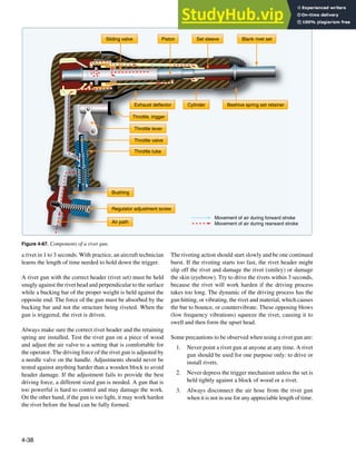
![4-39
Figure 4-88. Rivet headers.
Figure 4-89. Microshaver.
While traditional tooling has changed little in the past 60
years, signiicant changes have been made in rivet gun
ergonomics. Reduced vibration rivet guns and bucking bars
have been developed to reduce the incidence of carpal tunnel
syndrome and enhance operator comfort.
Rivet Sets/Headers
Pneumatic guns are used in conjunction with interchangeable
rivet sets or headers. Each is designed to it the type of rivet
and location of the work. The shank of the rivet header is
designed to it into the rivet gun. An appropriate header must
be a correct match for the rivet being driven. The working
face of a header should be properly designed and smoothly
polished. They are made of forged steel, heat treated to be
tough but not too brittle. Flush headers come in various sizes.
Smaller ones concentrate the driving force in a small area for
maximum eficiency. Larger ones spread the driving force
over a larger area and are used for the riveting of thin skins.
Nonlush headers should it to contact about the center two-
thirds of the rivet head. They must be shallow enough to allow
slight upsetting of the head in driving and some misalignment
without eyebrowing the riveted surface. Care must be taken to
match the size of the rivet. A header that is too small marks
the rivet; while one too large marks the material.
Rivetheadersaremadeinavarietyofstyles.[Figure4-88]The
short, straight header is best when the gun can be brought
close to the work. Offset headers may be used to reach rivets
in obstructed places. Long headers are sometimes necessary
when the gun cannot be brought close to the work due to
structural interference. Rivet headers should be kept clean.
Compression Riveting
Compression riveting (squeezing) is of limited value because
this method of riveting can be used only over the edges of
sheets or assemblies where conditions permit, and where the
reach of the rivet squeezer is deep enough. The three types
of rivet squeezers—hand, pneumatic, and pneudraulic—
operate on the same principles. In the hand rivet squeezer,
compression is supplied by hand pressure; in the pneumatic
rivet squeezer, by air pressure; and in the pneudraulic,
by a combination of air and hydraulic pressure. One jaw
is stationary and serves as a bucking bar, the other jaw is
movable and does the upsetting. Riveting with a squeezer is
a quick method and requires only one operator.
These riveters are equipped with either a C-yoke or an
alligator yoke in various sizes to accommodate any size of
rivet. The working capacity of a yoke is measured by its gap
and its reach. The gap is the distance between the movable
jaw and the stationary jaw; the reach is the inside length
of the throat measured from the center of the end sets. End
sets for rivet squeezers serve the same purpose as rivet sets
for pneumatic rivet guns and are available with the same
type heads, which are interchangeable to suit any type of
rivet head. One part of each set is inserted in the stationary
jaw, while the other part is placed in the movable jaws.
The manufactured head end set is placed on the stationary
jaw whenever possible. During some operations, it may be
necessary to reverse the end sets, placing the manufactured
head end set on the movable jaw.
Microshavers
A microshaver is used if the smoothness of the material (such
as skin) requires that all countersunk rivets be driven within
a speciic tolerance. [Figure 4-89] This tool has a cutter, a
stop, and two legs or stabilizers. The cutting portion of the
microshaver is inside the stop. The depth of the cut can be
adjusted by pulling outward on the stop and turning it in
either direction (clockwise for deeper cuts). The marks on](https://image.slidesharecdn.com/aircraftmetalstructuralrepair-230807175411-df5215b3/85/Aircraft-Metal-Structural-Repair-pdf-39-320.jpg)
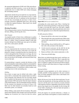
![4-41
Preferred
countersinking
Permissible
countersinking
Unacceptable
countersinking
g
Figure 4-91. Countersinking dimensions.
An important component of team riveting is an eficient
signaling system that communicates the status of the riveting
process. This signaling system usually consists of tapping
the bucking bar against the work and is often called the tap
code. One tap may mean not fully seated, hit it again, while
two taps may mean good rivet, and three taps may mean bad
rivet, remove and drive another. Radio sets are also available
for communication between the technicians.
Once the rivet is installed, there should be no evidence of
rotation of rivets or looseness of riveted parts. After the
trimming operation, examine for tightness. Apply a force
of 10 pounds to the trimmed stem. A tight stem is one
indication of an acceptable rivet installation. Any degree of
looseness indicates an oversize hole and requires replacement
of the rivet with an oversize shank diameter rivet. A rivet
installation is assumed satisfactory when the rivet head is
seated snugly against the item to be retained (0.005-inch
feeler gauge should not go under rivet head for more than
one-half the circumference) and the stem is proved tight.
Countersunk Rivets
An improperly made countersink reduces the strength of a
lush-riveted joint and may even cause failure of the sheet or
the rivet head. The two methods of countersinking commonly
used for lush riveting in aircraft construction and repair are:
• Machine or drill countersinking.
• Dimpling or press countersinking.
The proper method for any particular application depends on
the thickness of the parts to be riveted, the height and angle
of the countersunk head, the tools available, and accessibility.
Countersinking
When using countersunk rivets, it is necessary to make a
conical recess in the skin for the head. The type of countersink
required depends upon the relation of the thickness of the
sheets to the depth of the rivet head. Use the proper degree
and diameter countersink and cut only deep enough for the
rivet head and metal to form a lush surface.
Countersinking is an important factor in the design of fastener
patterns, as the removal of material in the countersinking
process necessitates an increase in the number of fasteners to
assure the required load-transfer strength. If countersinking
is done on metal below a certain thickness, a knife edge with
less than the minimum bearing surface or actual enlarging of
the hole may result. The edge distance required when using
countersunk fasteners is greater than when universal head
fasteners are used.
The general rule for countersinking and flush fastener
installation procedures has been reevaluated in recent years
because countersunk holes have been responsible for fatigue
cracks in aircraft pressurized skin. In the past, the general rule
forcountersinkingheldthatthefastenerheadmustbecontained
within the outer sheet. A combination of countersinks too deep
(creating a knife edge), number of pressurization cycles,
fatigue, deterioration of bonding materials, and working
fasteners caused a high stress concentration that resulted in
skin cracks and fastener failures. In primary structure and
pressurized skin repairs, some manufacturers are currently
recommending the countersink depth be no more than 2
⁄3 the
outer sheet thickness or down to 0.020-inch minimum fastener
shank depth, whichever is greater. Dimple the skin if it is too
thin for machine countersinking. [Figure 4-91]
Keep the rivet high before driving to ensure the force of
riveting is applied to the rivet and not to the skin. If the rivet
is driven while it is lush or too deep, the surrounding skin
is work hardened.
Countersinking Tools
While there are many types of countersink tools, the most
commonly used has an included angle of 100°. Sometimes
types of 82° or 120° are used to form countersunk wells.
[Figure 4-84] A six-fluted countersink works best in
aluminum. There are also four- and three-luted countersinks,](https://image.slidesharecdn.com/aircraftmetalstructuralrepair-230807175411-df5215b3/85/Aircraft-Metal-Structural-Repair-pdf-41-320.jpg)
![4-42
Figure 4-92. Single-flute countersink.
Figure 4-93. Hand squeezers.
but those are harder to control from a chatter standpoint. A
single-lute type, such as those manufactured by the Weldon
Tool Company®, works best for corrosion-resistant steel.
[Figure 4-92]
The microstop countersink is the preferred countersinking
tool. [Figure 4-85] It has an adjustable-sleeve cage that
functions as a limit stop and holds the revolving countersink
in a vertical position. Its threaded and replaceable cutters may
have either a removable or an integral pilot that keeps the
cutter centered in the hole. The pilot should be approximately
0.002-inch smaller than the hole size. It is recommended
to test adjustments on a piece of scrap material before
countersinking repair or replacement parts.
Freehand countersinking is needed where a microstop
countersink cannot it. This method should be practiced on
scrap material to develop the required skill. Holding the
drill motor steady and perpendicular is as critical during this
operation as when drilling.
Chattering is the most common problem encountered when
countersinking. Some precautions that may eliminate or
minimize chatter include:
• Use sharp tooling.
• Use a slow speed and steady irm pressure.
• Use a piloted countersink with a pilot approximately
0.002-inch smaller than the hole.
• Use back-up material to hold the pilot steady when
countersinking thin sheet material.
• Use a cutter with a different number of lutes.
• Pilot drill an undersized hole, countersink, and then
enlarge the hole to inal size.
Dimpling
Dimpling is the process of making an indentation or a
dimple around a rivet hole to make the top of the head
of a countersunk rivet lush with the surface of the metal.
Dimpling is done with a male and female die, or forms, often
called punch and die set. The male die has a guide the size of
the rivet hole and is beveled to correspond to the degree of
countersink of the rivet head. The female die has a hole into
which the male guide its and is beveled to a corresponding
degree of countersink.
When dimpling, rest the female die on a solid surface. Then,
place the material to be dimpled on the female die. Insert the
male die in the hole to be dimpled and, with a hammer, strike
the male die until the dimple is formed. Two or three solid
hammer blows should be suficient. A separate set of dies is
necessary for each size of rivet and shape of rivet head. An
alternate method is to use a countersunk head rivet instead
of the regular male punch die, and a draw set instead of the
female die, and hammer the rivet until the dimple is formed.
Dimpling dies for light work can be used in portable
pneumatic or hand squeezers. [Figure 4-93] If the dies are](https://image.slidesharecdn.com/aircraftmetalstructuralrepair-230807175411-df5215b3/85/Aircraft-Metal-Structural-Repair-pdf-42-320.jpg)
![4-43
Figure 4-94. Table riveter.
1 2 3
2
Gun draw tool Flat gun die
Bucking bar
Male die
Female die
Hole
Dimpled hole
Figure 4-95. Dimpling techniques.
used with a squeezer, they must be adjusted accurately to the
thickness of the sheet being dimpled. A table riveter is also
used for dimpling thin skin material and installing rivets.
[Figure 4-94]
Coin Dimpling
The coin dimpling, or coin pressing, method uses a
countersink rivet as the male dimpling die. Place the female
die in the usual position and back it with a bucking bar. Place
the rivet of the required type into the hole and strike the rivet
with a pneumatic riveting hammer. Coin dimpling should
be used only when the regular male die is broken or not
available. Coin pressing has the distinct disadvantage of the
rivet hole needing to be drilled to correct rivet size before the
dimpling operation is accomplished. Since the metal stretches
during the dimpling operation, the hole becomes enlarged and
the rivet must be swelled slightly before driving to produce
a close it. Because the rivet head causes slight distortions in
the recess, and these are characteristic only to that particular
rivet head, it is wise to drive the same rivet that was used as
the male die during the dimpling process. Do not substitute
another rivet, either of the same size or a size larger.
Radius Dimpling
Radius dimpling uses special die sets that have a radius
and are often used with stationary or portable squeezers.
Dimpling removes no metal and, due to the nestling effect,
gives a stronger joint than the non-lush type. A dimpled joint
reduces the shear loading on the rivet and places more load
on the riveted sheets.
NOTE: Dimpling is also done for lush bolts and other
lush fasteners.
Dimpling is required for sheets that are thinner than the
minimum speciied thickness for countersinking. However,
dimpling is not limited to thin materials. Heavier parts may
be dimpled without cracking by specialized hot dimpling
equipment. The temper of the material, rivet size, and
available equipment are all factors to be considered in
dimpling. [Figure 4-95]
Hot Dimpling
Hot dimpling is the process that uses heated dimpling dies to
ensure the metal lows better during the dimpling process. Hot
dimpling is often performed with large stationary equipment
available in a sheet metal shop. The metal being used is
an important factor because each metal presents different
dimpling problems. For example, 2024-T3 aluminum alloy
can be satisfactorily dimpled either hot or cold, but may crack
in the vicinity of the dimple after cold dimpling because of
hard spots in the metal. Hot dimpling prevents such cracking.
7075-T6 aluminum alloys are always hot dimpled.
Magnesium alloys also must be hot dimpled because, like
7075-T6, they have low formability qualities. Titanium is
another metal that must be hot dimpled because it is tough
and resists forming. The same temperature and dwell time
used to hot dimple 7075-T6 is used for titanium.
100° Combination Predimple and Countersink Method
Metals of different thicknesses are sometimes joined
by a combination of dimpling and countersinking.
[Figure 4-96] A countersink well made to receive a dimple
is called a subcountersink. These are most often seen where
a thin web is attached to heavy structure. It is also used on
thin gap seals, wear strips, and repairs for worn countersinks.](https://image.slidesharecdn.com/aircraftmetalstructuralrepair-230807175411-df5215b3/85/Aircraft-Metal-Structural-Repair-pdf-43-320.jpg)
![4-44
This top sheet is dimpled
Thick bottom material is countersunk
Figure 4-96. Predimple and countersink method.
Top
view
Side
view
Bottom
view
Si
Top
view
w
Bottom
v
v
iew
A. Driven correctly B. Unsteady tool C. Driven excessively D. Separation of sheets E. Unsteady rivet set F. Excessive shank length
Imperfection Cause Remedy Action
None
Cut head
Excessively flat head,
resultant head cracks
Sheet separation
Sloping head
Buckled shank
None
Improperly held tools
Excessive driving, too much pressure on
bucking bar
Work not held firmly together and rivet
shank swelled
a. Bucking bar not held firmly
b. Bucking bar permitted to slide and
bounce over the rivet
Improper rivet length, and E above
None
Hold riveting tools firmly against work
Improve riveting technique
Fasten work firmly together to prevent
slipping
Hold bucking bar firmly without too
much pressure
E above and rivet of proper length
None
Replace rivet
Replace rivet
Replace rivet
Replace rivet
Replace rivet
A
B
C
D
E
F
Damaged
head
Swelled shank
Sloping head Buckled shank
Cracks
Figure 4-97. Rivet defects.
common in 2024-T3. A rough hole or a dimple that
is too deep causes such cracks. A small tolerance is
usually allowed for radial cracks.
• Circumferential cracks—downward bending into the
draw die causes tension stresses in the upper portion
of the metal. Under some conditions, a crack may
be created that runs around the edge of the dimple.
Such cracks do not always show since they may be
underneath the cladding. When found, they are cause
for rejection. These cracks are most common in hot-
dimpled 7075 T6 aluminum alloy material. The usual
cause is insuficient dimpling heat.
Evaluating the Rivet
To obtain high structural eficiency in the manufacture and
repair of aircraft, an inspection must be made of all rivets
before the part is put in service. This inspection consists of
examining both the shop and manufactured heads and the
surrounding skin and structural parts for deformities. A scale
or rivet gauge can be used to check the condition of the upset
rivet head to see that it conforms to the proper requirements.
Deformities in the manufactured head can be detected by the
trained eye alone. [Figure 4-97]
Dimpling Inspection
To determine the quality of a dimple, it is necessary to make
a close visual inspection. Several features must be checked.
The rivet head should it lush and there should be a sharp
break from the surface into the dimple. The sharpness of the
break is affected by dimpling pressure and metal thickness.
Selected dimples should be checked by inserting a fastener to
make sure that the lushness requirements are met. Cracked
dimples are caused by poor dies, rough holes, or improper
heating. Two types of cracks may form during dimpling:
• Radial cracks—start at the edge and spread outward as
the metal within the dimple stretches. They are most](https://image.slidesharecdn.com/aircraftmetalstructuralrepair-230807175411-df5215b3/85/Aircraft-Metal-Structural-Repair-pdf-44-320.jpg)
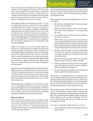
![4-46
1. File a flat area on manufactured head 2. Center punch flat
3. Drill through head using drill one
size smaller than rivet shank
4. Remove weakened head with
machine punch
5. Punch out rivet with machine punch
Rivet Removal
Remove rivets by drilling off the head and punching out the shank as illustrated.
1. File a flat area on the manufactured head of non-flush rivets.
2. Place a block of wood or a bucking bar under both flush and nonflush rivets when center punching the manufactured head.
3. Use a drill that is 1/32 (0.0312) inch smaller than the rivet shank to drill through the head of the rivet. Ensure the drilling
operation does not damage the skin or cut the sides of the rivet hole.
4. Insert a drift punch into the hole drilled in the rivet and tilt the punch to break off the rivet head.
5. Using a drift punch and hammer, drive out the rivet shank. Support the opposite side of the structure to prevent
structural damage.
Figure 4-98. Rivet removal.
2. Drill into the exact center of the rivet head to the
approximate depth of the head.
3. Remove the head by breaking it off. Use a punch as
a lever.
4. Punch out the shank. Use a suitable backup, preferably
wood (or equivalent), or a dedicated backup block. If
the shank does not come out easily, use a small drill
and drill through the shank. Be careful not to elongate
the hole.
Replacing Rivets
Replace rivets with those of the same size and strength
whenever possible. If the rivet hole becomes enlarged,
deformed, or otherwise damaged, drill or ream the hole for
the next larger size rivet. Do not replace a rivet with a type
having lower strength properties, unless the lower strength
is adequately compensated by an increase in size or a greater
number of rivets. It is acceptable to replace 2017 rivets of
3
⁄16-inch diameter or less, and 2024 rivets of 5
⁄32-inch diameter
or less with 2117 rivets for general repairs, provided the
replacement rivets are 1
⁄32-inch greater in diameter than the
rivets they replace.
National Advisory Committee for Aeronautics
(NACA) Method of Double Flush Riveting
A rivet installation technique known as the National Advisory
Committee for Aeronautics (NACA) method has primary
applications in fuel tank areas. [Figure 4-99] To make](https://image.slidesharecdn.com/aircraftmetalstructuralrepair-230807175411-df5215b3/85/Aircraft-Metal-Structural-Repair-pdf-46-320.jpg)
![4-47
Rivet factory head
Shop head formed in countersink
Figure 4-99. NACA riveting method.
.032
.040
.050
.063
.090
.141
.189
.236
.288
.400
3/32
1/8
5/32
3/16
1/4
Rivet Size Minimum Thickness Countersink Diameter
± .005
Figure 4-100. Material thickness minimums, in inches, for NACA
riveting method using 82° countersink.
Figure 4-101. Assorted fasteners.
a NACA rivet installation, the shank is upset into a 82°
countersink. In driving, the gun may be used on either the
head or shank side. The upsetting is started with light blows,
then the force increased and the gun or bar moved on the
shank end so as to form a head inside the countersink well. If
desired, the upset head may be shaved lush after driving. The
optimal strength is achieved by cutting the countersink well
to the dimensions given in Figure 4-100. Material thickness
minimums must be carefully adhered to.
Special Purpose Fasteners
Special purpose fasteners are designed for applications in
which fastener strength, ease of installation, or temperature
properties of the fastener require consideration. Solid shank
rivets have been the preferred construction method for metal
aircraft for many years because they ill up the hole, which
results in good load transfer, but they are not always ideal.
For example, the attachment of many nonstructural parts
(aircraft interior furnishings, looring, deicing boots, etc.) do
not need the full strength of solid shank rivets.
To install solid shank rivets, the aircraft technician must
have access to both sides of a riveted structure or structural
part. There are many places on an aircraft where this access
is impossible or where limited space does not permit the use
of a bucking bar. In these instances, it is not possible to use
solid shank rivets, and special fasteners have been designed
that can be bucked from the front. [Figure 4-101] There are
also areas of high loads, high fatigue, and bending on aircraft.
Although the shear loads of riveted joints are very good, the
tension, or clamp-up, loads are less than ideal.
Special purpose fasteners are sometimes lighter than solid
shank rivets, yet strong enough for their intended use. These
fasteners are manufactured by several corporations and
have unique characteristics that require special installation
tools, special installation procedures, and special removal
procedures. Because these fasteners are often inserted in
locations where one head, usually the shop head, cannot be
seen, they are called blind rivets or blind fasteners.
Typically, the locking characteristics of a blind rivet are not
as good as a driven rivet. Therefore, blind rivets are usually
not used when driven rivets can be installed. Blind rivets
shall not be used:
1. In luid-tight areas.
2. On aircraft in air intake areas where rivet parts may
be ingested by the engine.
3. On aircraft control surfaces, hinges, hinge brackets,
light control actuating systems, wing attachment
ittings, landing gear ittings, on loats or amphibian
hulls below the water level, or other heavily stressed
locations on the aircraft.
NOTE: For metal repairs to the airframe, the use of blind
rivets must be specifically authorized by the airframe
manufacturer or approved by a representative of the Federal
Aviation Administration (FAA).
Blind Rivets
The irst blind fasteners were introduced in 1940 by the
Cherry Rivet Company (now Cherry® Aerospace), and the
aviation industry quickly adopted them. The past decades
have seen a proliferation of blind fastening systems based on
the original concept, which consists of a tubular rivet with
a ixed head and a hollow sleeve. Inserted within the rivet’s
core is a stem that is enlarged or serrated on its exposed end
when activated by a pulling-type rivet gun. The lower end
of the stem extends beyond the inner sheet of metal. This](https://image.slidesharecdn.com/aircraftmetalstructuralrepair-230807175411-df5215b3/85/Aircraft-Metal-Structural-Repair-pdf-47-320.jpg)
![4-48
Figure 4-102. Friction-lock blind rivet.
portion contains a tapered joining portion and a blind head
that has a larger diameter than the stem or the sleeve of the
tubular rivet.
When the pulling force of the rivet gun forces the blind head
upward into the sleeve, its stem upsets or expands the lower
end of the sleeve into a tail. This presses the inner sheet
upward and closes any space that might have existed between
it and the outer sheet. Since the exposed head of the rivet is
held tightly against the outer sheet by the rivet gun, the sheets
of metal are clamped, or clinched, together.
NOTE: Fastener manufacturers use different terminology to
describe the parts of the blind rivet. The terms “mandrel,”
“spindle,” and “stem” are often used interchangeably. For
clarity, the word “stem” is used in this handbook and refers
to the piece that is inserted into the hollow sleeve.
Friction-Locked Blind Rivets
Standard self-plugging blind rivets consist of a hollow sleeve
and a stem with increased diameter in the plug section.
The blind head is formed as the stem is pulled into the
sleeve. Friction-locked blind rivets have a multiple-piece
construction and rely on friction to lock the stem to the
sleeve. As the stem is drawn up into the rivet shank, the
stem portion upsets the shank on the blind side, forming a
plug in the hollow center of the rivet. The excess portion of
the stem breaks off at a groove due to the continued pulling
action of the rivet gun. Metals used for these rivets are 2117-
T4 and 5056-F aluminum alloy. Monel® is used for special
applications.
Many friction-locked blind rivet center stems fall out due to
vibration, which greatly reduces its shear strength. To combat
that problem, most friction-lock blind rivets are replaced by
the mechanical-lock, or stem-lock, type of blind fasteners.
However, some types, such as the Cherry SPR® 3
⁄32-inch
Self-Plugging Rivet, are ideal for securing nutplates located
in inaccessible and hard-to-reach areas where bucking or
squeezing of solid rivets is unacceptable. [Figure 4-102]
Friction-lock blind rivets are less expensive than mechanical-
lock blind rivets and are sometimes used for nonstructural
applications. Inspection of friction-lock blind rivets is
visual. A more detailed discussion on how to inspect riveted
joints can be found in the section, General Repair Practices.
Removal of friction-lock blind rivets consists of punching out
the friction-lock stem and then treating it like any other rivet.
Mechanical-Lock Blind Rivets
The self-plugging, mechanical-lock blind rivet was developed
to prevent the problem of losing the center stem due to
vibration. This rivet has a device on the puller or rivet head
that locks the center stem into place when installed. Bulbed,
self-plugging, mechanically-locked blind rivets form a large,
blind head that provides higher strength in thin sheets when
installed. They may be used in applications where the blind
head is formed against a dimpled sheet.
Manufacturers such as Cherry® Aerospace (CherryMAX®,
CherryLOCK®, Cherry SST®) and Alcoa Fastening Systems
(Huck-Clinch®, HuckMax®, Unimatic®) make many
variations of this of blind rivet. While similar in design, the
tooling for these rivets is often not interchangeable.
The CherryMAX® Bulbed blind rivet is one of the earlier
types of mechanical-lock blind rivets developed. Their main
advantage is the ability to replace a solid shank rivet size
for size. The CherryMAX® Bulbed blind rivet consists of
four parts:
1. A fully serrated stem with break notch, shear ring, and
integral grip adjustment cone.
2. A driving anvil to ensure a visible mechanical lock
with each fastener installation.
3. A separate, visible, and inspectable locking collar that
mechanically locks the stem to the rivet sleeve.
4. A rivet sleeve with recess in the head to receive the
locking collar.
It is called a bulbed fastener due to its large blind side
bearing surface, developed during the installation process.
These rivets are used in thin sheet applications and for use
in materials that may be damaged by other types of blind](https://image.slidesharecdn.com/aircraftmetalstructuralrepair-230807175411-df5215b3/85/Aircraft-Metal-Structural-Repair-pdf-48-320.jpg)
![4-49
1 2 3 4
The CherryMAX®
rivet is
inserted into the prepared
hole. The pulling head
(installation tool) is slipped
over the rivet’s stem.
Applying a firm, steady
pressure, which seats the
rivet head, the installation
tool is then actuated.
The pulling head holds the
rivet sleeve in place as it
begins to pull the rivet stem
into the rivet sleeve. This
pulling action causes the
stem shear ring to upset the
rivet sleeve and form the
bulbed blind head.
The continued pulling action of
the installation tool causes the
stem shear ring to shear from
the main body of the stem as
the stem continues to move
through the rivet sleeve. This
action allows the fastener to
accommodate a minimum of
1/16" variation in structure
thickness. The locking collar
then contacts the driving anvil.
As the stem continues to be
pulled by the action of the
installation tool, the Safe-Lock
locking collar deforms into the
rivet sleeve head recess.
The safe-lock locking collar
fills the rivet sleeve head
recess, locking the stem and
rivet sleeve securely together.
Continued pulling by the
installation tool causes the
stem to fracture at the break
notch, providing a flush,
burr-free, inspectable
installation.
Figure 4-103. CherryMax® installation procedure.
rivets. This rivet features a safe-lock locking collar for more
reliable joint integrity. The rough end of the retained stem
in the center on the manufactured head must never be iled
smooth because it weakens the strength of the lockring, and
the center stem could fall out.
CherryMAX® bulbed rivets are available in three head styles:
universal, 100° countersunk, and 100° reduced shear head
styles. Their lengths are measured in increments of 1
⁄16 inch.
It is important to select a rivet with a length related to the
grip length of the metal being joined. This blind rivet can
be installed using either the Cherry® G750A or the newly
released Cherry® G800 hand riveters, or either the pneumatic-
hydraulic G704B or G747 CherryMAX® power tools. For
installation, please refer to Figure 4-103.
The CherryMAX® mechanical-lock blind rivet is popular
with general aviation repair shops because it features the
one tool concept to install three standard rivet diameters and
their oversize counterparts. [Figure 4-104] CherryMAX®
rivets are available in four nominal diameters: 1
⁄8, 5
⁄32, 3
⁄16, and
1
⁄4-inch and three oversized diameters and four head styles:
universal, 100° lush head, 120° lush head, and NAS1097
lush head. This rivet consists of a blind header, hollow rivet
shell, locking (foil) collar, driving anvil, and pulling stem
complete with wrapped locking collar. The rivet sleeve and
the driving washer blind bulbed header takes up the extended
shank and forms the bucktail.
The stem and rivet sleeve work as an assembly to provide
radial expansion and a large bearing footprint on the blind
side of the fastened surface. The lock collar ensures that the
stem and sleeve remain assembled during joint loading and
unloading. Rivet sleeves are made from 5056 aluminum,
Monel® and INCO 600. The stems are made from alloy
steel, CRES, and INCO® X-750. CherryMAX® rivets have
an ultimate shear strength ranging from 50 KSI to 75 KSI.
Removal of Mechanically Locked Blind Rivets
Mechanically locked blind rivets are a challenge to remove
because they are made from strong, hard metals. Lack of
access poses yet another problem for the aviation technician.
Designed for and used in dificult to reach locations means
there is often no access to the blind side of the rivet or any way
to provide support for the sheet metal surrounding the rivet’s
location when the aviation technician attempts removal.
The stem is mechanically locked by a small lock ring that
needs to be removed irst. Use a small center drill to provide
a guide for a larger drill on top of the rivet stem and drill
away the upper portion of the stem to destroy the lock. Try
to remove the lock ring or use a prick punch or center punch
to drive the stem down a little and remove the lock ring.
After the lock ring is removed, the stem can be driven out
with a drive punch. After the stem is removed, the rivet can
be drilled out in the same way as a solid rivet. If possible,
support the back side of the rivet with a backup block to
prevent damage to the aircraft skin.](https://image.slidesharecdn.com/aircraftmetalstructuralrepair-230807175411-df5215b3/85/Aircraft-Metal-Structural-Repair-pdf-49-320.jpg)

![4-51
Figure 4-105. Hi-Lok®.
• Use a special hollow punch having one or more blades
placed to split the collar. Pry the collar from the groove
and tap out the rivet.
• Sharpen the cutting blades of a pair of nippers. Cut
the collar in two pieces or use nippers at right angles
to the rivet and cut through the small neck.
• A hollow-mill collar cutter can be used in a power hand
drill to cut away enough collar material to permit the
rivet to be tapped out of the work.
The high-shear pin rivet family includes fasteners, such as
the Hi-Lok®, Hi-Tigue®, and Hi-Lite® made by Hi-Shear
Corporation and the CherryBUCK® 95 KSI One-Piece Shear
Pin and Cherry E-Z Buck® Shear Pin made by Cherry®
Aerospace.
Hi-Lok® Fastening System
The threaded end of the Hi-Lok® two-piece fastener contains
a hexagonal shaped recess. [Figure 4-105] The hex tip of an
Allen wrench engages the recess to prevent rotation of the
pin while the collar is being installed. The pin is designed
in two basic head styles. For shear applications, the pin is
made in countersunk style and in a compact protruding head
style. For tension applications, the MS24694 countersunk and
regular protruding head styles are available.
The self-locking, threaded Hi-Lok® collar has an internal
counterbore at the base to accommodate variations in
material thickness. At the opposite end of the collar is a
wrenching device that is torqued by the driving tool until it
shears off during installation, leaving the lower portion of
the collar seated with the proper torque without additional
torque inspection. This shear-off point occurs when a
predetermined preload or clamp-up is attained in the fastener
during installation.
The advantages of Hi-Lok® two-piece fastener include its
light weight, high fatigue resistance, high strength, and its
inability to be overtorqued. The pins, made from alloy steel,
corrosion resistant steel, or titanium alloy, come in many
standard and oversized shank diameters. The collars are made
of aluminum alloy, corrosion resistant steel, or alloy steel.
The collars have wrenching lats, fracture point, threads, and
a recess. The wrenching lats are used to install the collar.
The fracture point has been designed to allow the wrenching
lats to shear when the proper torque has been reached. The
threads match the threads of the pins and have been formed
into an ellipse that is distorted to provide the locking action.
The recess serves as a built-in washer. This area contains a
portion of the shank and the transition area of the fastener.
The hole shall be prepared so that the maximum interference
it does not exceed 0.002-inch. This avoids build up of
excessive internal stresses in the work adjacent to the hole.
The Hi-Lok® pin has a slight radius under its head to increase
fatigue life. After drilling, deburr the edge of the hole to allow
the head to seat fully in the hole. The Hi-Lok® is installed in
interference it holes for aluminum structure and a clearance
it for steel, titanium, and composite materials.
Hi-Tigue® Fastening System
The Hi-Tigue® fastener offers all of the beneits of the Hi-
Lok® fastening system along with a unique bead design that
enhances the fatigue performance of the structure making
it ideal for situations that require a controlled interference
it. The Hi-Tigue® fastener assembly consists of a pin and
collar. These pin rivets have a radius at the transition area.
During installation in an interference it hole, the radius area
will “cold work” the hole. These fastening systems can be
easily confused, and visual reference should not be used for
identiication. Use part numbers to identify these fasteners.
Hi-Lite® Fastening System
The Hi-Lite® fastener is similar in design and principle to
the Hi-Lok® fastener, but the Hi-Lite® fastener has a shorter
transition area between the shank and the irst load-bearing
thread. Hi-Lite® has approximately one less thread. All Hi-
Lite® fasteners are made of titanium.
These differences reduce the weight of the Hi-Lite® fastener
without lessening the shear strength, but the Hi-Lite®
clamping forces are less than that of a Hi-Lok® fastener.
The Hi-Lite® collars are also different and thus are not
interchangeable with Hi-Lok® collars. Hi-Lite® fasteners can
be replaced with Hi-Lok® fasteners for most applications, but
Hi-Loks® cannot be replaced with Hi-Lites®.](https://image.slidesharecdn.com/aircraftmetalstructuralrepair-230807175411-df5215b3/85/Aircraft-Metal-Structural-Repair-pdf-51-320.jpg)
![4-52
Shear and tension
pull-type pins
Shear and tension
stump-type pins
Figure 4-106. Lockbolts.
2
4
6
8
10
12
14
16
18
20
22
24
26
28
30
32
34
36
38
40
42
44
46
48
2
4
6
8
10
12
14
16
18
20
22
24
26
28
30
32
34
36
38
40
42
44
46
48
2
4
6
8
10
12
14
16
18
20
22
24
26
28
30
32
34
36
38
40
42
44
46
INCH SCALE
GRIP SCALE
Figure 4-107. Lockbolt grip gauge.
CherryBUCK® 95 KSI One-Piece Shear Pin
The CherryBUCK® is a bimetallic, one-piece fastener that
combines a 95 KSI shear strength shank with a ductile,
titanium-columbium tail. Theses fasteners are functionally
interchangeable with comparable 6AI-4V titanium alloy
two-piece shear fasteners, but with a number of advantages.
Their one piece design means no foreign object damage
(FOD), it has a 600 °F allowable temperature, and a very
low backside proile.
Lockbolt Fastening Systems
Also pioneered in the 1940s, the lockbolt is a two-piece
fastener that combines the features of a high strength bolt and
a rivet with advantages over each. [Figure 4-106] In general,
a lockbolt is a nonexpanding fastener that has either a collar
swaged into annular locking groves on the pin shank or a type
of threaded collar to lock it in place. Available with either
countersunk or protruding heads, lockbolts are permanent
type fasteners assemblies and consist of a pin and a collar.
A lockbolt is similar to an ordinary rivet in that the locking
collar, or nut, is weak in tension and it is dificult to remove
once installed. Some of the lockbolts are similar to blind
rivets and can be completely installed from one side. Others
are fed into the workpiece with the manufactured head on the
far side. The installation is completed on the near side with
a gun similar to blind rivet gun. The lockbolt is easier and
more quickly installed than the conventional rivet or bolt and
eliminates the use of lockwashers, cotter pins, and special
nuts. The lockbolt is generally used in wing splice ittings,
landing gear ittings, fuel cell ittings, longerons, beams, skin
splice plates, and other major structural attachment.
Often called huckbolts, lockbolts are manufactured by
companies such as Cherry® Aerospace (Cherry® Lockbolt),
Alcoa Fastening Systems (Hucktite® Lockbolt System),
and SPS Technologies. Used primarily for heavily stressed
structures that require higher shear and clamp-up values than
can be obtained with rivets, the lockbolt and Hi-lok® are often
used for similar applications. Lockbolts are made in various
head styles, alloys, and inishes.
The lockbolt requires a pneumatic hammer or pull gun
for installation. Lockbolts have their own grip gauge
and an installation tool is required for their installation.
[Figure 4-107] When installed, the lockbolt is rigidly and
permanently locked in place. Three types of lockbolts are
commonly used: pull-type, stump-type, and blind-type.
The pull-type lockbolt is mainly used in aircraft and primary
and secondary structure. It is installed very rapidly and has
approximately one-half the weight of equivalent AN steel
bolts and nuts. A special pneumatic pull gun is required for
installation of this type lockbolt, which can be performed by
one operator since buckling is not required.
The stump-type lockbolt, although not having the extended
stem with pull grooves, is a companion fastener to the pull-
type lockbolt. It is used primarily where clearance does not
permit effective installation of the pull-type lockbolt. It is
driven with a standard pneumatic riveting hammer, with
a hammer set attached for swaging the collar into the pin
locking grooves, and a bucking bar.
The blind-type lockbolt comes as a complete unit or
assembly and has exceptional strength and sheet pull-together
characteristics. Blind-type lockbolts are used where only
one side of the work is accessible and generally where it is
dificult to drive a conventional rivet. This type lockbolt is
installed in a manner similar to the pull-type lockbolt.
The pins of pull- and stump-type lockbolts are made of
heat-treated alloy steel or high-strength aluminum alloy.
Companion collars are made of aluminum alloy or mild steel.
The blind-type lockbolt consists of a heat-treated alloy steel
pin, blind sleeve, iller sleeve, mild steel collar, and carbon
steel washer.
These fasteners are used in shear and tension applications.
The pull type is more common and can be installed by one
person. The stump type requires a two person installation.
An assembly tool is used to swage the collar onto the serrated
grooves in the pin and break the stem lush to the top of the
collar.](https://image.slidesharecdn.com/aircraftmetalstructuralrepair-230807175411-df5215b3/85/Aircraft-Metal-Structural-Repair-pdf-52-320.jpg)
![4-53
1 2 3 4
2 3 4
Continued force breaks the
pin and ejects the tail. Anvil
returns and disengages from
the swaged collar.
The initial pull draws the work
up tight and pulls that portion
of the shank under the head
into the hole.
Further pull swages the collar
into the locking grooves to
form a permanent lock.
Placed the pin in the hole
from the back side of the
work and slip the collar on.
The hold-off head must be
toward the gun. This allows
the gun to preload the pin
before swaging. Then apply
the gun; the chuck jaws
engage the pull grooves of
the projecting pintail. Hold
the gun loosely and pull the
trigger.
Figure 4-108. Lockbolt installation procedure.
5/32
3/16
1/4
5/16
3/8
Nominal
Fastener Diameter
Y Z
(Ref.)
R
Max.
T
Min.
.324/.161
.280/.208
.374/.295
.492/.404
.604/.507
.136
.164
.224
.268
.039
.253
.303
.400
.473
.576
.037
.039
.037
.110
.120
Lockbolt/Collar Acceptance Criteria
R
Z
T
Y
kbolt/Collar Acceptan
Figure 4-109. Lockbolt inspection.
The easiest way to differentiate between tension and shear
pins is the number of locking groves. Tension pins normally
have four locking grooves and shear pins have two locking
grooves. The installation tooling preloads the pin while
swaging the collar. The surplus end of the pin, called the
pintail, is then fractured.
Installation Procedure
Installation of lockbolts involves proper drilling. The hole
preparation for a lockbolt is similar to hole preparation for a
Hi-Lok®. An interference it is typically used for aluminum
and a clearance it is used for steel, titanium, and composite
materials. [Figure 4-108]
Lockbolt Inspection
After installation, a lockbolt needs to be inspected to
determine if installation is satisfactory. [Figure 4-109]
Inspect the lockbolt as follows:
1. The head must be irmly seated.
2. The collar must be tight against the material and have
the proper shape and size.
3. Pin protrusion must be within limits.
Lockbolt Removal
The best way to remove a lockbolt is to remove the collar and
drive out the pin. The collar can be removed with a special
collar cutter attached to a drill motor that mills off the collar
without damaging the skin. If this is not possible, a collar
splitter or small chisel can be used. Use a backup block on
the opposite side to prevent elongation of the hole.
The Eddie-Bolt® 2 Pin Fastening System
The Eddie-Bolt® 2 looks similar to the Hi-Lok®, but has ive
lutes, equally spaced along a portion of the pin thread area.
A companion threaded collar deforms into the lutes at a
predetermined torque and locks the collar in place. The collar
can be unscrewed using special tooling. This fastening system
can be used in either clearance or interference-it holes.](https://image.slidesharecdn.com/aircraftmetalstructuralrepair-230807175411-df5215b3/85/Aircraft-Metal-Structural-Repair-pdf-53-320.jpg)
![4-54
During the Maxibolt®
installation sequence, the Cherry®
shift washer collapses into itself, leaving a solid washer
that is easily retrieved.
Figure 4-110. Maxibolt® Blind Bolt System installation.
Blind Bolts
Bolts are threaded fasteners that support loads through pre-
drilled holes. Hex, close-tolerance, and internal wrenching
bolts are used in aircraft structural applications. Blind bolts
have a higher strength than blind rivets and are used for
joints that require high strength. Sometimes, these bolts can
be direct replacements for the Hi-Lok® and lockbolt. Many
of the new generation blind bolts are made from titanium
and rated at 90 KSI shear strength, which is twice as much
as most blind rivets.
Determining the correct length of the fastener is critical to
correct installation. The grip length of a bolt is the distance
from the underhead bearing surface to the irst thread. The
grip is the total thickness of material joined by the bolt.
Ideally, the grip length should be a few thousands of an inch
less than the actual grip to avoid bottoming the nut. Special
grip gauges are inserted in the hole to determine the length
of the blind bolt to be used. Every blind bolt system has its
own grip gauge and is not interchangeable with other blind
bolt or rivet systems.
Blind bolts are dificult to remove due to the hardness of
the core bolt. A special removal kit is available from the
manufacturer for removing each type of blind bolt. These kits
make it easier to remove the blind bolt without damaging the
hole and parent structure. Blind bolts are available in a pull
type and a drive type.
Pull-Type Blind Bolt
Several companies manufacture the pull-type of blind bolt
fastening systems. They may differ in some design aspects,
but in general they have a similar function. The pull-type uses
the drive nut concept and is composed of a nut, sleeve, and
a draw bolt. Frequently used blind bolt systems include but
are not limited to the Cherry Maxibolt® Blind Bolt system
and the HuckBolt® fasteners which includes the Ti-Matic®
Blind Bolt and the Unimatic® Advanced Bolt (UAB) blind
bolt systems.
Cherry Maxibolt® Blind Bolt System
The Cherry Maxibolt® blind bolt, available in alloy steel
and A-286 CRES materials, comes in four different nominal
and oversized head styles. [Figure 4-110] One tool and
pulling head installs all three diameters. The blind bolts
create a larger blind side footprint and they provide excellent
performance in thin sheet and nonmetallic applications. The
lush breaking stem eliminates shaving while the extended
grip range accommodates different application thicknesses.
Cherry Maxibolts® are primarily used in structures where
higher loads are required. The steel version is 112 KSI shear.
The A286 version is 95 KSI shear. The Cherry® G83, G84,
or G704 installation tools are required for installation.
Huck Blind Bolt System
The Huck Blind Bolt is a high strength vibration-resistant
fastener. [Figure 4-111] These bolts have been used
successfully in many critical areas, such as engine inlets and
leading edge applications. All fasteners are installed with a
combination of available hand, pneumatic, pneudraulic, or
hydraulic pull-type tools (no threads) for ease of installation.
Huck Blind Bolts can be installed on blind side angle
surfaces up to 5° without loss of performance. The stem is
mechanically locked to provide vibration-resistant FOD-free
installations. The locking collar is forced into a conical pocket
between stem and sleeve, creating high tensile capability. The
lock collar ills the sleeve lock pocket to prevent leakage or
corrosion pockets (crevice corrosion).
Flush head blind bolts are designed to install with a lush
stem break that often requires no trimming for aerodynamic
surfaces. The Huck Blind Bolt is available in high-strength
A286 CRES at 95KSI shear strength in 5
⁄32-inch through 3
⁄8-](https://image.slidesharecdn.com/aircraftmetalstructuralrepair-230807175411-df5215b3/85/Aircraft-Metal-Structural-Repair-pdf-54-320.jpg)
![4-55
1
Rivet inserted into clearance hole—tool is engaged.
2
Expander enters sleeve—upset starts to form.
3
Upset continues to form—lock starts to form.
4
Upset complete—lock completely formed.
5
Pin breaks flush, lock visible—installation complete.
inserted into clearance hole—tool is engaged
nder enters sleeve—upset starts to form.
continues to form—lock starts to form.
complete—lock completely formed.
ck visible—installation com
Lockring (visible after installation)
Expander
Break neck
Gold color = Nominal diameter
Silver color = Offset diameter
Drive anvil washer
Pull grooves
Retention splines
Figure 4-111. Huck blind bolt system.
Figure 4-112. Drive nut blind bolt.
Figure 4-113. Drive nut blind bolt installation tool.
inch diameters in 100° lush tension and protruding head.
Also available are shear lush heads in 3
⁄16-inch diameter.
A286 CRES Huck Blind Bolts are also available in 1
⁄64-inch
oversize diameters for repair applications.
Drive Nut-Type of Blind Bolt
Jo-bolts, Visu-lok®, Composi-Lok®, OSI Bolt®, and Radial-
Lok® fasteners use the drive nut concept and are composed of
a nut, sleeve, and a draw bolt. [Figure 4-112] These types of
blind bolts are used for high strength applications in metals
and composites when there is no access to the blind side.
Available in steel and titanium alloys, they are installed with
special tooling. Both powered and hand tooling is available.
During installation, the nut is held stationary while the core
bolt is rotated by the installation tooling. The rotation of the
core bolt draws the sleeve into the installed position and
continues to retain the sleeve for the life of the fastener. The
bolt has left hand threads and driving lats on the threaded
end. A break-off relief allows the driving portion of the
bolt to break off when the sleeve is properly seated. These
types of bolts are available in many different head styles,
including protruding head, 100° lush head, 130° lush head,
and hex head.
Use the grip gauge available for the type of fastener and
select the bolt grip after careful determination of the
material thickness. The grip of the bolt is critical for correct
installation. [Figure 4-113]](https://image.slidesharecdn.com/aircraftmetalstructuralrepair-230807175411-df5215b3/85/Aircraft-Metal-Structural-Repair-pdf-55-320.jpg)
![4-56
Figure 4-114. Rivet nut installation.
5/32
#12
#2
.155–.157
.189–.193
.221–.226
No. 4
No. 6
No. 8
Rivnut®
Size Drill Size Hole Tolerance
Figure 4-115. Recommended hole sizes for rivets and nuts.
Installation procedure:
1. Install the fastener into the hole, and place the
installation tooling over the screw (stem) and nut.
2. Apply torque to the screw with the installation tool
while keeping the drive nut stationary. The screw
continues to advance through the nut body causing
the sleeve to be drawn up over the tapered nose of
the nut. When the sleeve forms tightly against the
blind side of the structure, the screw fractures in the
break groove. The stem of Jo-bolts, Visu-lok®, and
Composi-Lok® II fasteners does not break off lush
with the head. A screw break-off shaver tool must be
used if a lush installation is required. The stem of the
newer Composi-Lok3® and OSI Bolt® break off lush.
Tapered Shank Bolt
Tapered shank bolts, such as the Taper-Lok®, are lightweight,
high strength shear or tension bolts. This bolt has a tapered
shank designed to provide an interference it upon installation.
Tapered shank bolts can be identiied by a round head (rather
than a screwdriver slot or wrench lats) and a threaded shank.
The Taper-Lok® is comprised of a tapered, conical-shank
fastener, installed into a precision tapered hole. The use of
tapered shank bolts is limited to special applications such as
high stress areas of fuel tanks. It is important that a tapered
bolt not be substituted for any other type of fastener in repairs.
It is equally as important not to substitute any other type of
fastener for a tapered bolt.
Tapered shank bolts look similar to Hi-Lok® bolts after
installation, but the tapered shank bolts do not have the hex
recess at the threaded end of the bolt. Tapered shank bolts
are installed in precision-reamed holes, with a controlled
interference it. The interference it compresses the material
around the hole that results in excellent load transfer, fatigue
resistance, and sealing. The collar used with the tapered shank
bolts has a captive washer, and no extra washers are required.
New tapered shank bolt installation or rework of tapered shank
bolt holes needs to be accomplished by trained personnel.
Properly installed, these bolts become tightly wedged and do
not turn while torque is applied to the nut.
Sleeve Bolts
Sleeve bolts are used for similar purposes as tapered shank
bolts, but are easier to install. Sleeve bolts, such as the two
piece SLEEVbolt®, consist of a tapered shank bolt in an
expandable sleeve. The sleeve is internally tapered and
externally straight. The sleeve bolt is installed in a standard
tolerance straight hole. During installation, the bolt is forced
into the sleeve. This action expands the sleeve which ills
the hole. It is easier to drill a straight tolerance hole than it
is to drill the tapered hole required for a tapered shank bolt.
Rivet Nut
The rivet nut is a blind installed, internally threaded rivet
invented in 1936 by the Goodrich Rubber Company for the
purpose of attaching a rubber aircraft wing deicer extrusion
to the leading edge of the wing. The original rivet nut is the
Rivnut® currently manufactured by Bollhoff Rivnut Inc. The
Rivnut® became widely used in the military and aerospace
markets because of its many design and assembly advantages.
Rivet nuts are used for the installation of fairings, trim, and
lightly loaded ittings that must be installed after an assembly
is completed. [Figure 4-114] Often used for parts that are
removed frequently, the rivet nut is available in two types:
countersunk or lat head. Installed by crimping from one side,
the rivet nut provides a threaded hole into which machine
screws can be installed. Where a lush it is required, the
countersink style can be used. Rivet nuts made of alloy steel
are used when increased tensile and shear strength is required.
Hole Preparation
Flat head rivet nuts require only the proper size of hole while
lush installation can be made into either countersunk or
dimpled skin. Metal thinner than the rivet nut head requires
a dimple. The rivet nut size is selected according to the
thickness of the parent material and the size of screw to be
used. The part number identiies the type of rivet nut and the
maximum grip length. Recommended hole sizes are shown
in Figure 4-115.](https://image.slidesharecdn.com/aircraftmetalstructuralrepair-230807175411-df5215b3/85/Aircraft-Metal-Structural-Repair-pdf-56-320.jpg)
![4-57
Figure 4-116. Rivetless pull-through nutplate.
Figure 4-117. Aircraft formed at a factory.
Correct installation requires good hole preparation, removal
of burrs, and holding the sheets in contact while heading.
Like any sheet metal fastener, a rivet nut should it snugly
into its hole.
Blind Fasteners (Nonstructural)
Pop Rivets
Common pull-type pop rivets, produced for non-aircraft-
related applications, are not approved for use on certiicated
aircraft structures or components. However, some homebuilt
noncertiicated aircraft use pull-type rivets for their structure.
These types of rivets are typically made of aluminum and
can be installed with hand tools.
Pull Through Nutplate Blind Rivet
Nutplate blind rivets are used where the high shear strength
of solid rivets is not required or if there is no access to install
a solid rivet. The 3
⁄32-inch diameter blind rivet is most often
used. The nut plate blind rivet is available with the pull-
through and self-plugging locked spindle. [Figure 4-116]
The new Cherry® Rivetless Nut Plate, which replaces
standard riveted nutplates, features a retainer that does not
require laring. This proprietary design eliminates the need for
two additional rivet holes, as well as reaming, counterboring,
and countersinking steps.
Forming Process
Before a part is attached to the aircraft during either
manufacture or repair, it has to be shaped to it into place.
This shaping process is called forming and may be a simple
process, such as making one or two holes for attaching; it may
be a complex process, such as making shapes with complex
curvatures. Forming, which tends to change the shape or
contour of a lat sheet or extruded shape, is accomplished
by either stretching or shrinking the material in a certain
area to produce curves, langes, and various irregular shapes.
Since the operation involves altering the shape of the stock
material, the amount of shrinking and stretching almost
entirely depends on the type of material used. Fully annealed
(heated and cooled) material can withstand considerably more
stretching and shrinking and can be formed at a much smaller
bend radius than when it is in any of the tempered conditions.
When aircraft parts are formed at the factory, they are
made on large presses or by drop hammers equipped with
dies of the correct shape. Factory engineers, who designate
speciications for the materials to be used to ensure the
inished part has the correct temper when it leaves the
machines, plan every part. Factory draftsmen prepare a layout
for each part. [Figure 4-117]
Forming processes used on the flight line and those
practiced in the maintenance or repair shop cannot duplicate
a manufacturer’s resources, but similar techniques of
factory metal working can be applied in the handcrafting of
repair parts.
Forming usually involves the use of extremely light-gauge
alloys of a delicate nature that can be readily made useless by
coarse and careless workmanship. A formed part may seem
outwardly perfect, yet a wrong step in the forming procedure
may leave the part in a strained condition. Such a defect may
hasten fatigue or may cause sudden structural failure.
Of all the aircraft metals, pure aluminum is the most easily
formed. In aluminum alloys, ease of forming varies with
the temper condition. Since modern aircraft are constructed
chiely of aluminum and aluminum alloys, this section deals
with the procedures for forming aluminum or aluminum alloy
parts with a brief discussion of working with stainless steel,
magnesium, and titanium.
Most parts can be formed without annealing the metal,
but if extensive forming operations, such as deep draws](https://image.slidesharecdn.com/aircraftmetalstructuralrepair-230807175411-df5215b3/85/Aircraft-Metal-Structural-Repair-pdf-57-320.jpg)
![4-58
Figure 4-118. Stretch forming metal.
Figure 4-119. Shrink forming metal.
(large folds) or complex curves, are planned, the metal
should be in the dead soft or annealed condition. During
the forming of some complex parts, operations may need
to be stopped and the metal annealed before the process
can be continued or completed. For example, alloy 2024
in the “0” condition can be formed into almost any shape
by the common forming operations, but it must be heat
treated afterward.
Forming Operations and Terms
Forming requires either stretching or shrinking the metal, or
sometimes doing both. Other processes used to form metal
include bumping, crimping, and folding.
Stretching
Stretching metal is achieved by hammering or rolling metal
under pressure. For example, hammering a lat piece of metal
causes the material in the hammered area to become thinner in
that area. Since the amount of metal has not been decreased,
the metal has been stretched. The stretching process thins,
elongates, and curves sheet metal. It is critical to ensure the
metal is not stretched too much, making it too thin, because
sheet metal does not rebound easily. [Figure 4-118]
Stretching one portion of a piece of metal affects the
surrounding material, especially in the case of formed and
extruded angles. For example, hammering the metal in the
horizontal lange of the angle strip over a metal block causes
its length to increase (stretched), making that section longer
than the section near the bend. To allow for this difference in
length, the vertical lange, which tends to keep the material
near the bend from stretching, would be forced to curve away
from the greater length.
Shrinking
Shrinking metal is much more dificult than stretching it.
During the shrinking process, metal is forced or compressed
into a smaller area. This process is used when the length of
a piece of metal, especially on the inside of a bend, is to be
reduced. Sheet metal can be shrunk in by hammering on a
V-block or by crimping and then using a shrinking block.
To curve the formed angle by the V-block method, place the
angle on the V-block and gently hammer downward against
the upper edge directly over the ”V.” While hammering,
move the angle back and forth across the V-block to compress
the material along the upper edge. Compression of the
material along the upper edge of the vertical lange will cause
the formed angle to take on a curved shape. The material in
the horizontal lange will merely bend down at the center, and
the length of that lange will remain the same. [Figure 4-119]
To make a sharp curve or a sharply bent langed angle,
crimping and a shrinking block can be used. In this process,
crimps are placed in the one lange, and then by hammering
the metal on a shrinking block, the crimps are driven, or
shrunk, one at a time.
Coldshrinkingrequiresthecombinationofahardsurface,such
as wood or steel, and a soft mallet or hammer because a steel
hammer over a hard surface stretches the metal, as opposed to
shrinking it. The larger the mallet face is, the better.](https://image.slidesharecdn.com/aircraftmetalstructuralrepair-230807175411-df5215b3/85/Aircraft-Metal-Structural-Repair-pdf-58-320.jpg)
![4-59
Figure 4-120. Crimping metal.
Radius (R)
Leg
Setback (90° bend) R + 1
Base measurement
Mold point
Bend allowance (BA)
Mold line (ML) F L A T
F
L
A
T
Thickness (T)
Bend tangent line (BL)
FLANGE
Bend tangent
line dimension
(BTLD)
MLD
BTLD
MLD
R
T
SB
SB
Mold point
A
B
C
Figure 4-121. Bend allowance terminology.
Bumping
Bumping involves shaping or forming malleable metal by
hammering or tapping—usually with a rubber, plastic, or
rawhide mallet. During this process, the metal is supported by
a dolly, a sandbag, or a die. Each contains a depression into
which hammered portions of the metal can sink. Bumping
can be done by hand or by machine.
Crimping
Crimping is folding, pleating, or corrugating a piece of sheet
metal in a way that shortens it or turning down a lange on
a seam. It is often used to make one end of a piece of stove
pipe slightly smaller so that one section may be slipped into
another. Crimping one side of a straight piece of angle iron
with crimping pliers causes it to curve. [Figure 4-120]
Folding Sheet Metal
Folding sheet metal is to make a bend or crease in sheets,
plates, or leaves. Folds are usually thought of as sharp,
angular bends and are generally made on folding machines
such as the box and pan brake discussed earlier in this chapter.
Layout and Forming
Terminology
The following terms are commonly used in sheet metal
forming and flat pattern layout. Familiarity with these
terms aids in understanding how bend calculations are used
in a bending operation. Figure 4-121 illustrates most of
these terms.
Base measurement—the outside dimensions of a formed part.
Base measurement is given on the drawing or blueprint or
may be obtained from the original part.
Leg—the longer part of a formed angle.
Flange—the shorter part of a formed angle—the opposite of
leg. If each side of the angle is the same length, then each
is known as a leg.
Grain of the metal—natural grain of the material is formed
as the sheet is rolled from molten ingot. Bend lines should be
made to lie at a 90˚ angle to the grain of the metal if possible.
Bend allowance (BA)—refers to the curved section of
metal within the bend (the portion of metal that is curved in
bending). The bend allowance may be considered as being
the length of the curved portion of the neutral line.](https://image.slidesharecdn.com/aircraftmetalstructuralrepair-230807175411-df5215b3/85/Aircraft-Metal-Structural-Repair-pdf-59-320.jpg)
![4-60
Neutral line
Figure 4-122. Neutral line.
Bend radius—the arc is formed when sheet metal is bent. This
arc is called the bend radius. The bend radius is measured
from a radius center to the inside surface of the metal. The
minimum bend radius depends on the temper, thickness, and
type of material. Always use a Minimum Bend Radius Table
to determine the minimum bend radius for the alloy that is
going to be used. Minimum bend radius charts can be found
in manufacturer’s maintenance manuals.
Bend tangent line (BL)—the location at which the metal starts
to bend and the line at which the metal stops curving. All the
space between the band tangent lines is the bend allowance.
Neutral axis—an imaginary line that has the same length
after bending as it had before bending. [Figure 4-122] After
bending, the bend area is 10 to 15 percent thinner than before
bending. This thinning of the bend area moves the neutral
line of the metal in towards the radius center. For calculation
purposes, it is often assumed that the neutral axis is located
at the center of the material, although the neutral axis is not
exactly in the center of the material. However, the amount
of error incurred is so slight that, for most work, assuming
it is at the center is satisfactory.
Mold line (ML)—an extension of the lat side of a part
beyond the radius.
Mold line dimension (MLD)—the dimension of a part made
by the intersection of mold lines. It is the dimension the part
would have if its corners had no radius.
Mold point—the point of intersection of the mold lines. The
mold point would be the outside corner of the part if there
were no radius.
K-Factor—the percentage of the material thickness where
there is no stretching or compressing of the material, such as
the neutral axis. This percentage has been calculated and is
one of 179 numbers on the K chart corresponding to one of
the angles between 0° and 180° to which metal can be bent.
[Figure 4-123] Whenever metal is to be bent to any angle
other than 90° (K-factor of 90° equal to 1), the corresponding
K-factor number is selected from the chart and is multiplied
by the sum of the radius (R) and the thickness (T) of the metal.
The product is the amount of setback (see next paragraph)
for the bend. If no K chart is available, the K-factor can be
calculated with a calculator by using the following formula:
the K value is the tangent of one-half the bend angle.
Setback (SB)—the distance the jaws of a brake must be
setback from the mold line to form a bend. In a 90° bend,
SB = R + T (radius of the bend plus thickness of the metal).
The setback dimension must be determined prior to making
the bend because setback is used in determining the location
of the beginning bend tangent line. When a part has more
than one bend, setback must be subtracted for each bend. The
majority of bends in sheet metal are 90° bends. The K-factor
must be used for all bends that are smaller or larger than 90°.
SB = K(R+T)
Sight line—also called the bend or brake line, it is the layout
line on the metal being formed that is set even with the nose
of the brake and serves as a guide in bending the work.
Flat—that portion of a part that is not included in the bend. It
is equal to the base measurement (MLD) minus the setback.
Flat = MLD – SB
Closed angle—an angle that is less than 90° when measured
between legs, or more than 90° when the amount of bend is
measured.
Open angle—an angle that is more than 90° when measured
between legs, or less than 90° when the amount of bend is
measured.
Total developed width (TDW)—the width of material
measured around the bends from edge to edge. Finding the
TDW is necessary to determine the size of material to be
cut. The TDW is less than the sum of mold line dimensions
since the metal is bent on a radius and not to a square corner
as mold line dimensions indicate.
Layout or Flat Pattern Development
To prevent any waste of material and to get a greater degree
of accuracy in the inished part, it is wise to make a layout
or lat pattern of a part before forming it. Construction of
interchangeable structural and nonstructural parts is achieved
by forming lat sheet stock to make channel, angle, zee, or
hat section members. Before a sheet metal part is formed,
make a lat pattern to show how much material is required](https://image.slidesharecdn.com/aircraftmetalstructuralrepair-230807175411-df5215b3/85/Aircraft-Metal-Structural-Repair-pdf-60-320.jpg)
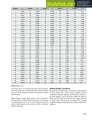
![4-62
Isometric view
Scale: 3:2
.04
R=.16
2.0
1.0
R
R=.16
2 0
2.0
Left view
Scale: 3:2
04
.04
Figure 4-124. U-channel example.
The radius of bend of a sheet of material is the radius of the
bend as measured on the inside of the curved material. The
minimum radius of bend of a sheet of material is the sharpest
curve, or bend, to which the sheet can be bent without
critically weakening the metal at the bend. If the radius of
bend is too small, stresses and strains weaken the metal and
may result in cracking.
A minimum radius of bend is speciied for each type of
aircraft sheet metal. The minimum bend radius is affected
by the kind of material, thickness of the material, and temper
condition of the material. Annealed sheet can be bent to a
radius approximately equal to its thickness. Stainless steel and
2024-T3 aluminum alloy require a fairly large bend radius.
Bending a U-Channel
To understand the process of making a sheet metal layout,
the steps for determining the layout of a sample U-channel
will be discussed. [Figure 4-124] When using bend
allowance calculations, the following steps for inding the
total developed length can be computed with formulas,
charts, or computer-aided design (CAD) and computer-aided
manufacturing (CAM) software packages. This channel is
made of 0.040-inch 2024-T3 aluminum alloy.
Step 1: Determine the Correct Bend Radius
Minimum bend radius charts are found in manufacturers’
maintenance manuals. A radius that is too sharp cracks the
material during the bending process. Typically, the drawing
indicates the radius to use, but it is a good practice to double
check. For this layout example, use the minimum radius
chart in Figure 4-125 to choose the correct bend radius for
the alloy, temper, and the metal thickness. For 0.040, 2024-
T3 the minimum allowable radius is 0.16-inch or 5
⁄32-inch.
Step 2: Find the Setback
The setback can be calculated with a formula or can be found
in a setback chart available in aircraft maintenance manuals
or Source, Maintenance, and Recoverability books (SMRs).
[Figure 4-126]
Using a Formula to Calculate the Setback
SB = setback
K = K-factor (K is 1 for 90° bends)
R = inside radius of the bend
T = material thickness
Since all of the angles in this example are 90° angles, the
setback is calculated as follows:
SB = K(R+T) = 0.2 inches
NOTE: K = 1 for a 90° bend. For other than a 90° bend, use
a K-factor chart.
Using a Setback Chart to Find the Setback
The setback chart is a quick way to ind the setback and is
useful for open and closed bends, because there is no need
to calculate or ind the K-factor. Several software packages
and online calculators are available to calculate the setback.
These programs are often used with CAD/CAM programs.
[Figure 4-126]
• Enter chart at the bottom on the appropriate scale with
the sum of the radius and material thickness.
• Read up to the bend angle.
• Find the setback from corresponding scale on the left.
Example:
• Material thickness is 0.063-inch.
• Bend angle is 135°.
• R + T = 0.183-inch.
Find 0.183 at the bottom of the graph. It is found in the
middle scale.
• Read up to a bend angle of 135°.
• Locate the setback at the left hand side of the graph
in the middle scale (0.435-inch). [Figure 4-126]
Step 3: Find the Length of the Flat Line Dimension
The lat line dimension can be found using the formula:
Flat = MLD – SB
MLD = mold line dimension
SB = setback
The lats, or lat portions of the U-channel, are equal to the
mold line dimension minus the setback for each of the sides,
and the mold line length minus two setbacks for the center
lat. Two setbacks need to be subtracted from the center lat
because this lat has a bend on either side.](https://image.slidesharecdn.com/aircraftmetalstructuralrepair-230807175411-df5215b3/85/Aircraft-Metal-Structural-Repair-pdf-62-320.jpg)
![4-63
.012
.016
.020
.025
.032
.040
.050
.063
.071
.080
.090
.100
.125
.160
.190
.250
.312
.375
.03
.03
.03
.03
.03
.06
.06
.09
.12
.16
.19
.22
.25
.31
.38
.62
1.25
1.38
.03
.03
.12
.16
.19
.22
.25
.31
.38
.44
.50
.62
.88
1.25
1.38
2.00
2.50
2.50
.06
.09
.09
.09
.12
.16
.19
.25
.31
.38
.44
.50
.62
.75
1.00
1.25
1.50
1.88
.03
.03
.03
.03
.03
.06
.06
.06
.09
.09
.09
.12
.12
.16
.19
.31
.44
.44
.03
.03
.03
.06
.06
.09
.12
.16
.16
.19
.22
.25
.31
.44
.56
.75
1.38
1.50
.06
.09
.09
.12
.12
.16
.19
.22
.25
.31
.38
.44
.50
.75
1.00
1.25
1.50
1.88
Thickness
CHART 204
MINIMUM BEND RADIUS FOR ALUMINUM ALLOYS
Bend radius is designated to the inside of the bend. All dimensions are in inches.
7178-0
2024-0
5052-H34
6061-T4
7075-0
7075-T6 2024-T6
5052-0
6061-0
5052-H32
6061-T6 2024-T3
2024-T4
Figure 4-125. Minimum bend radius (from the Raytheon Aircraft Structural Inspection and Repair Manual).
The lat dimension for the sample U-channel is calculated in
the following manner:
Flat dimension = MLD – SB
Flat 1 = 1.00-inch – 0.2-inch = 0.8-inch
Flat 2 = 2.00-inch – (2 × 0.2-inch) = 1.6-inch
Flat 3 = 1.00-inch – 0.2-inch = 0.8-inch
Step 4: Find the Bend Allowance
When making a bend or fold in a piece of metal, the bend
allowance or length of material required for the bend must be
calculated. Bend allowance depends on four factors: degree
of bend, radius of the bend, thickness of the metal, and type
of metal used.
The radius of the bend is generally proportional to the
thickness of the material. Furthermore, the sharper the radius
of bend, the less the material that is needed for the bend. The
type of material is also important. If the material is soft, it
can be bent very sharply; but if it is hard, the radius of bend
is greater, and the bend allowance is greater. The degree
of bend affects the overall length of the metal, whereas the
thickness inluences the radius of bend.
Bending a piece of metal compresses the material on the
inside of the curve and stretches the material on the outside
of the curve. However, at some distance between these
two extremes lies a space which is not affected by either
force. This is known as the neutral line or neutral axis and
occurs at a distance approximately 0.445 times the metal
thickness (0.445 × T) from the inside of the radius of the
bend. [Figure 4-127]
The length of this neutral axis must be determined so that
suficient material can be provided for the bend. This is called
the bend allowance. This amount must be added to the overall
length of the layout pattern to ensure adequate material for
the bend. To save time in calculation of the bend allowance,
formulas and charts for various angles, radii of bends,
material thicknesses, and other factors have been developed.
Formula 1: Bend Allowance for a 90° Bend
To the radius of bend (R) add 1
⁄2 the thickness of the metal
(1
⁄2T). This gives R + 1
⁄2T, or the radius of the circle of the
neutral axis. [Figure 4-128] Compute the circumference
of this circle by multiplying the radius of the neutral line
(R + 1
⁄2T) by 2π (NOTE: π = 3.1416): 2π (R + 1
⁄2T). Since a](https://image.slidesharecdn.com/aircraftmetalstructuralrepair-230807175411-df5215b3/85/Aircraft-Metal-Structural-Repair-pdf-63-320.jpg)
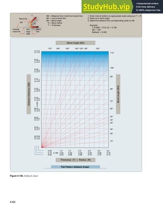
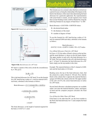
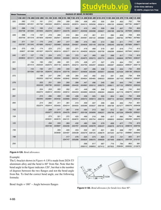
![4-67
0.80 0.80
1.60
0.27 0.27
Bend
allowance
Flat
1
Flat 2
Flat
3
Bend
allowance
Figure 4-131. Flat pattern layout.
The actual bend is 60°. To ind the correct bend radius for a
60° bend of material 0.040-inches thick, use the following
procedure.
1. Go to the left side of the table and ind 0.040-inch.
2. Go to the right and locate the bend radius of 0.16-inch
(0.156-inch).
3. Note the bottom number in the block (0.003034).
4. Multiply this number by the bend angle:
0.003034 × 60 = 0.18204
Step 5: Find the Total Developed Width of the Material
The total developed width (TDW) can be calculated when
the dimensions of the lats and the bend allowance are found.
The following formula is used to calculate TDW:
TDW = Flats + (bend allowance × number of bends)
For the U-channel example, this gives:
TDW = Flat 1 + Flat 2 + Flat 3 + (2 × BA)
TDW = 0.8 + 1.6 + 0.8 + (2 × 0.27)
TDW = 3.74-inches
Note that the amount of metal needed to make the channel
is less than the dimensions of the outside of the channel
(total of mold line dimensions is 4 inches). This is because
the metal follows the radius of the bend rather than going
from mold line to mold line. It is good practice to check
that the calculated TDW is smaller than the total mold line
dimensions. If the calculated TDW is larger than the mold
line dimensions, the math was incorrect.
Step 6: Flat Pattern Lay Out
After a lat pattern layout of all relevant information is made,
the material can be cut to the correct size, and the bend tangent
lines can be drawn on the material. [Figure 4-131]
Step 7: Draw the Sight Lines on the Flat Pattern
The pattern laid out in Figure 4-131 is complete, except
for a sight line that needs to be drawn to help position
the bend tangent line directly at the point where the bend
should start. Draw a line inside the bend allowance area that
is one bend radius away from the bend tangent line that is
placed under the brake nose bar. Put the metal in the brake
under the clamp and adjust the position of the metal until
the sight line is directly below the edge of the radius bar.
[Figure 4-132] Now, clamp the brake on the metal and raise
the leaf to make the bend. The bend begins exactly on the
bend tangent line.
NOTE: A common mistake is to draw the sight line in the
middle of the bend allowance area, instead of one radius
away from the bend tangent line that is placed under the
brake nose bar.
Using a J-Chart To Calculate Total Developed
Width
The J-chart, often found in the SRM, can be used to determine
bend deduction or setback and the TDW of a lat pattern
layout when the inside bend radius, bend angle, and material
thickness are known. [Figure 4-133] While not as accurate as
the traditional layout method, the J-chart provides suficient
information for most applications. The J-chart does not
require dificult calculations or memorized formulas because
the required information can be found in the repair drawing
or can be measured with simple measuring tools.
When using the J-chart, it is helpful to know whether the
angle is open (greater than 90°) or closed (less than 90°)
because the lower half of the J-chart is for open angles and
the upper half is for closed angles.
How To Find the Total Developed Width Using a
J-Chart
• Place a straightedge across the chart and connect the
bend radius on the top scale with the material thickness
on the bottom scale. [Figure 4-133]
• Locate the angle on the right hand scale and follow
this line horizontally until it meets the straight edge.
• The factor X (bend deduction) is then read on the
diagonally curving line.
• Interpolate when the X factor falls between lines.](https://image.slidesharecdn.com/aircraftmetalstructuralrepair-230807175411-df5215b3/85/Aircraft-Metal-Structural-Repair-pdf-67-320.jpg)
![4-68
B
e
n
d
t
a
n
g
e
n
t
l
i
n
e
s
Brake
Sight line
The sight line is located one
radius inside the bend tangent
line that is placed in the brake. Bend tangent lines
Sight line looking straight
down the nose radius bar
Brake
nose
Figure 4-132. Sight line.
• Add up the mold line dimensions and subtract the X
factor to ind the TDW.
Example 1
Bend radius = 0.22-inch
Material thickness = 0.063-inch
Bend angle = 90º
ML 1 = 2.00/ML 2 = 2.00
Use a straightedge to connect the bend radius (0.22-inch) at
the top of the graph with the material thickness at the bottom
(0.063-inch). Locate the 90° angle on the right hand scale and
follow this line horizontally until it meets the straightedge.
Follow the curved line to the left and ind 0.17 at the left side.
The X factor in the drawing is 0.17-inch. [Figure 4-134]
Total developed width =
(Mold line 1 + Mold line 2) – X factor
Total developed width = (2 + 2) – .17 = 3.83-inches
Example 2
Bend radius = 0.25-inch
Material thickness = 0.050-inch
Bend angle = 45º
ML 1 = 2.00/ML 2 = 2.00
Figure 4-135 illustrates a 135° angle, but this is the angle
between the two legs. The actual bend from lat position is
45° (180 – 135 = 45). Use a straightedge to connect the bend
radius (0.25-inch) at the top of the graph with the material
thickness at the bottom (.050-inch). Locate the 45° angle on
the right hand scale and follow this line horizontally until
it meets the straight edge. Follow the curved line to the left
and ind 0.035 at the left side. The X factor in the drawing
is 0.035 inch.
Total developed width =
(Mold line 1 + Mold line 2) – X factor
Total developed width = (2 + 2) – .035 = 3.965-inch
Using a Sheet Metal Brake to Fold Metal
The brake set up for box and pan brakes and cornice brakes
is identical. [Figure 4-136] A proper set up of the sheet
metal brake is necessary because accurate bending of sheet
metal depends on the thickness and temper of the material
to be formed and the required radius of the part. Any time a
different thickness of sheet metal needs to be formed or when
a different radius is required to form the part, the operator
needs to adjust the sheet metal brake before the brake is
used to form the part. For this example, an L-channel made
from 2024 –T3 aluminum alloy that is 0.032-inch thick will
be bent.
Step 1: Adjustment of Bend Radius
The bend radius necessary to bend a part can be found in
the part drawings, but if it is not mentioned in the drawing,
consult the SRM for a minimum bend radius chart. This
chart lists the smallest radius allowable for each thickness
and temper of metal that is normally used. To bend tighter
than this radius would jeopardize the integrity of the part.
Stresses left in the area of the bend may cause it to fail while
in service, even if it does not crack while bending it.
The brake radius bars of a sheet metal brake can be replaced
with another brake radius bar with a different diameter.
[Figure 4-137] For example, a 0.032-inch 2024-T3 L channel
needs to be bent with a radius of 1
⁄8-inch and a radius bar with
a 1
⁄8-inch radius must be installed. If different brake radius
bars are not available, and the installed brake radius bar is](https://image.slidesharecdn.com/aircraftmetalstructuralrepair-230807175411-df5215b3/85/Aircraft-Metal-Structural-Repair-pdf-68-320.jpg)
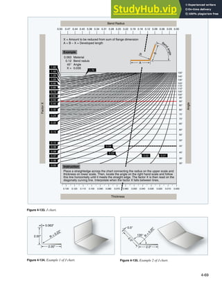
![4-70
UPPER JAW
BED
LOWER JAW
BENDING
LEAF
NOSE RADIUS
BAR
Each of these nose radius shims
is 0.063 inch thick, which gives
radius choices of 1/8", 3/16", and 1/4"
This radius shim builds radius
to precisely 1/16"R
Figure 4-138. Nose radius shims may be used when the brake radius bar is smaller than required.
Figure 4-137. Interchangeable brake radius bars.
Figure 4-136. Brake radius nosepiece adjustment.
smaller than required for the part, it is necessary to bend
some nose radius shims. [Figure 4-138]
If the radius is so small that it tends to crack annealed
aluminum, mild steel is a good choice of material.
Experimentation with a small piece of scrap material is
necessary to manufacture a thickness that increases the radius
to precisely 1
⁄16-inch or 1
⁄8-inch. Use radius and illet gauges
to check this dimension. From this point on, each additional
shim is added to the radius before it. [Figure 4-139]
Example: If the original nose was 1
⁄16-inch and a piece of .063-
inch material (1
⁄16-inch) was bent around it, the new outside
radius is 1
⁄8-inch. If another .063-inch layer (1
⁄16-inch) is added,
it is now a 3
⁄16-inch radius. If a piece of .032-inch (1
⁄32-inch)
instead of .063-inch material (1
⁄16-inch) is bent around the
1
⁄8-inch radius, a 5
⁄32-inch radius results.
Step 2: Adjusting Clamping Pressure
The next step is setting clamping pressure. Slide a piece of
the material with the same thickness as the part to be bent
under the brake radius piece. Pull the clamping lever toward
the operator to test the pressure. This is an over center type
clamp and, when properly set, will not feel springy or spongy
when pulled to its fully clamped position. The operator must
be able to pull this lever over center with a irm pull and have
it bump its limiting stops. On some brakes, this adjustment
has to be made on both sides of the brake.](https://image.slidesharecdn.com/aircraftmetalstructuralrepair-230807175411-df5215b3/85/Aircraft-Metal-Structural-Repair-pdf-70-320.jpg)
![4-71
Pull forward to clamp (no sponginess
felt when evenly set on BOTH sides)
Note: Bending leaf counterbalance omitted for clarity
Limiting stop
Nut to adjust clamping pressure
Lifting nut
Radius shims
Material to be bent
Figure 4-139. General brake overview including radius shims.
Clamping pressure
adjustment nut
Brake nose gap
adjustment knob
Figure 4-140. Adjust clamping pressure with the clamping pressure
nut.
Place test strips on the table 3-inch from each end and one
in the center between the bed and the clamp, adjust clamp
pressure until it is tight enough to prevent the work pieces
from slipping while bending. The clamping pressure can
be adjusted with the clamping pressure nut. [Figure 4-140]
Step 3: Adjusting the Nose Gap
Adjust the nose gap by turning the large brake nose gap
adjustment knobs at the rear of the upper jaw to achieve
its proper alignment. [Figure 4-140] The perfect setting
is obtained when the bending leaf is held up to the angle
of the inished bend and there is one material thickness
between the bending leaf and the nose radius piece. Using
a piece of material the thickness of the part to be bent as a
feeler gauge can help achieve a high degree of accuracy.
[Figures 4-141 and 4-142] It is essential this nose gap be
perfect, even across the length of the part to be bent. Check
by clamping two test strips between the bed and the clamp
3-inch from each end of the brake. [Figure 4-143] Bend 90°
[Figure 4-144], remove test strips, and place one on top of
the other; they should match. [Figure 4-145] If they do not
match, adjust the end with the sharper bend back slightly.
Folding a Box
A box can be formed the same way as the U-channel
described on in the previous paragraphs, but when a sheet
metal part has intersecting bend radii, it is necessary to
remove material to make room for the material contained in](https://image.slidesharecdn.com/aircraftmetalstructuralrepair-230807175411-df5215b3/85/Aircraft-Metal-Structural-Repair-pdf-71-320.jpg)
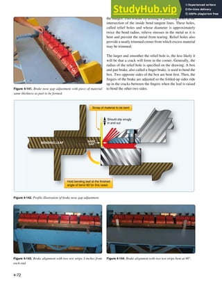
![4-73
Figure 4-145. Brake alignment by comparing test strips.
2"
Flat
Flat Flat
Area of bend (BA)
Area
of
bend
(BA)
1"
2"
Bend relief radius
Intersection of
inside bend
tangent lines
Figure 4-146. Relief hole location.
11⁄16
1 11⁄16
11
⁄
16
7⁄16
7
⁄
16
2 13⁄16
2
1
2
13
⁄
16
Notice overlapping mold lines (by 1 MG)
R = 0.250 (1⁄4)
T = 0.063 (1⁄16)
SB = 0.313 (5⁄16)
BA = 0.437 (7⁄16)
MG = 0.191 (3⁄16)
Normal trim
tangent to radius
If necessary for
flanges to touch
If 5⁄16 R is required,
punch 5⁄8 hole
Figure 4-147. Relief hole layout.
The size of relief holes varies with thickness of the material.
They should be no less than 1
⁄8-inch in diameter for aluminum
alloy sheet stock up to and including 0.064-inch thick, or
3
⁄160-inch in diameter for stock ranging from 0.072-inch
to 0.128-inch thickness. The most common method of
determining the diameter of a relief hole is to use the radius
of bend for this dimension, provided it is not less than the
minimum allowance (1
⁄8-inch).
Relief Hole Location
Relief holes must touch the intersection of the inside bend
tangent lines. To allow for possible error in bending, make
the relief holes extend 1
⁄32-inch to 1
⁄16-inch behind the inside
bend tangent lines. It is good practice to use the intersection
of these lines as the center for the holes. The line on the inside
of the curve is cut at an angle toward the relief holes to allow
for the stretching of the inside lange.
The positioning of the relief hole is important. [Figure 4-146]
It should be located so its outer perimeter touches the
intersection of the inside bend tangent lines. This keeps any
material from interfering with the bend allowance area of the
other bend. If these bend allowance areas intersected with
each other, there would be substantial compressive stresses
that would accumulate in that corner while bending. This
could cause the part to crack while bending.
Layout Method
Lay out the basic part using traditional layout procedures.
This determines the width of the lats and the bend allowance.
It is the intersection of the inside bend tangent lines that index
the bend relief hole position. Bisect these intersected lines
and move outward the distance of the radius of the hole on
this line. This is the center of the hole. Drill at this point and
inish by trimming off the remainder of the corner material.
The trim out is often tangent to the radius and perpendicular
to the edge. [Figure 4-147] This leaves an open corner. If the
corner must be closed, or a slightly longer lange is necessary,
then trim out accordingly. If the corner is to be welded, it
is necessary to have touching langes at the corners. The](https://image.slidesharecdn.com/aircraftmetalstructuralrepair-230807175411-df5215b3/85/Aircraft-Metal-Structural-Repair-pdf-73-320.jpg)
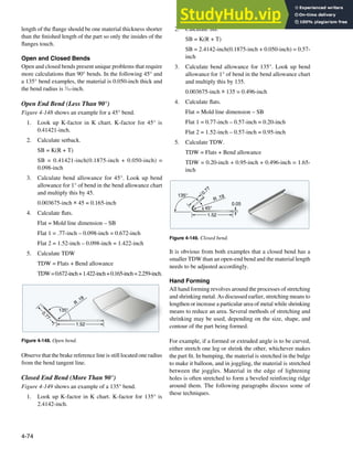
![4-75
Figure 4-150. V-block forming.
Straight Line Bends
The cornice brake and bar folder are ordinarily used to make
straight bends. Whenever such machines are not available,
comparatively short sections can be bent by hand with the
aid of wooden or metal bending blocks.
After a blank has been laid out and cut to size, clamp it along
the bend line between two wooden forming blocks held in
a vise. The wooden forming blocks should have one edge
rounded as needed for the desired radius of bend. It should
also be curved slightly beyond 90° to allow for spring-back.
Bend the metal that protrudes beyond the bending block to
the desired angle by tapping lightly with a rubber, plastic,
or rawhide mallet. Start tapping at one end and work back
and forth along the edge to make a gradual and even bend.
Continue this process until the protruding metal is bent to the
desired angle against the forming block. Allow for spring-
back by driving the material slightly farther than the actual
bend. If a large amount of metal extends beyond the forming
blocks, maintain hand pressure against the protruding sheet
to prevent it from bouncing. Remove any irregularities by
holding a straight block of hardwood edgewise against the
bend and striking it with heavy blows of a mallet or hammer.
If the amount of metal protruding beyond the bending blocks
is small, make the entire bend by using the hardwood block
and hammer.
Formed or Extruded Angles
Both formed and extruded types of angles can be curved (not
bent sharply) by stretching or shrinking either of the langes.
Curving by stretching one lange is usually preferred since
the process requires only a V-block and a mallet and is easily
accomplished.
Stretching With V-Block Method
In the stretching method, place the lange to be stretched in
the groove of the V-block. [Figure 4-150] (If the lange is
to be shrunk, place the lange across the V-block.) Using a
round, soft-faced mallet, strike the lange directly over the
V portion with light, even blows while gradually forcing it
downward into the V.
Beginat one end of the lange and form the curve graduallyand
evenly by moving the strip slowly back and forth, distributing
the hammer blows at equal spaces on the lange. Hold the
strip irmly to keep it from bouncing when hammered. An
overly heavy blow buckles the metal, so keep moving the
lange across the V-block, but always lightly strike the spot
directly above the V.
Lay out a full-sized, accurate pattern on a sheet of paper or
plywood and periodically check the accuracy of the curve.
Comparing the angle with the pattern determines exactly
how the curve is progressing and just where it needs to be
increased or decreased. It is better to get the curve to conform
roughly to the desired shape before attempting to inish any
one portion, because the inishing or smoothing of the angle
may cause some other portion of the angle to change shape.
If any part of the angle strip is curved too much, reduce the
curve by reversing the angle strip on the V-block, placing the
bottom lange up, and striking it with light blows of the mallet.
Try to form the curve with a minimum amount of hammering,
for excessive hammering work-hardens the metal. Work-
hardening can be recognized by a lack of bending response or
by springiness in the metal. It can be recognized very readily
by an experienced worker. In some cases, the part may have
to be annealed during the curving operation. If so, be sure
to heat treat the part again before installing it on the aircraft.
Shrinking With V-Block and Shrinking Block Methods
Curving an extruded or formed angle strip by shrinking may
be accomplished by either the previously discussed V-block
method or the shrinking block method. While the V-block
is more satisfactory because it is faster, easier, and affects
the metal less, good results can be obtained by the shrinking
block method.
In the V-block method, place one lange of the angle strip
lat on the V-block with the other lange extending upward.
Using the process outlined in the stretching paragraphs, begin
at one end of the angle strip and work back and forth making
light blows. Strike the edge of the lange at a slight angle to
keep the vertical lange from bending outward.](https://image.slidesharecdn.com/aircraftmetalstructuralrepair-230807175411-df5215b3/85/Aircraft-Metal-Structural-Repair-pdf-75-320.jpg)
![4-76
Figure 4-151. Crimping a metal flange in order to form a curve.
Occasionally, check the curve for accuracy with the pattern.
If a sharp curve is made, the angle (cross section of the
formed angle) closes slightly. To avoid such closing of the
angle, clamp the angle strip to a hardwood board with the
hammered lange facing upward using small C-clamps. The
jaws of the C-clamps should be covered with masking tape.
If the angle has already closed, bring the lange back to the
correct angle with a few blows of a mallet or with the aid
of a small hardwood block. If any portion of the angle strip
is curved too much, reduce it by reversing the angle on the
V-block and hammering with a suitable mallet, as explained
in the previous paragraph on stretching. After obtaining the
proper curve, smooth the entire angle by planishing with a
soft-faced mallet.
If the curve in a formed angle is to be quite sharp or if the
langes of the angle are rather broad, the shrinking block
method is generally used. In this process, crimp the lange
that is to form the inside of the curve.
When making a crimp, hold the crimping pliers so that the
jaws are about 1
⁄8-inch apart. By rotating the wrist back and
forth, bring the upper jaw of the pliers into contact with the
lange, irst on one side and then on the other side of the
lower jaw. Complete the crimp by working a raised portion
into the lange, gradually increasing the twisting motion of
the pliers. Do not make the crimp too large because it will
be dificult to work out. The size of the crimp depends upon
the thickness and softness of the material, but usually about
1
⁄4-inch is suficient. Place several crimps spaced evenly along
the desired curve with enough space left between each crimp
so that jaws of the shrinking block can easily be attached.
After completing the crimping, place the crimped lange in
the shrinking block so that one crimp at a time is located
between the jaws. [Figure 4-151] Flatten each crimp with
light blows of a soft-faced mallet, starting at the apex (the
closed end) of the crimp and gradually working toward the
edge of the lange. Check the curve of the angle with the
pattern periodically during the forming process and again
after all the crimps have been worked out. If it is necessary to
increase the curve, add more crimps and repeat the process.
Space the additional crimps between the original ones so that
the metal does not become unduly work hardened at any one
point. If the curve needs to be increased or decreased slightly
at any point, use the V-block.
After obtaining the desired curve, planish the angle strip over
a stake or a wooden form.
Flanged Angles
The forming process for the following two langed angles
is slightly more complicated than the previously discussed
angles because the bend is shorter (not gradually curved) and
necessitates shrinking or stretching in a small or concentrated
area. If the lange is to point toward the inside of the bend, the
material must be shrunk. If it is to point toward the outside,
it must be stretched.
Shrinking
In forming a langed angle by shrinking, use wooden forming
blocks similar to those shown in Figure 4-152 and proceed
as follows:
1. Cut the metal to size, allowing for trimming after
forming. Determine the bend allowance for a 90° bend
and round the edge of the forming block accordingly.
2. Clamp the material in the form blocks as shown in
Figure 4-96, and bend the exposed lange against the
block. After bending, tap the blocks slightly. This
induces a setting process in the bend.
3. Using a soft-faced shrinking mallet, start hammering
near the center and work the lange down gradually
toward both ends. The lange tends to buckle at the
bend because the material is made to occupy less
space. Work the material into several small buckles
instead of one large one and work each buckle
out gradually by hammering lightly and gradually
compressing the material in each buckle. The use of
a small hardwood wedge block aids in working out
the buckles. [Figure 4-153]
4. Planish the lange after it is lattened against the form
block and remove small irregularities. If the form
blocks are made of hardwood, use a metal planishing
hammer. If the forms are made of metal, use a soft-
faced mallet. Trim the excess material away and ile
and polish.](https://image.slidesharecdn.com/aircraftmetalstructuralrepair-230807175411-df5215b3/85/Aircraft-Metal-Structural-Repair-pdf-76-320.jpg)
![4-77
Form blocks
Hardwood wedge block
Figure 4-152. Forming a flanged angle using forming blocks.
Figure 4-153. Shrinking.
Figure 4-154. Stretching a flanged angle.
Stretching
To form a langed angle by stretching, use the same forming
blocks, wooden wedge block, and mallet as used in the
shrinking process and proceed as follows:
1. Cut the material to size (allowing for trim), determine
bend allowance for a 90° bend, and round off the edge
of the block to conform to the desired radius of bend.
2. Clamp the material in the form blocks. [Figure 4-154]
3. Using a soft-faced stretching mallet, start hammering
near the ends and work the lange down smoothly
and gradually to prevent cracking and splitting.
Planish the flange and angle as described in the
previous procedure, and trim and smooth the edges,
if necessary.
Curved Flanged Parts
Curved langed parts are usually hand formed with a concave
lange, the inside edge, and a convex lange, the outside edge.
The concave flange is formed by stretching, while the
convex flange is formed by shrinking. Such parts are
shaped with the aid of hardwood or metal forming blocks.
[Figure 4-155] These blocks are made in pairs and are
designed specifically for the shape of the area being
formed. These blocks are made in pairs similar to those
used for straight angle bends and are identiied in the same
manner. They differ in that they are made speciically for
the particular part to be formed, they it each other exactly,
and they conform to the actual dimensions and contour of
the inished article.
The forming blocks may be equipped with small aligning
pins to help line up the blocks and to hold the metal in place
or they may be held together by C-clamps or a vise. They
also may be held together with bolts by drilling through form](https://image.slidesharecdn.com/aircraftmetalstructuralrepair-230807175411-df5215b3/85/Aircraft-Metal-Structural-Repair-pdf-77-320.jpg)
![4-78
Flange
Holes
Figure 4-156. Plain nose rib.
Figure 4-157. Nose rib with relief holes.
Figure 4-155. Forming blocks.
Crimps
Figure 4-158. Nose rib with crimps.
blocks and the metal, provided the holes do not affect the
strength of the inished part. The edges of the forming block
are rounded to give the correct radius of bend to the part, and
are undercut approximately 5° to allow for spring-back of the
metal. This undercut is especially important if the material
is hard or if the bend must be accurate.
The nose rib offers a good example of forming a curved
lange because it incorporates both stretching and shrinking
(by crimping). They usually have a concave lange, the
inside edge, and a convex lange, the outside edge. Note
the various types of forming represented in the following
igures. In the plain nose rib, only one large convex lange
is used. [Figure 4-156] Because of the great distance around
the part and the likelihood of buckles in forming, it is rather
dificult to form. The lange and the beaded (raised ridge
on sheet metal used to stiffen the piece) portion of this rib
provide suficient strength to make this a good type to use.
In Figure 4-157, the concave lange is dificult to form, but
the outside lange is broken up into smaller sections by relief
holes. In Figure 4-158, note that crimps are placed at equally
spaced intervals to absorb material and cause curving, while
also giving strength to the part.
In Figure 4-159, the nose rib is formed by crimping, beading,
putting in relief holes, and using a formed angle riveted on
each end. The beads and the formed angles supply strength
to the part. The basic steps in forming a curved lange follow:
[Figures 4-160 and 161]
1. Cut the material to size, allowing about 1
⁄4-inch excess
material for trim and drill holes for alignment pins.
2. Remove all burrs (jagged edges). This reduces the
possibility of the material cracking at the edges during
the forming process.
3. Locate and drill holes for alignment pins.](https://image.slidesharecdn.com/aircraftmetalstructuralrepair-230807175411-df5215b3/85/Aircraft-Metal-Structural-Repair-pdf-78-320.jpg)
![4-79
Figure 4-159. Nose rib using a combination of forms.
Figure 4-160. Forming a concave flange.
45°
Figure 4-161. Forming a convex flange.
4. Place the material between the form blocks and
clamp blocks tightly in a vise to prevent the material
from moving or shifting. Clamp the work as closely
as possible to the particular area being hammered to
prevent strain on the form blocks and to keep the metal
from slipping.
Concave Surfaces
Bend the lange on the concave curve irst. This practice
may keep the lange from splitting open or cracking when
the metal is stretched. Should this occur, a new piece must
be made. Using a plastic or rawhide mallet with a smooth,
slightly rounded face, start hammering at the extreme ends
of the part and continue toward the center of the bend. This
procedure permits some of the metal at the ends of the part
to be worked into the center of the curve where it is needed.
Continue hammering until the metal is gradually worked
down over the entire lange, lush with the form block. After
the lange is formed, trim off the excess material and check
the part for accuracy. [Figure 4-160]
Convex Surfaces
Convex surfaces are formed by shrinking the material over
a form block. [Figure 4-161] Using a wooden or plastic
shrinking mallet and a backup or wedge block, start at the
center of the curve and work toward both ends. Hammer the
lange down over the form, striking the metal with glancing
blows at an angle of approximately 45° and with a motion
that tends to pull the part away from the radius of the form
block. Stretch the metal around the radius bend and remove
the buckles gradually by hammering on a wedge block. Use](https://image.slidesharecdn.com/aircraftmetalstructuralrepair-230807175411-df5215b3/85/Aircraft-Metal-Structural-Repair-pdf-79-320.jpg)
![4-80
1
2
2
3
3
4
4
1
1
2
3
1
Templates for workingthe form block
Form block
Holddown plate
Finished part
Figure 4-162. Form block bumping.
the backup block to keep the edge of the lange as nearly
perpendicular to the form block as possible. The backup block
also lessens the possibility of buckles, splits, or cracks. Finally,
trim the langes of excess metal, planish, remove burrs, round
the corners (if any), and check the part for accuracy.
Forming by Bumping
As discussed earlier, bumping involves stretching the sheet
metal by bumping it into a form and making it balloon.
[Figure 4-162] Bumping can be done on a form block or
female die, or on a sandbag.
Either method requires only one form: a wooden block, a lead
die, or a sandbag. The blister, or streamlined cover plate, is
an example of a part made by the form block or die method
of bumping. Wing illets are an example of parts that are
usually formed by bumping on a sandbag.
Form Block or Die
The wooden block or lead die designed for form block
bumping must have the same dimensions and contour as the
outside of the blister. To provide enough bucking weight
and bearing surface for fastening the metal, the block or die
should be at least one inch larger in all dimensions than the
form requires.
Follow these procedures to create a form block:
1. Hollow the block out with tools, such as saws, chisels,
gouges, iles, and rasps.
2. Smooth and inish the block with sandpaper. The inside
of the form must be as smooth as possible, because the
slightest irregularity shows up on the inished part.
3. Prepare several templates (patterns of the cross-
section), as shown in Figure 4-162 so that the form
can be checked for accuracy.
4. Shape the contour of the form at points 1, 2, and 3.
5. Shape the areas between the template checkpoints to
conform the remaining contour to template 4. Shaping
of the form block requires particular care because
the more nearly accurate it is, the less time it takes to
produce a smooth, inished part.
After the form is prepared and checked, perform the bumping
as follows:
1. Cut a metal blank to size allowing an extra 1
⁄2 to 1-inch
to permit drawing.
2. Apply a thin coat of light oil to the block and the
aluminum to prevent galling (scraping on rough spots).
3. Clamp the material between the block and steel plate.
Ensure it is irmly supported yet it can slip a little
toward the inside of the form.
4. Clamp the bumping block in a bench vise. Use a soft-
faced rubber mallet, or a hardwood drive block with
a suitable mallet, to start the bumping near the edges
of the form.
5. Work the material down gradually from the edges
with light blows of the mallet. Remember, the purpose
of bumping is to work the material into shape by](https://image.slidesharecdn.com/aircraftmetalstructuralrepair-230807175411-df5215b3/85/Aircraft-Metal-Structural-Repair-pdf-80-320.jpg)
![4-81
Figure 4-163. Sandbag bumping.
stretching rather than forcing it into the form with
heavy blows. Always start bumping near the edge of
the form. Never start near the center of the blister.
6. Before removing the work from the form, smooth it
as much as possible by rubbing it with the rounded
end of either a maple block or a stretching mallet.
7. Remove the blister from the bumping block and trim
to size.
Sandbag Bumping
Sandbag bumping is one of the most dificult methods of
hand forming sheet metal because there is no exact forming
block to guide the operation. [Figure 4-163] In this method,
a depression is made into the sandbag to take the shape of
the hammered portion of the metal. The depression or pit has
a tendency to shift from the hammering, which necessitates
periodic readjustment during the bumping process. The
degree of shifting depends largely on the contour or shape
of the piece being formed, and whether glancing blows must
be struck to stretch, draw, or shrink the metal. When forming
by this method, prepare a contour template or some sort of
a pattern to serve as a working guide and to ensure accuracy
of the inished part. Make the pattern from ordinary kraft or
similar paper, folding it over the part to be duplicated. Cut the
paper cover at the points where it would have to be stretched
to it, and attach additional pieces of paper with masking tape
to cover the exposed portions. After completely covering the
part, trim the pattern to exact size.
Open the pattern and spread it out on the metal from which
the part is to be formed. Although the pattern does not lie lat,
it gives a fairly accurate idea of the approximate shape of the
metal to be cut, and the pieced-in sections indicate where the
metal is to be stretched. When the pattern has been placed on
the material, outline the part and the portions to be stretched
using a felt-tipped pen. Add at least 1-inch of excess metal
when cutting the material to size. Trim off the excess metal
after bumping the part into shape.
If the part to be formed is radially symmetrical, it is fairly
easy to shape since a simple contour template can be used as a
working guide. The procedure for bumping sheet metal parts
on a sandbag follows certain basic steps that can be applied
to any part, regardless of its contour or shape.
1. Lay out and cut the contour template to serve as a
working guide and to ensure accuracy of the inished
part. (This can be made of sheet metal, medium to
heavy cardboard, kraft paper, or thin plywood.)
2. Determine the amount of metal needed, lay it out, and
cut it to size, allowing at least 1
⁄2-inch in excess.
3. Place a sandbag on a solid foundation capable of
supporting heavy blows and make a pit in the bag with
a smooth-faced mallet. Analyze the part to determine
the correct radius the pit should have for the forming
operation. The pit changes shape with the hammering
it receives and must be readjusted accordingly.
4. Select a soft round-faced or bell-shaped mallet with
a contour slightly smaller than the contour desired on
the sheet metal part. Hold one edge of the metal in the
left hand and place the portion to be bumped near the
edge of the pit on the sandbag. Strike the metal with
light glancing blows.
5. Continue bumping toward the center, revolving the
metal, and working gradually inward until the desired
shape is obtained. Shape the entire part as a unit.
6. Check the part often for accuracy of shape during the
bumping process by applying the template. If wrinkles
form, work them out before they become too large.
7. Remove small dents and hammer marks with a suitable
stake and planishing hammer or with a hand dolly and
planishing hammer.
8. Finally, after bumping is completed, use a pair of
dividers to mark around the outside of the object. Trim
the edge and ile it smooth. Clean and polish the part.
Joggling
A joggle, often found at the intersection of stringers and
formers, is the offset formed on a part to allow clearance for
a sheet or another mating part. Use of the joggle maintains
the smooth surface of a joint or splice. The amount of offset
is usually small; therefore, the depth of the joggle is generally
speciied in thousandths of an inch. The thickness of the
material to be cleared governs the depth of the joggle. In
determining the necessary length of the joggle, allow an extra
1
⁄16-inch to give enough added clearance to assure a it between
the joggled, overlapped part. The distance between the two
bends of a joggle is called the allowance. This dimension is
normally called out on the drawing. However, a general rule of
thumb for iguring allowance is four times the thickness of the](https://image.slidesharecdn.com/aircraftmetalstructuralrepair-230807175411-df5215b3/85/Aircraft-Metal-Structural-Repair-pdf-81-320.jpg)
![4-82
Clamping device
Material being joggled
Joggle block
Joggle block
Wooden mallet
Bulge caused by forming joggle
STEP 1
Place material between joggle blocks and
squeeze in a vice or other clamping device.
STEP 2
Turn joggle blocks over in vice and flatten
bulge with wooden mallet.
Figure 4-164. Forming joggle using joggle blocks.
displacement of lat sheets. For 90° angles, it must be slightly
more due to the stress built up at the radius while joggling.
For extrusions, the allowance can be as much as 12 times the
material thickness, so, it is important to follow the drawing.
There are a number of different methods of forming
joggles. For example, if the joggle is to be made
on a straight flange or flat piece of metal, it can be
formed on a cornice break. To form the joggle, use the
following procedure:
1. Lay out the boundary lines of the joggle where the
bends are to occur on the sheet.
2. Insert the sheet in the brake and bend the metal up
approximately 20° to 30°.
3. Release the brake and remove the part.
4. Turn the part over and clamp it in the brake at the
second bend line.
5. Bend the part up until the correct height of the joggle
is attained.
6. Remove the part from the brake and check the joggle
for correct dimensions and clearance.
When a joggle is necessary on a curved part or a curved
lange, forming blocks or dies made of hardwood, steel,
or aluminum alloy may be used. The forming procedure
consists of placing the part to be joggled between the two
joggle blocks and squeezing them in a vice or some other
suitable clamping device. After the joggle is formed, the
joggle blocks are turned over in the vice and the bulge on
the opposite lange is lattened with a wooden or rawhide
mallet. [Figure 4-164]
Since hardwood is easily worked, dies made of hardwood are
satisfactory when the die is to be used only a few times. If
a number of similar joggles are to be produced, use steel or
aluminum alloy dies. Dies of aluminum alloy are preferred
since they are easier to fabricate than those of steel and wear
about as long. These dies are suficiently soft and resilient
to permit forming aluminum alloy parts on them without
marring, and nicks and scratches are easily removed from
their surfaces.
When using joggling dies for the irst time, test them for
accuracy on a piece of waste stock to avoid the possibility
of ruining already fabricated parts. Always keep the surfaces
of the blocks free from dirt, ilings, and the like, so that the
work is not marred. [Figure 4-165]
Lightening Holes
Lightening holes are cut in rib sections, fuselage frames, and
other structural parts to decrease weight. To avoid weakening
the member by removal of the material, langes are often
pressed around the holes to strengthen the area from which
the material was removed.
Lightening holes should never be cut in any structural part
unless authorized. The size of the lightening hole and the
width of the lange formed around the hole are determined by
design speciications. Margins of safety are considered in the
speciications so that the weight of the part can be decreased
and still retain the necessary strength. Lightening holes may
be cut with a hole saw, a punch, or a ly cutter. The edges
are iled smooth to prevent them from cracking or tearing.](https://image.slidesharecdn.com/aircraftmetalstructuralrepair-230807175411-df5215b3/85/Aircraft-Metal-Structural-Repair-pdf-82-320.jpg)
![4-83
Figure 4-165. Samples of joggled metal.
Figure 4-166. Lightening hole die set.
500
300
150
80–30
29–U
3/8
Drill Size Maximum RPM
Figure 4-167. Drill size and speed for drilling Inconel.
Flanging Lightening Holes
Form the lange by using a langing die, or hardwood or
metal form blocks. Flanging dies consist of two matching
parts: a female and a male die. For langing soft metal, dies
can be of hardwood, such as maple. For hard metal or for
more permanent use, they should be made of steel. The pilot
guide should be the same size as the hole to be langed, and
the shoulder should be the same width and angle as the
desired lange.
When langing lightening holes, place the material between
the mating parts of the die and form it by hammering or
squeezing the dies together in a vise or in an arbor press (a
small hand operated press). The dies work more smoothly
if they are coated with light machine oil. [Figure 4-166]
Working Stainless Steel
Corrosion-resistant-steel (CRES) sheet is used on some
parts of the aircraft when high strength is required. CRES
causes magnesium, aluminum, or cadmium to corrode when
it touches these metals. To isolate CRES from magnesium
and aluminum, apply a inish that gives protection between
their mating surfaces. It is important to use a bend radius
that is larger than the recommended minimum bend radius
to prevent cracking of the material in the bend area.
When working with stainless steel, make sure that the metal
does not become unduly scratched or marred. Also, take
special precautions when shearing, punching, or drilling this
metal. It takes about twice as much pressure to shear or punch
stainless steel as it does mild steel. Keep the shear or punch
and die adjusted very closely. Too much clearance permits
the metal to be drawn over the edge of the die and causes it
to become work hardened, resulting in excessive strain on
the machine. When drilling stainless steel, use an HSS drill
bit ground to an included angle of 135°. Keep the drill speed
about one-half that required for drilling mild steel, but never
exceed 750 rpm. Keep a uniform pressure on the drill so the
feed is constant at all times. Drill the material on a backing
plate, such as cast iron, which is hard enough to permit the
drill bit to cut completely through the stock without pushing
the metal away from the drill point. Spot the drill bit before
turning on the power and also make sure that pressure is
exerted when the power is turned on.
Working Inconel® Alloys 625 and 718
Inconel® refers to a family of nickel-chromium-iron super
alloys typically used in high-temperature applications.
Corrosion resistance and the ability to stay strong in high
temperatures led to the frequent use of these Inconel® alloys
in aircraft powerplant structures. Inconel® alloys 625 and 718
can be cold formed by standard procedures used for steel
and stainless steel.
Normal drilling into Inconel® alloys can break drill bits
sooner and cause damage to the edge of the hole when the
drill bit goes through the metal. If a hand drill is used to
drill Inconel® alloys 625 and 718, select a 135° cobalt drill
bit. When hand drilling, push hard on the drill, but stay at
a constant chip rate. For example, with a No. 30 hole, push
the drill with approximately 50 pounds of force. Use the
maximum drill rpm as illustrated in Figure 4-167. A cutting
luid is not necessary when hand drilling.
The following drilling procedures are recommended:
• Drill pilot holes in loose repair parts with power feed
equipment before preassembling them.
• Preassemble the repair parts and drill the pilot holes
in the mating structure.](https://image.slidesharecdn.com/aircraftmetalstructuralrepair-230807175411-df5215b3/85/Aircraft-Metal-Structural-Repair-pdf-83-320.jpg)
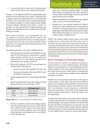
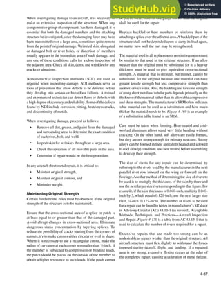
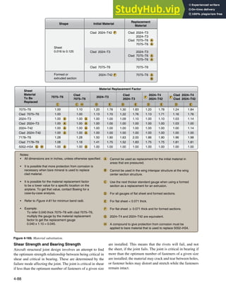
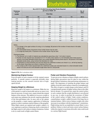
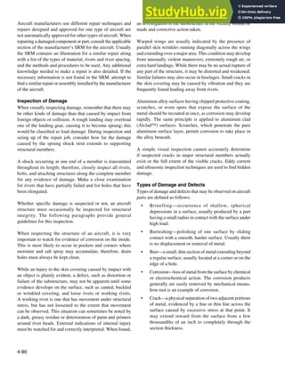
![4-91
Crack
Crack
Stop-drill cracks
Figure 4-171. Repair of cracks by stop-drilling.
• Cut—loss of metal, usually to an appreciable depth
over a relatively long and narrow area, by mechanical
means, as would occur with the use of a saw blade,
chisel, or sharp-edged stone striking a glancing blow.
• Dent—indentation in a metal surface produced by an
object striking with force. The surface surrounding
the indentation is usually slightly upset.
• Erosion—loss of metal from the surface by
mechanical action of foreign objects, such as grit or
ine sand. The eroded area is rough and may be lined
in the direction in which the foreign material moved
relative to the surface.
• Chattering—breakdown or deterioration of metal
surface by vibratory or chattering action. Although
chattering may give the general appearance of metal
loss or surface cracking, usually, neither has occurred.
• Galling—breakdown (or build-up) of metal surfaces
due to excessive friction between two parts having
relative motion. Particles of the softer metal are torn
loose and welded to the harder metal.
• Gouge—groove in, or breakdown of, a metal surface
from contact with foreign material under heavy
pressure. Usually it indicates metal loss but may be
largely the displacement of material.
• Inclusion—presence of foreign or extraneous material
wholly within a portion of metal. Such material is
introduced during the manufacture of rod, bar or
tubing by rolling or forging.
• Nick—local break or notch on an edge. Usually it
involves the displacement of metal rather than loss.
• Pitting—sharp, localized breakdown (small, deep
cavity) of metal surface, usually with deined edges.
• Scratch—slight tear or break in metal surface from
light, momentary contact by foreign material.
• Score—deeper (than scratch) tear or break in metal
surface from contact under pressure. May show
discoloration from temperature produced by friction.
• Stain—a change in color, locally causing a noticeably
different appearance from the surrounding area.
• Upsetting—a displacement of material beyond the
normal contour or surface (a local bulge or bump).
Usually it indicates no metal loss.
Classiication of Damage
Damages may be grouped into four general classes. In many
cases, the availabilities of repair materials and time are the
most important factors in determining if a part should be
repaired or replaced.
Negligible Damage
Negligible damage consists of visually apparent, surface
damage that do not affect the structural integrity of the
component involved. Negligible damage may be left as is or
may be corrected by a simple procedure without restricting
light. In both cases, some corrective action must be taken to
keep the damage from spreading. Negligible or minor damage
areas must be inspected frequently to ensure the damage does
not spread. Permissible limits for negligible damage vary
for different components of different aircraft and should be
carefully researched on an individual basis. Failure to ensure
that damages within the speciied limit of negligible damage
may result in insuficient structural strength of the affected
support member for critical light conditions.
Small dents, scratches, cracks, and holes that can be repaired
by smoothing, sanding, stop drilling, or hammering out, or
otherwise repaired without the use of additional materials,
fall in this classiication. [Figure 4-171]
Damage Repairable by Patching
Damage repairable by patching is any damage exceeding
negligible damage limits that can be repaired by installing
splice members to bridge the damaged portion of a structural
part. The splice members are designed to span the damaged
areas and to overlap the existing undamaged surrounding
structure. The splice or patch material used in internal riveted
and bolted repairs is normally the same type of material as
the damaged part, but one gauge heavier. In a patch repair,
iller plates of the same gauge and type of material as that in
the damaged component may be used for bearing purposes or
to return the damaged part to its original contour. Structural
fasteners are applied to members and the surrounding](https://image.slidesharecdn.com/aircraftmetalstructuralrepair-230807175411-df5215b3/85/Aircraft-Metal-Structural-Repair-pdf-91-320.jpg)
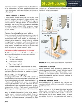
![4-93
Figure 4-173. Smoking rivet.
several consecutive rivets and are probably tipped in the same
direction. If heads that appear to be tipped are not in groups
and are not tipped in the same direction, tipping may have
occurred during some previous installation.
Inspect rivets that are known to have been critically loaded,
but that show no visible distortion, by drilling off the head and
carefully punching out the shank. If upon examination, the
shank appears joggled and the holes in the sheet misaligned,
the rivet has failed in shear. In that case, determine what
is causing the stress and take necessary corrective action.
Countersunk rivets that show head slippage within the
countersink or dimple, indicating either sheet bearing failure
or rivet shear failure, must be replaced.
Joggles in removed rivet shanks indicate partial shear failure.
Replace these rivets with the next larger size. Also, if the
rivet holes show elongation, replace the rivets with the next
larger size. Sheet failures, such as tearouts, cracks between
rivets, and the like, usually indicate damaged rivets, and the
complete repair of the joint may require replacement of the
rivets with the next larger size.
The presence of a black residue around the rivets is not an
indication of looseness, but it is an indication of movement
(fretting). The residue, which is aluminum oxide, is formed
by a small amount of relative motion between the rivet and
the adjacent surface. This is called fretting corrosion, or
smoking, because the aluminum dust quickly forms a dark,
dirty looking trail, like a smoke trail. Sometimes, the thinning
of the moving pieces can propagate a crack. If a rivet is
suspected of being defective, this residue may be removed
with a general purpose abrasive hand pad, such as those
manufactured by Scotch Brite™, and the surface inspected
for signs of pitting or cracking. Although the condition
indicates the component is under signiicant stress, it does
not necessarily precipitate cracking. [Figure 4-173]
Airframe cracking is not necessarily caused by defective
rivets. It is common practice in the industry to size rivet
patterns assuming one or more of the rivets is not effective.
This means that a loose rivet would not necessarily overload
adjacent rivets to the point of cracking.
Rivet head cracking are acceptable under the following
conditions:
• The depth of the crack is less than 1
⁄8 of the shank
diameter.
• The width of the crack is less than 1
⁄16 of the shank
diameter.
• The length of the crack is conined to an area
on the head within a circle having a maximum
diameter of 11
⁄4 times the shank diameter.
• Cracks should not intersect, which creates the
potential for the loss of a portion of a head.
Inspection for Corrosion
Corrosion is the gradual deterioration of metal due to a
chemical or electrochemical reaction with its environment.
The reaction can be triggered by the atmosphere, moisture,
or other agents. When inspecting the structure of an aircraft,
it is important to watch for evidence of corrosion on both the
outside and inside. Corrosion on the inside is most likely to
occur in pockets and corners where moisture and salt spray
may accumulate; therefore, drain holes must always be kept
clean. Also inspect the surrounding members for evidence
of corrosion.
Damage Removal
To prepare a damaged area for repair:
1. Remove all distorted skin and structure in
damaged area.
2. Remove damaged material so that the edges of the
completed repair match existing structure and aircraft
lines.
3. Round all square corners.
4. Smooth out any abrasions and/or dents.
5. Remove and incorporate into the new repair any
previous repairs joining the area of the new repair.
Repair Material Selection
The repair material must duplicate the strength of the original
structure. If an alloy weaker than the original material has
to be used, a heavier gauge must be used to give equivalent
cross-sectional strength. A lighter gauge material should not
be used even when using a stronger alloy.
Repair Parts Layout
All new sections fabricated for repairing or replacing
damaged parts in a given aircraft should be carefully laid
out to the dimensions listed in the applicable aircraft manual
before itting the parts into the structure.](https://image.slidesharecdn.com/aircraftmetalstructuralrepair-230807175411-df5215b3/85/Aircraft-Metal-Structural-Repair-pdf-93-320.jpg)
![4-94
Figure 4-174. FAA Form 337.
Rivet Selection
Normally, the rivet size and material should be the same as
the original rivets in the part being repaired. If a rivet hole has
been enlarged or deformed, the next larger size rivet must be
used after reworking the hole. When this is done, the proper
edge distance for the larger rivet must be maintained. Where
access to the inside of the structure is impossible and blind
rivets must be used in making the repair, always consult the
applicable aircraft maintenance manual for the recommended
type, size, spacing, and number of rivets needed to replace
either the original installed rivets or those that are required
for the type of repair being performed.
Rivet Spacing and Edge Distance
The rivet pattern for a repair must conform to instructions
in the applicable aircraft manual. The existing rivet pattern
is used whenever possible.
Corrosion Treatment
Prior to assembly of repair or replacement parts, make certain
that all existing corrosion has been removed in the area and
that the parts are properly insulated one from the other.
Approval of Repair
Once the need for an aircraft repair has been established, Title
14 of the Code of Federal Regulations (14 CFR) deines the
approval process. 14 CFR part 43, section 43.13(a) states that
each person performing maintenance, alteration, or preventive
maintenance on an aircraft, engine, propeller, or appliance
shall use the methods, techniques, and practices prescribed in
the current manufacturer’s maintenance manual or instructions
for continued airworthiness prepared by its manufacturer, or
other methods, techniques, or practices acceptable to the
Administrator. AC 43.13-1 contains methods, techniques, and
practices acceptable to the Administrator for the inspection
and repair of nonpressurized areas of civil aircraft, only when
there are no manufacturer repair or maintenance instructions.
This data generally pertains to minor repairs. The repairs
identiied in this AC may only be used as a basis for FAA
approval for major repairs. The repair data may also be used
as approved data, and the AC chapter, page, and paragraph
listed in block 8 of FAA Form 337 when:
a. The user has determined that it is appropriate to the
product being repaired;
b. It is directly applicable to the repair being made; and
c. It is not contrary to manufacturer’s data.
Engineering support from the aircraft manufacturer is
required for repair techniques and methods that are not
described in the aircraft maintenance manual or SRM.
FAA Form 337, Major Repair and Alteration, must be
completed for repairs to the following parts of an airframe and
repairs of the following types involving the strengthening,
reinforcing, splicing, and manufacturing of primary structural
members or their replacement, when replacement is by
fabrication, such as riveting or welding. [Figure 4-174]
• Box beams
• Monocoque or semimonocoque wings or
control surfaces
• Wing stringers or chord members
• Spars
• Spar langes](https://image.slidesharecdn.com/aircraftmetalstructuralrepair-230807175411-df5215b3/85/Aircraft-Metal-Structural-Repair-pdf-94-320.jpg)
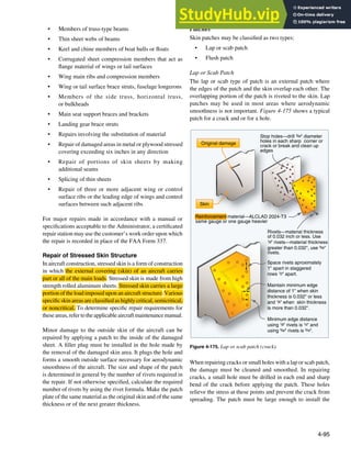
![4-96
Neutral axis
5°
Rivet hole
Edge distance
Neutral axis
Edge distance
T
1/2 T
45°
Figure 4-176. Lap patch edge preparation.
Damage
Doubler
Filler
r
Doubler riveted in place
Filler riveted in place
Damaged area cut
to a smooth rectangle
with corner radil
Figure 4-177. Typical flush patch repair.
required number of rivets. It may be cut circular, square,
or rectangular. If it is cut square or rectangular, the corners
are rounded to a radius no smaller than 1
⁄4-inch. The edges
must be chamfered to an angle of 45° for 1
⁄2 the thickness
of the material, and bent down 5° over the edge distance
to seal the edges. This reduces the chance that the repair is
affected by the airlow over it. These dimensions are shown
in Figure 4-176.
Flush Patch
A lush patch is a iller patch that is lush to the skin when
applied it is supported by and riveted to a reinforcement
plate which is, in turn, riveted to the inside of the skin.
Figure 4-177 shows a typical lush patch repair. The doubler
is inserted through the opening and rotated until it slides in
place under the skin. The iller must be of the same gauge
and material as the original skin. The doubler should be of
material one gauge heavier than the skin.
Open and Closed Skin Area Repair
The factors that determine the methods to be used in
skin repair are accessibility to the damaged area and the
instructions found in the aircraft maintenance manual. The
skin on most areas of an aircraft is inaccessible for making
the repair from the inside and is known as closed skin.
Skin that is accessible from both sides is called open skin.
Usually, repairs to open skin can be made in the conventional
manner using standard rivets, but in repairing closed skin,
some type of special fastener must be used. The exact type
to be used depends on the type of repair being made and the
recommendations of the aircraft manufacturer.
Design of a Patch for a Nonpressurized Area
Damage to the aircraft skin in a non-pressurized area can be
repaired by a lush patch if a smooth skin surface is required or
by an external patch in noncritical areas. [Figure 4-178] The
irst step is to remove the damage. Cut the damage to a round,
oval, or rectangular shape. Round all corners of a rectangular
patch to a minimum radius of 0.5-inch. The minimum edge
distance used is 2 times the diameter and the rivet spacing
is typically between 4-6 times the diameter. The size of the
doubler depends on the edge distance and rivet spacing. The
doubler material is of the same material as the damaged skin,
but of one thickness greater than the damaged skin. The size
of the doubler depends on the edge distance and rivet spacing.
The insert is made of the same material and thickness as the
damaged skin. The size and type of rivets should be the same
as rivets used for similar joints on the aircraft. The SRM
indicates what size and type of rivets to use.](https://image.slidesharecdn.com/aircraftmetalstructuralrepair-230807175411-df5215b3/85/Aircraft-Metal-Structural-Repair-pdf-96-320.jpg)
![4-97
Insertion
Doubler
Skin
Insertion
Patch
Skin
Skin
Skin
Doubler
1/4 inch deep dent
Insertion patch method
Cover patch method
P
E
E
Figure 4-178. Repair patch for a non-pressurized area.
Typical Repairs for Aircraft Structures
This section describes typical repairs of the major structural
parts of an airplane. When repairing a damaged component
or part, consult the applicable section of the manufacturer’s
SRM for the aircraft. Normally, a similar repair is illustrated,
and the types of material, rivets, and rivet spacing and the
methods and procedures to be used are listed. Any additional
knowledge needed to make a repair is also detailed. If the
necessary information is not found in the SRM, attempt to
ind a similar repair or assembly installed by the manufacturer
of the aircraft.
Floats
To maintain the loat in an airworthy condition, periodic and
frequent inspections should be made because of the rapidity
of corrosion on metal parts, particularly when the aircraft is
operated in salt water. Inspection of loats and hulls involves
examination for damage due to corrosion, collision with
other objects, hard landings, and other conditions that may
lead to failure.
NOTE: Blind rivets should not be used on loats or amphibian
hulls below the water line.
Sheet-metal floats should be repaired using approved
practices; however, the seams between sections of sheet
metal should be waterproofed with suitable fabric and sealing
compound. A loat that has undergone hull repairs should be
tested by illing it with water and allowing it to stand for at
least 24 hours to see if any leaks develop. [Figure 4-179]
Corrugated Skin Repair
Some of the light controls of smaller general aviation aircraft
have beads in their skin panels. The beads give some stiffness
to the thin skin panels. The beads for the repair patch can be
formed with a rotary former or press brake. [Figure 4-180]
Replacement of a Panel
Damage to metal aircraft skin that exceeds repairable limits
requires replacement of the entire panel. [Figure 4-181] A
panel must also be replaced when there are too many previous
repairs in a given section or area.
In aircraft construction, a panel is any single sheet of metal
covering. A panel section is the part of a panel between
adjacent stringers and bulk heads. Where a section of skin
is damaged to such an extent that it is impossible to install
a standard skin repair, a special type of repair is necessary.
The particular type of repair required depends on whether the
damage is repairable outside the member, inside the member,
or to the edges of the panel.
Outside the Member
For damage that, after being trimmed, has 81
⁄2 rivet
diameters or more of material, extend the patch to include
the manufacturer’s row of rivets and add an extra row inside
the members.
Inside the Member
For damage that, after being trimmed, has less than 81
⁄2
manufacturer’s rivet diameters of material inside the
members, use a patch that extends over the members and an
extra row of rivets along the outside of the members.
Edges of the Panel
For damage that extends to the edge of a panel, use
only one row of rivets along the panel edge, unless the
manufacturer used more than one row. The repair procedure
for the other edges of the damage follows the previously
explained methods.](https://image.slidesharecdn.com/aircraftmetalstructuralrepair-230807175411-df5215b3/85/Aircraft-Metal-Structural-Repair-pdf-97-320.jpg)
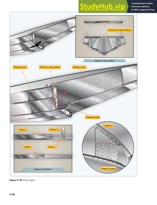
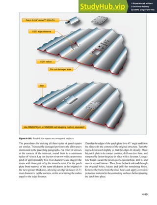
![4-100
Repair seam same as strongest
parallel adjacent seam.
Repair seam same as strongest
parallel adjacent seam. Use original
holes and add as needed.
Additional Rivets Trimmed hole
radiused corners
3/16" 5/32" 1/8"
Figure 4-181. Replacement of an entire panel.
Repair of Lightening Holes
As discussed earlier, lightening holes are cut in rib sections,
fuselage frames, and other structural parts to reduce the
weight of the part. The holes are langed to make the web
stiffer. Cracks can develop around langed lightening holes,
and these cracks need to be repaired with a repair plate.
The damaged area (crack) needs to be stop drilled or the
damage must be removed. The repair plate is made of the
same material and thickness as the damaged part. Rivets are
the same as in surrounding structure and the minimum edge
distance is 2 times the diameter and spacing is between four
to six times the diameter. Figure 4-182 illustrates a typical
lightening hole repair.
Repairs to a Pressurized Area
The skin of aircraft that are pressurized during light is highly
stressed. The pressurization cycles apply loads to the skin,
and the repairs to this type of structure requires more rivets
than a repair to a nonpressurized skin. [Figure 4-183]
1. Remove the damaged skin section.
2. Radius all corners to 0.5-inch.
3. Fabricate a doubler of the same type of material as,
but of one size greater thickness than, the skin. The
size of the doubler depends on the number of rows,
edge distance, and rivets spacing.
4. Fabricate an insert of the same material and same
thickness as the damaged skin. The skin to insert
clearance is typically 0.015-inch to 0.035-inch.
5. Drill the holes through the doubler, insertion, and
original skin.
6. Spread a thin layer of sealant on the doubler and secure
the doubler to the skin with Clecos.
7. Use the same type of fastener as in the surrounding
area, and install the doubler to the skin and the
insertion to the doubler. Dip all fasteners in the sealant
before installation.
Stringer Repair
The fuselage stringers extend from the nose of the aircraft
to the tail, and the wing stringers extend from the fuselage
to the wing tip. Surface control stringers usually extend the](https://image.slidesharecdn.com/aircraftmetalstructuralrepair-230807175411-df5215b3/85/Aircraft-Metal-Structural-Repair-pdf-100-320.jpg)
![4-101
A
A
View -
A A
Repair for crack on lightening hole flange
Stop drill ends of crack use #40 drill
Patch is same material and thickness as web
Repair for crack between lightening holes
Figure 4-182. Repair of lightening holes.
length of the control surface. The skin of the fuselage, wing,
or control surface is riveted to stringers.
Stringers may be damaged by vibration, corrosion, or
collision. Because stringers are made in many different
shapes, repair procedures differ. The repair may require the
use of preformed or extruded repair material, or it may require
material formed by the airframe technician. Some repairs may
need both kinds of repair material. When repairing a stringer,
irst determine the extent of the damage and remove the rivets
from the surrounding area. [Figure 4-184] Then, remove the
damaged area by using a hacksaw, keyhole saw, drill, or ile.
In most cases, a stringer repair requires the use of insert and
splice angle. When locating the splice angle on the stringer
during repair, be sure to consult the applicable structural
repair manual for the repair piece’s position. Some stringers
are repaired by placing the splice angle on the inside, whereas
others are repaired by placing it on the outside.
Extrusions and preformed materials are commonly used to
repair angles and insertions or illers. If repair angles and
illers must be formed from lat sheet stock, use the brake.
It may be necessary to use bend allowance and sight lines
when making the layout and bends for these formed parts.
For repairs to curved stringers, make the repair parts so that
they it the original contour.
Figure 4-185 shows a stringer repair by patching. This repair
is permissible when the damage does not exceed two-thirds
of the width of one leg and is not more than 12-inch long.
Damage exceeding these limits can be repaired by one of the
following methods.
Figure 4-186 illustrates repair by insertion where damage
exceeds two-thirds of the width of one leg and after a portion
of the stringer is removed. Figure 4-187 shows repair by
insertion when the damage affects only one stringer and](https://image.slidesharecdn.com/aircraftmetalstructuralrepair-230807175411-df5215b3/85/Aircraft-Metal-Structural-Repair-pdf-101-320.jpg)
![4-102
Insertion
Doubler
Skin
Insertion
Skin
Doubler
P
E
Sealer
Removed damage
Figure 4-183. Pressurized skin repair.
0.35"
0.35"
0.50"
-
A A
0.58"
0.58"
0.10" rad.
A
A
A
A
A
0.064" 245-T4 Alclad
TM
strip
Use AN470 or AN456 AD3 rivets
Stringer CS-14 and CS-15
0.04" 245-T4 Alclad
TM
If damage has been cut away from center section of stringer length,
both ends of new portion must be attached as shown below.
3.35"
3.35"
0.90"
0.90"
0.40"
0.90"
0.90" 0.20"
Original structure
Repair parts
Repair parts in
cross section
Figure 4-184. Stringer repair.
exceeds 12-inch in length. Figure 4-188 illustrates repair
by an insertion when damage affects more than one stringer.
Former or Bulkhead Repair
Bulkheads are the oval-shaped members of the fuselage
that give form to and maintain the shape of the structure.
Bulkheads or formers are often called forming rings,
body frames, circumferential rings, belt frames, and other
similar names. They are designed to carry concentrated
stressed loads.
There are various types of bulkheads. The most common type
is a curved channel formed from sheet stock with stiffeners
added. Others have a web made from sheet stock with
extruded angles riveted in place as stiffeners and langes.
Most of these members are made from aluminum alloy.
Corrosion-resistant steel formers are used in areas that are
exposed to high temperatures.
Bulkhead damages are classiied in the same manner as
other damages. Speciications for each type of damage are
established by the manufacturer and speciic information is
given in the maintenance manual or SRM for the aircraft.
Bulkheads are identiied with station numbers that are very
helpful in locating repair information. Figure 4-189 is an
example of a typical repair for a former, frame section, or
bulkhead repair.
1. Stop drill the crack ends with a No. 40 size drill.
2. Fabricate a doubler of the same material but one size
thicker than the part being repaired. The doubler
should be of a size large enough to accommodate 1
⁄8-
inch rivet holes spaced one inch apart, with a minimum
edge distance of 0.30-inch and 0.50-inch spacing
between staggered rows. [Figure 4-190]
3. Attach the doubler to the part with clamps and
drill holes.
4. Install rivets.
Most repairs to bulkheads are made from lat sheet stock if
spare parts are not available. When fabricating the repair from
lat sheet, remember the substitute material must provide](https://image.slidesharecdn.com/aircraftmetalstructuralrepair-230807175411-df5215b3/85/Aircraft-Metal-Structural-Repair-pdf-102-320.jpg)
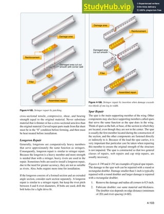
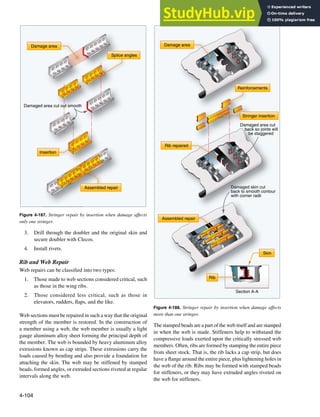
![4-105
Crack
Stop drill #40 drill hole
Stop drill #40 drill hole
Crack
Doubler
Doubler
Bulkhead
Radius to rest in bulkhead
Bulkhead
1
.
5
"
m
i
n
i
m
u
m
1
.
5
"
m
i
n
i
m
u
m
OR
Radius to rest in bulkhead
Figure 4-189. Bulkhead repair.
Most damages involve two or more members, but only one
member may be damaged and need repairing. Generally,
if the web is damaged, cleaning out the damaged area and
installing a patch plate are all that is required.
The patch plate should be of suficient size to ensure room for
at least two rows of rivets around the perimeter of the damage
that includes proper edge distance, pitch, and transverse pitch
for the rivets. The patch plate should be of material having the
same thickness and composition as the original member. If
any forming is necessary when making the patch plate, such
as itting the contour of a lightening hole, use material in the
“0” condition and then heat treat it after forming.
Damage to ribs and webs, that require a repair larger than a
simple plate, probably needs a patch plate, splice plates, or
angles and an insertion. [Figure 4-192]
Leading Edge Repair
The leading edge is the front section of a wing, stabilizer, or
other airfoil. The purpose of the leading edge is to streamline
the forward section of the wings or control surfaces to
ensure effective airlow. The space within the leading edge
is sometimes used to store fuel. This space may also house
extra equipment, such as landing lights, plumbing lines, or
thermal anti-icing systems.
The construction of the leading edge section varies with the
type of aircraft. Generally, it consists of cap strips, nose ribs,
stringers, and skin. The cap strips are the main lengthwise
extrusions, and they stiffen the leading edges and furnish a
base for the nose ribs and skin. They also fasten the leading
edge to the front spar.
The nose ribs are stamped from aluminum alloy sheet or
machined parts. These ribs are U-shaped and may have
their web sections stiffened. Regardless of their design, their
purpose is to give contour to the leading edge. Stiffeners
are used to stiffen the leading edge and supply a base for
fastening the nose skin. When fastening the nose skin, use
only lush rivets.
Leading edges constructed with thermal anti-icing systems
consist of two layers of skin separated by a thin air space. The
inner skin, sometimes corrugated for strength, is perforated
to conduct the hot air to the nose skin for anti-icing purposes.
Damage can be caused by contact with other objects, namely,
pebbles, birds, and hail. However, the major cause of damage
is carelessness while the aircraft is on the ground.
A damaged leading edge usually involves several structural
parts. FOD probably involves the nose skin, nose ribs,
stringers, and possibly the cap strip. Damage involving all
of these members necessitates installing an access door to
make the repair possible. First, the damaged area has to be
removed and repair procedures established. The repair needs
insertions and splice pieces. If the damage is serious enough,
it may require repair of the cap strip and stringer, a new nose
rib, and a skin panel. When repairing a leading edge, follow
the procedures prescribed in the appropriate repair manual
for this type of repair. [Figure 4-193] Repairs to leading
edges are more dificult to accomplish than repairs to lat
and straight structures because the repair parts need to be
formed to it the existing structure.
Trailing Edge Repair
A trailing edge is the rearmost part of an airfoil found on
the wings, ailerons, rudders, elevators, and stabilizers. It is](https://image.slidesharecdn.com/aircraftmetalstructuralrepair-230807175411-df5215b3/85/Aircraft-Metal-Structural-Repair-pdf-105-320.jpg)
![4-106
A
A
2
1
3
Spar chord
Web
Fillet seal (typical) Seal heads (typical)
Make a laying surface seal refer to SRM 51-20-05
Web
3
0.050
0.070
Gap (typical)
2
1
2D
minumum
(typical)
Damage cutout 0.50R minimum all corners
AFT
B
B
Note: Use this repair at the
inboard end of the spar
when the damage is near
the upper or lower chord.
Figure 4-190. Wing spar repair.
usually a metal strip that forms the shape of the edge by tying
the ends of a rib section together and joining the upper and
lower skins. Trailing edges are not structural members, but
they are considered to be highly stressed in all cases.
Damage to a trailing edge may be limited to one point or
extended over the entire length between two or more rib
sections. Besides damage resulting from collision and
careless handling, corrosion damage is often present. Trailing
edges are particularly subject to corrosion because moisture
collects or is trapped in them.
Thoroughly inspect the damaged area before starting repairs,
and determine the extent of damage, the type of repair
required, and the manner in which the repair should be
performed. When making trailing edge repairs, remember
that the repaired area must have the same contour and be
made of material with the same composition and temper as
the original section. The repair must also be made to retain
the design characteristics of the airfoil. [Figure 4-194]](https://image.slidesharecdn.com/aircraftmetalstructuralrepair-230807175411-df5215b3/85/Aircraft-Metal-Structural-Repair-pdf-106-320.jpg)
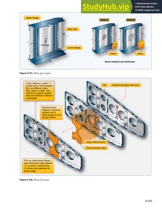
![4-108
0.63" to 0.94" spacing
two evenly staggered
rows at 0.55" minimum
pitch
Nose rib
Repair plate
0.50 R minimum (typical)
Rib access hole in nose beam
Nose beam
Doubler
0.35" minimum
edge margin
Figure 4-193. Leading edge repair.
Specialized Repairs
Figures 4-195 through 4-199 are examples of repairs for
various structural members. Speciic dimensions are not
included since the illustrations are intended to present the
basic design philosophy of general repairs rather than be
used as repair guidelines for actual structures. Remember to
consult the SRM for speciic aircraft to obtain the maximum
allowable damage that may be repaired and the suggested
method for accomplishing the repair.
Inspection Openings
If it is permitted by the applicable aircraft maintenance
manual, installation of a lush access door for inspection
purposes sometimes makes it easier to repair the internal
structure as well as damage to the skin in certain areas. This
installation consists of a doubler and a stressed cover plate.
A single row of nut plates is riveted to the doubler, and the
doubler is riveted to the skin with two staggered rows of
rivets. [Figure 4-200] The cover plate is then attached to the
doubler with machine screws.](https://image.slidesharecdn.com/aircraftmetalstructuralrepair-230807175411-df5215b3/85/Aircraft-Metal-Structural-Repair-pdf-108-320.jpg)
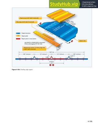
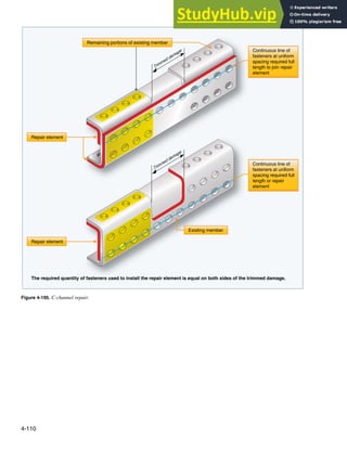
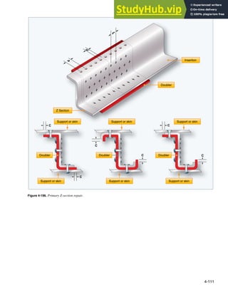
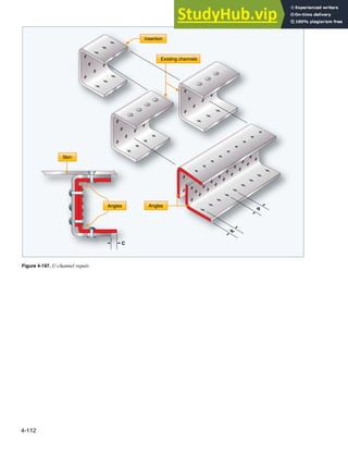
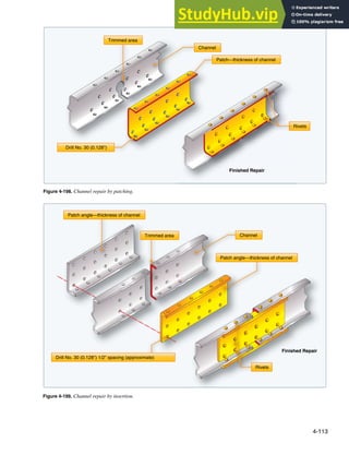
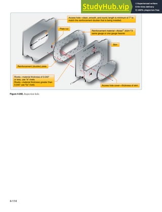

This document discusses aircraft metal structural repair. It explains that aircraft structural integrity must be maintained through continuous repair and maintenance, as improper repairs can pose safety risks. The design of metal structural repairs is complicated by the need for aircraft to be as light as possible while still safely carrying all loads. Different types of stresses act on aircraft structures, including tension, compression, shear, bearing, and bending stresses. Proper repair requires duplicating the original structure's strength, material, and dimensions to safely transfer stresses across the repair.


