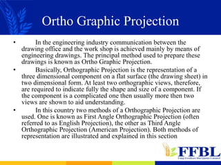
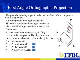
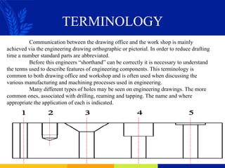
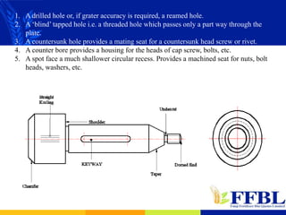
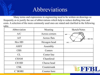
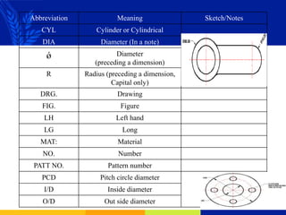
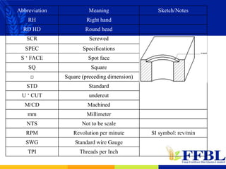
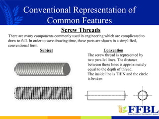
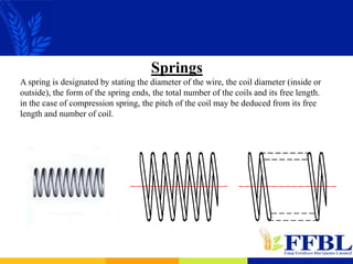
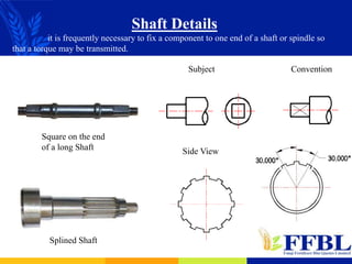
SlideShare a Scribd company logo
BASIC ENGINEERING
DRAWING
Prepared By: Syed Basharat Ali
Basic Engineering Drawing Contents
 Ortho Graphic Projection
 Lines
 Sectioning
 Terminology
 Abbreviations
 Conventional Representation Of Common Features
 Pictorial Drawing
 Dimensioning
 Limits And Fits
 Threads
 Assembly Drawing
Ortho Graphic Projection
• In the engineering industry communication between the
drawing office and the work shop is achieved mainly by means of
engineering drawings. The principal method used to prepare these
drawings is known as Ortho Graphic Projection.
• Basically, Orthographic Projection is the representation of a
three dimensional component on a flat surface (the drawing sheet) in
two dimensional form. At least two orthographic views, therefore,
are required to indicate fully the shape and size of a component. If
the component is a complicated one then usually more then two
views are shown to aid understanding.
• In this country two methods of a Orthographic Projection are
used. One is known as First Angle Orthographic Projection (often
referred to as English Projection), the other as Third Angle
Orthographic Projection (American Projection). Both methods of
representation are illustrated and explained in this section
First Angle Orthographic Projection
The pictorial drawing opposite indicates the shape of the component
with a single view.
An orthographic drawing indicates the
Shape of a component by using a number of
views each looking at a different face of the
Component.
At least two views are necessary to fully
represent the component. Usually , however,
three views are shown in order to clarify internal
And external detail.
 A Front View (F)
 A Plan View (P)
 A side View (L&R)
Front View
 The front view or front elevation represents what is seen when
looking at the front of the component in the direction of arrow F.
Plan View
 A plan view represent what is seen when looking at the top of the
component in the direction of arrow P.
Side View
 The side view or side elevation represents what is seen when
looking at the side of the component in the direction of either arrow
R or arrow L. These arrows are at 90° to both arrow F and arrow P.
View looking in
direction of arrow R.
Right- Hand
Side View (R)
View looking in
direction of arrow L.
Left- Hand
Side View (L)
In First Angle Ortho Graphic Projection The Front View is Above the Top view.
The Right-hand side view is on the Left-hand side of the front view.
The left hand side view is on the Right-hand side of the front view.
Third Angle Orthographic Projection
When representing a three dimensional component in Third Angle
Orthographic Projection, the basic views are exactly the same as those
shown when using First Angle Orthographic Projection . The
difference between First Angle and Third Angle
is in the positioning of the views relative to
each other. In Third Angle Orthographic
Projection the individual views are placed on
the drawing sheet in projection with each other
as shown:
Point For Third Angle
Orthographic Projection
 The plan is always projected ABOVE the front view.
 The right-hand side view is shown on the RIGHT-Hand side of the
front view.
 The left-hand side view is shown on the LEFT-Hand side of the
front view.
A Comparison Of First And Third
Angle Ortho Graphic Projection
• The plan is BLOW the front view.
• The Right-hand side view is on the Left-
hand side of the front view.
• The left hand side view is on the
Right-hand side of the front view.
• The plan is ABOVE the front view.
• The right-hand side view is on the Right-
hand side of the front view.
• The left-hand side view is on the Left-hand
side of the front view.
Kind Of Lines
Kinds Of Lines
Line Group
(Intensity measured in mm)
Typical application
1,2 0,8 0,5 0,3
Solid
1,2 0,8 0,5 0,3 Visible edge of parts; contours
0,4 0,3 0,2 0,1
Dimension lines, extension lines, hatching lines, cross section
lines, reference line, surface line, contour lines of adjacent
parts.
Broken (dashed)
0,6 0,4 0,3 0,2
Invisible edges
Alternate long
dashes with dots 1,2 0,8 0,5 0,3
Lines indicating section planes.
Center lines, Circular pitches, index circle, finished parts
down machine allowance, ultimate lever position.
Common Lines Used In Engineering
Drawings
Sample Drawing
Sectioning
Drawings of the outside of sample components are often
sufficient to convey all the information necessary to make the
component. More complicated components, however may
require sectional views to clarify internals details.
A sectional view is obtained when one imagines the
component to be cut through a chosen section plane often on
a center line.
If the vee-block is cut on section plane C-C as shown
the resulting sectional view projected from the plan
replaces the usual front view of the block.
Sectional Front View
looking on cutting
plane C-C
End View
Sectional views are drawn only when it is necessary to explain the construction of a
complex object or assembly. Some of the examples used in the next few slides have been
chosen to illustrate the rules of sectioning although in practice, as in the case of the vee-block
drawn above a sectional view may not have been necessary.
The draftsman has to decide how a component or assembly should be sectioned in
order to provide the fullest possible information. The recommendations of BS 308 enable
him to do this in a way that is understood by all engineers.
Rules Of Sectioning
 A sectioned object is shown by lines drawn preferably at 45°.
Thin lines touch the outline. Size of sectioned part determines line
spacing preferably not less than 4 mm.
 If two adjacent parts are sectioned , the section lines are drawn
in opposite directions. Lines are staggered where the parts are in
contact.
 Where more then two parts of an assembly are to be sectioned,
the lines cannot all be opposite. Sectional lines are closer together
on the third area usually the smallest
 The sectional view of a symmetrical object is obtained when the section plane
cuts through the obvious centre line. Hatching may be omitted if the meaning is
clear without it.
 If an object is NOT symmetrical the section plane chosen should be clearly
stated.
Sectioning Exceptions
There are a number of a features and parts which are not normally sectioned even though
they may lie in the section plane. A good way to accept these exceptions to be general rule is
to imagine how complicated the drawing would look if they were sectioned. They are
sectioned, however, when they lie across the section plane.
Staggered Section Planes
Section C-C
Revolved
Section D-D
Revolved
Section A-A
Realigned
Each Part of the section plane is swung to the vertical
before projecting to the sectional End view. By using the
convention the draftsman avoids using too many auxiliary
views. A staggered section plane should only be used when
there is a resulting gain in clarity.
TERMINOLOGY
Communication between the drawing office and the work shop is mainly
achieved via the engineering drawing orthographic or pictorial. In order to reduce drafting
time a number standard parts are abbreviated.
Before this engineers “shorthand” can be correctly it is necessary to understand
the terms used to describe features of engineering components. This terminology is
common to both drawing office and workshop and is often used when discussing the
various manufacturing and machining processes used in engineering.
Many different types of holes may be seen on engineering drawings. The more
common ones, associated with drilling, reaming and tapping. The name and where
appropriate the application of each is indicated.
1. A drilled hole or, if grater accuracy is required, a reamed hole.
2. A ‘blind’ tapped hole i.e. a threaded hole which passes only a part way through the
plate.
3. A countersunk hole provides a mating seat for a countersunk head screw or rivet.
4. A counter bore provides a housing for the heads of cap screw, bolts, etc.
5. A spot face a much shallower circular recess. Provides a machined seat for nuts, bolt
heads, washers, etc.
Abbreviations
Many terms and expressions in engineering need to be written on drawings so
frequently as to justify the use of abbreviations which help to reduce drafting time and
costs. A selection of the more commonly used ones are stated and clarified in the following
table.
Abbreviation Meaning Sketch/Notes
A/C Across corners
A/F Across flats
Hex HD Hexagon head
ASSY Assembly
CRS Centers
CL Center line
CHAM Chamfered
CH HD Cheese head
CSK Countersunk
C’ BORE Counter bore
Abbreviation Meaning Sketch/Notes
CYL Cylinder or Cylindrical
DIA Diameter (In a note)
ǿ Diameter
(preceding a dimension)
R Radius (preceding a dimension,
Capital only)
DRG. Drawing
FIG. Figure
LH Left hand
LG Long
MAT: Material
NO. Number
PATT NO. Pattern number
PCD Pitch circle diameter
I/D Inside diameter
O/D Out side diameter
Abbreviation Meaning Sketch/Notes
RH Right hand
RD HD Round head
SCR Screwed
SPEC Specifications
S ‘ FACE Spot face
SQ Square
□ Square (preceding dimension)
STD Standard
U ‘ CUT undercut
M/CD Machined
mm Millimeter
NTS Not to be scale
RPM Revolution per minute SI symbol: rev/min
SWG Standard wire Gauge
TPI Threads per Inch
Conventional Representation of
Common Features
Screw Threads
There are many components commonly used in engineering which are complicated to
draw to full. In order to save drawing time, these parts are shown in a simplified,
conventional form.
Subject Convention
The screw thread is represented by
two parallel lines. The distance
between these lines is approximately
equal to the depth of thread.
The inside line is THIN and the circle
is broken
Springs
A spring is designated by stating the diameter of the wire, the coil diameter (inside or
outside), the form of the spring ends, the total number of the coils and its free length.
in the case of compression spring, the pitch of the coil may be deduced from its free
length and number of coil.
Shaft Details
it is frequently necessary to fix a component to one end of a shaft or spindle so
that a torque may be transmitted.
Convention
Subject
Side View
Square on the end
of a long Shaft
Splined Shaft
Knurling
Knurling is a common method of providing a roughened to aid tightening or
slackening of a screw by hand. This is formed by pressing special rollers against the
surface of the component whist it revolves in lathe.
Diamond Knurl on a machine screw head
Straight Knurl on a circuit terminal
Subject Convention
Long Components
There are occasions when bars, shafts, spindles or tubes may be too long to be
drawn to a reasonable scale. In such cases the elevation may be interrupted .
Subject Convention
Hollow Shaft “OR” Tube
Rectangular Bar
Circular Shaft “OR” Spindle
Multiple Holes
When a large number of holes of equal diameter are equally spaced around a
diameter or a line, only one hole need be drawn in full with the reminder marked with a
short center line.
That circle is
called the pitch
circle diameter
or PCD
Gears
Before gears be drawn a great deal of background knowledge about their
nomenclature and construction must be acquired.
Subject Convention
Side view
of gear
wheel is
in section
Spur
Gear
Worm
And
Wheel
A good example of a how a complex component maybe drawn relatively
simply is the bevel gear. The assembly shown blow is of a pair of gear of equal size, the
direction of motion being changed through an angle 90°. In the arrangement he gears
are often referred to mitre wheel.
The gares ma be of differing sizes of course and the angle between the shaft
may be other then 90°. In this letter case, the side view of the gear assembly would
have to show one gear as then ellipse.
Pictorial Drawing
A component may be represented graphically in various ways. An
Orthographic Drawing, for example, requiring a minimum of two views to
fully communicate the size and the shape of a component, is used in
engineering mainly to convey manufacturing instruction from the designer
to the craftsman. On the other hand a well executed Pictorial Drawing
adequately representing all but the most complicated components using
one view only, is used mainly as an aid to visualization of the shape of a
component rather then for communication detailed instruction for
manufacture.
A pictorial drawing, generally, is a quickly produced approximately scaled
representation of a component a “picture” rather then an accurately scaled
line drawing.
There are many different types of pictorial representation. Two of the most
commonly used ones are known as Isometric Drawing
and Oblique Drawing.
Isometric
All receding lines are
drawn at 30°
Oblique
An oblique pictorial drawing presents with the component with one of its faces as a true
shape. This shape is drawn on the front face of the oblique box as shown below.
The longest face is usually drawn on the front of the oblique box with receding lines
between ½ and ¾ full size.
Methods Of Construction Of
Oblique Drawing
There are many variations in angle, length of receding lines, and directions
from which a component may be viewed in order to produce an oblique drawing as can
be seen by examples on the previous slide. Different oblique drawings of the same
component may each provide the details required.
 The receding lines may be drawn at any angle to the horizontal but an
angle of 30, 45, 60 is proffered as lines can be drawn with set squares.
 Receding lines may be any proportion of heir true length. A good
pictorial representation is obtained if lengths from ½ to ¾ actual length is used.
Dimensioning
A number of the basic rules of dimensioning can be explained by reference to the above
drawing of a thin plate.
The sides marked A and B are known as DATUM faces. They are used as reference
edges from which dimensions are drawn. Datum's may or may not be machined. Even if
they are not machined it is good practice to choose reference edges in order to simplify
the layout of dimensions.
1. Dimension Line: Thin full lines placed outside the component where possible
and spaced well away from the out lines. The longer dimension lines are placed
outside shorter ones.
2. Projection Lines: Thin full lines which extend from the view to provide a
boundary for the dimension line. Drawn at 90° to the out line.
3. Arrowheads: Drawn with sharp strokes which must touch the extension lines.
4. A Leader line is a thin full line which is drawn from a note, a dimension or, in this
case, a “balloon” and terminates in an arrowhead or a dot.
5. Relatively small gap.
6. Relatively short tail.
7. Crossing extensions lines usually a break to ensure clarity.
8. Dimension placed above the dimension line. This is preferred to the alternative
method of placing the dimension in a gap in the line. Avoid using both methods on
the same drawing if possible.
9. Dimension placed so that it may be read from bottom or right hand side of the
drawing sheet.
Arrangement Of Dimensions
Dimensions should be placed so that they may be read from either the bottom or
right-hand side of a drawing, for example:
Various methods of dimensioning narrow spaces or width are shown above.
Dimensioning Circles
1. The way a circle is dimensioned the dimension always refers to the diameter and
NOT the radius.
2. A circle is never dimensioned on a center line.
3. The conventional symbol for diameter is ∅.
The leader line must be
drawn in line with the
center of the circle.
In the example it is
preferable to dimension
the side view even tough
the cylindrical shape is
not apparent. Dimension
in this view, however,
must
always be preceded by
symbol ∅.
Dimensioning Radii
A radius should be dimensioned by a dimension line which passes through, or is in line
with, the center of the arc.
The dimension line should have one arrowhead which should be placed at the point of
contact with the arc. The abbreviation R should always precede the dimension.
Dimensioning Angles
Angles are Expressed in:
1. Degrees e.g. 90°
2. Degrees and minutes e.g. 27 ° 30’
The placing of the angular dimension depends on the position of the angle in
relation to the bottom and/or the right-hand side of the drawing sheet and
the size of the angle.
Dimensioning Chamfers
45° chamfer should be specified by one of the methods below:
Location Dimensions
The features can be located from a machined surface or center line. Such s surface or line
is known as DATUM.
Examples on pervious slides have been shown components and features may be
dimensioned when size is the main consideration.
Spigot located from
two reference edges (
R).
Both holes located from two
reference edges ( R).
Both holes located from two
reference edges ( R) then
hole B related to hole A.
The simple bearing bracket casting on the left
shows both size and location dimensions.
Reference surface are marked with machining
symbol:-
This is placed so that it may be read from the
right of the sheet.
It is preferable to place the symbol on the
appropriate projection line rather than as show
on the left.
No symbol is required where the machine is
specified i.e. in the case of the drilled holes, the
reamed holes and the spot-face.
The location dimension are those show with letter L
and size dimensions by a letter S. Some of the size dimensions are less accurate then other
e.g. the thickness of the rib is fixed during the casting process whistle the 11 mm diameter
holes is accurately reamed. The 20 mm diameter hole located by the dimension from the
machined base to the center line of the hole.
Threads
A screw thread, often shortened to thread, is a helical structure used to convert
between rotational and linear movement or force. A screw thread is a ridge wrapped
around a cylinder or cone in the form of a helix, with the former being called a straight
thread and the latter called a tapered thread. A screw thread is the essential feature of the
screw as a simple machine and also as a fastener.
 Pipe Threads G Series
These are parallel pipe threads having thread
angle of 55° and are used where pressure-tight
joints are not made on threads.
 Taper Pipe Threads Whitworth Form
These threads have a taper of 1 in 16 and a
thread angle of 55° and are used where
pressure tight joints are made on threads.
 American Pipe Threads
These threads have a taper of 1 in 16 and a
thread angle of 60°. The types of threads
include NPT, NPTF & ANPT.
 ACME Threads
Acme screw threads are mainly used for
the purpose of producing traversing
motions on machines, tools etc.
The multi-start threads are used to provide
fast relative traversing motion.
 Stub ACME
The Stub Acme screw threads are generally
confined to those unusual applications like
transmission of power and motion where a
coarse pitch thread of shallow depth is
required due to mechanical or metallurgical
considerations.
 Trapezoidal Thread
Trapezoidal threads are used for
transmission of power and motion and are
nearly similar to ACME threads, but are
made to metric dimensions and standards.
The most commonly used class of threads
are 7e for external threads & 7H for internal
threads.
 Buttress Screw Thread
These are asymmetrical threads and are used
for transmission of power in one direction.
The most common thread profile is 7° / 45°.
 Round Threads
These threads are also known as Knuckle
threads and are insensitive to dirt and
damage due to their round shape and are
used in fastening screw threads in clutch of
railway cars and for large valves and gates,
for bottle caps etc.
Parts of Thread
 PITCH
The axial distance between threads. Pitch is equal to the lead in a single
start screw.
 LEAD
The axial distance the nut advances in one revolution of the screw. The
lead is equal to the pitch times the number of starts.
LEAD = PITCH x STARTS
For example: 1/4" – 4 RH requires four turns for one inch of travel. A 1/4“
– 4 RH has two starts and a 0.125" pitch. 0.125" pitch X two starts = 0.250“
lead.
 SCREW STARTS
The number of independent threads on the screw shaft; example one, two
or four.
Right Hand And Left Hand Threads
 Right Hand Thread
A type of thread that is screwed in by rotating it clockwise.
 Left Hand Thread
A type of thread that is screwed in by rotating it anti-clockwise.
Assembly Drawings
The purpose of an assembly drawing is to provide visual information about the way in
which parts of machine or structure fit together. There are several types of assembly
drawings and the differences in presentation depend on the uses for which they are intended.
They are:
1. Layout Assemblies in which the designer places together all the various parts in order to
established overall sizes, distances, etc. and as a result the feasibility of this design.
2. Outline Assemblies these gives general information about a machine or a group of
components, for example, main sizes and centre distances which would show how the
unit would be installed. This type of assembly is often used in catalogues giving details
of the range of units offered for sale.
3. General Assemblies or Arrangement Drawings shows clearly how components fit
together and more important how the assembled unit functions'. Outside views, sectional
and part sectional views may be used but dimensions are rarely needed. The various
parts may be labeled by ballooning and parts list would complete the drawing.
4. Sub-Assembly are drawings which show only one unit of a multi unit component. One
more complicated or multiple part components it may first be necessary to arrange parts
into sub assemblies which are then built up into the main assembly.
5. Sectioned Assemblies a simple assembly may be drawn with out the need for
sectional views and clearly understood. On more complex assembly drawings,
however, too many hidden detail lines tend to confuse and a sectional view of the
assembled parts conveys the information more clearly.

More Related Content

What's hot

Limit , Fits and Tolerance
Limit , Fits and ToleranceLimit , Fits and Tolerance
Limit , Fits and Tolerance
Jaspreet Singh
 
Engineering drawing-part-1
Engineering drawing-part-1Engineering drawing-part-1
Engineering drawing-part-1
musadoto
 
Threads and thread_cutting
Threads and thread_cuttingThreads and thread_cutting
Threads and thread_cuttingVJTI Production
 
Engineering drawing unit 1-snist
Engineering drawing unit 1-snistEngineering drawing unit 1-snist
Engineering drawing unit 1-snist
Kunduru Srinivasulu Reddy
 
Introduction to Engineering Graphics
Introduction to Engineering Graphics Introduction to Engineering Graphics
Introduction to Engineering Graphics
Nitin Shekapure
 
Piping Isometric drawing guide
Piping Isometric drawing guidePiping Isometric drawing guide
Piping Isometric drawing guide
Khalid385993
 
Introduction to Engineering drawing and Graphics
Introduction to Engineering drawing and GraphicsIntroduction to Engineering drawing and Graphics
Introduction to Engineering drawing and Graphics
NUST Stuff
 
Engineering drawing
Engineering  drawing Engineering  drawing
Engineering drawing
Selva Prakash
 
Engineering drawing chapter 01 introduction
Engineering drawing chapter 01 introductionEngineering drawing chapter 01 introduction
Engineering drawing chapter 01 introduction
Talha Mughal
 
projections - engineering drawing
projections - engineering drawing projections - engineering drawing
projections - engineering drawing
Krishna Gali
 
Basics of engineering drawing by Rishabh Natholia
Basics of engineering drawing by Rishabh NatholiaBasics of engineering drawing by Rishabh Natholia
Basics of engineering drawing by Rishabh Natholia
RISHABH NATHOLIA
 
Welding fixtures
Welding fixturesWelding fixtures
Welding fixtures
Vishnudutt Kj
 
Surface roughness
Surface roughnessSurface roughness
Surface roughness
Pratik Kumar Shaw
 
Geometrical Dimensioning & Tolerancing, GD&T Course. Day1
Geometrical Dimensioning & Tolerancing, GD&T Course. Day1Geometrical Dimensioning & Tolerancing, GD&T Course. Day1
Geometrical Dimensioning & Tolerancing, GD&T Course. Day1
Timothy Wooi
 
Engineering Drawing basics.ppt
Engineering Drawing basics.pptEngineering Drawing basics.ppt
Engineering Drawing basics.ppt
DIEMS Aurangabad
 
Mechanical fasteners
Mechanical fastenersMechanical fasteners
Mechanical fasteners
Akshay katariya
 
Basic introduction to Engineering Drawing
Basic introduction to Engineering DrawingBasic introduction to Engineering Drawing
Basic introduction to Engineering Drawing
Tariku Dessie
 
Chapter 03 orthographic projection
Chapter 03 orthographic projectionChapter 03 orthographic projection
Chapter 03 orthographic projection
Ravi Patel
 
surface quality and accuracy
 surface quality and accuracy surface quality and accuracy
surface quality and accuracy
Kum Visal
 

What's hot (20)

Limit , Fits and Tolerance
Limit , Fits and ToleranceLimit , Fits and Tolerance
Limit , Fits and Tolerance
 
Engineering drawing-part-1
Engineering drawing-part-1Engineering drawing-part-1
Engineering drawing-part-1
 
Threads and thread_cutting
Threads and thread_cuttingThreads and thread_cutting
Threads and thread_cutting
 
Engineering drawing unit 1-snist
Engineering drawing unit 1-snistEngineering drawing unit 1-snist
Engineering drawing unit 1-snist
 
Introduction to Engineering Graphics
Introduction to Engineering Graphics Introduction to Engineering Graphics
Introduction to Engineering Graphics
 
Piping Isometric drawing guide
Piping Isometric drawing guidePiping Isometric drawing guide
Piping Isometric drawing guide
 
Introduction to Engineering drawing and Graphics
Introduction to Engineering drawing and GraphicsIntroduction to Engineering drawing and Graphics
Introduction to Engineering drawing and Graphics
 
Engineering drawing
Engineering  drawing Engineering  drawing
Engineering drawing
 
Engineering drawing chapter 01 introduction
Engineering drawing chapter 01 introductionEngineering drawing chapter 01 introduction
Engineering drawing chapter 01 introduction
 
projections - engineering drawing
projections - engineering drawing projections - engineering drawing
projections - engineering drawing
 
Basics of engineering drawing by Rishabh Natholia
Basics of engineering drawing by Rishabh NatholiaBasics of engineering drawing by Rishabh Natholia
Basics of engineering drawing by Rishabh Natholia
 
Welding fixtures
Welding fixturesWelding fixtures
Welding fixtures
 
Surface roughness
Surface roughnessSurface roughness
Surface roughness
 
Geometrical Dimensioning & Tolerancing, GD&T Course. Day1
Geometrical Dimensioning & Tolerancing, GD&T Course. Day1Geometrical Dimensioning & Tolerancing, GD&T Course. Day1
Geometrical Dimensioning & Tolerancing, GD&T Course. Day1
 
Engineering Drawing basics.ppt
Engineering Drawing basics.pptEngineering Drawing basics.ppt
Engineering Drawing basics.ppt
 
Mechanical fasteners
Mechanical fastenersMechanical fasteners
Mechanical fasteners
 
Basic introduction to Engineering Drawing
Basic introduction to Engineering DrawingBasic introduction to Engineering Drawing
Basic introduction to Engineering Drawing
 
Chapter 03 orthographic projection
Chapter 03 orthographic projectionChapter 03 orthographic projection
Chapter 03 orthographic projection
 
surface quality and accuracy
 surface quality and accuracy surface quality and accuracy
surface quality and accuracy
 
Screw Threads
Screw ThreadsScrew Threads
Screw Threads
 

Similar to BASIC ENGINEERING DRAWING.ppt

Drawing reading and measurements
Drawing reading and measurementsDrawing reading and measurements
Drawing reading and measurements
Painthamizh DuraiSamy
 
Engineering-Drawing-Notes.pptxPart A - 2D Drawing Principles
Engineering-Drawing-Notes.pptxPart A - 2D Drawing PrinciplesEngineering-Drawing-Notes.pptxPart A - 2D Drawing Principles
Engineering-Drawing-Notes.pptxPart A - 2D Drawing Principles
Dr.M BALA THEJA
 
Engg Drawings-CAD.ppt
Engg Drawings-CAD.pptEngg Drawings-CAD.ppt
Engg Drawings-CAD.ppt
Dr.M BALA THEJA
 
Engineering Drawing: Chapter 09 section
Engineering Drawing: Chapter 09 sectionEngineering Drawing: Chapter 09 section
Engineering Drawing: Chapter 09 sectionmokhtar
 
Introduction to engineering drawing
Introduction to engineering drawingIntroduction to engineering drawing
Introduction to engineering drawing
রকিবুল রাব্বি
 
Geometric dimensioning
Geometric dimensioningGeometric dimensioning
Geometric dimensioning
Freelancer
 
Technical drawing
Technical drawingTechnical drawing
Technical drawing
meheng1001
 
Basic blueprint reading
Basic blueprint readingBasic blueprint reading
Basic blueprint readingJames Shearer
 
engineering_drawing.ppt
engineering_drawing.pptengineering_drawing.ppt
engineering_drawing.ppt
Aravind742852
 
Dimensioning standards
Dimensioning standardsDimensioning standards
Dimensioning standards
Trần Đức
 
02 bearing plummer block
02 bearing plummer block02 bearing plummer block
02 bearing plummer block
Gunabalan Sellan
 
AutoCAD Viva voce.pdf
AutoCAD Viva voce.pdfAutoCAD Viva voce.pdf
AutoCAD Viva voce.pdf
SURYANARAYANAGV2
 
Section views
Section viewsSection views
Section views
VARDTDS123
 
Enggdrg 11
Enggdrg 11Enggdrg 11
Enggdrg 11
Ahsan Saleem
 
14773 orthographic
14773 orthographic14773 orthographic
14773 orthographicnayakq
 
Orthographic Projection
Orthographic ProjectionOrthographic Projection
Orthographic Projection
Presario Nyioq
 
Computer Aided Design for Coordinate Dimensioning and Tolerances.pptx
Computer Aided Design for Coordinate Dimensioning and Tolerances.pptxComputer Aided Design for Coordinate Dimensioning and Tolerances.pptx
Computer Aided Design for Coordinate Dimensioning and Tolerances.pptx
luxdam12
 
4_5935831213242584574 (5).ppt its about the engineering drawing sections and ...
4_5935831213242584574 (5).ppt its about the engineering drawing sections and ...4_5935831213242584574 (5).ppt its about the engineering drawing sections and ...
4_5935831213242584574 (5).ppt its about the engineering drawing sections and ...
AyeleAdinew
 

Similar to BASIC ENGINEERING DRAWING.ppt (20)

Drawing reading and measurements
Drawing reading and measurementsDrawing reading and measurements
Drawing reading and measurements
 
Engineering-Drawing-Notes.pptxPart A - 2D Drawing Principles
Engineering-Drawing-Notes.pptxPart A - 2D Drawing PrinciplesEngineering-Drawing-Notes.pptxPart A - 2D Drawing Principles
Engineering-Drawing-Notes.pptxPart A - 2D Drawing Principles
 
Engg Drawings-CAD.ppt
Engg Drawings-CAD.pptEngg Drawings-CAD.ppt
Engg Drawings-CAD.ppt
 
Engineering Drawing: Chapter 09 section
Engineering Drawing: Chapter 09 sectionEngineering Drawing: Chapter 09 section
Engineering Drawing: Chapter 09 section
 
Introduction to engineering drawing
Introduction to engineering drawingIntroduction to engineering drawing
Introduction to engineering drawing
 
Geometric dimensioning
Geometric dimensioningGeometric dimensioning
Geometric dimensioning
 
Technical drawing
Technical drawingTechnical drawing
Technical drawing
 
Basic blueprint reading
Basic blueprint readingBasic blueprint reading
Basic blueprint reading
 
engineering_drawing.ppt
engineering_drawing.pptengineering_drawing.ppt
engineering_drawing.ppt
 
Dimensioning standards
Dimensioning standardsDimensioning standards
Dimensioning standards
 
02 bearing plummer block
02 bearing plummer block02 bearing plummer block
02 bearing plummer block
 
Dimensioning standards
Dimensioning standardsDimensioning standards
Dimensioning standards
 
AutoCAD Viva voce.pdf
AutoCAD Viva voce.pdfAutoCAD Viva voce.pdf
AutoCAD Viva voce.pdf
 
Section views
Section viewsSection views
Section views
 
Enggdrg 11
Enggdrg 11Enggdrg 11
Enggdrg 11
 
Enggdrg 11
Enggdrg 11Enggdrg 11
Enggdrg 11
 
14773 orthographic
14773 orthographic14773 orthographic
14773 orthographic
 
Orthographic Projection
Orthographic ProjectionOrthographic Projection
Orthographic Projection
 
Computer Aided Design for Coordinate Dimensioning and Tolerances.pptx
Computer Aided Design for Coordinate Dimensioning and Tolerances.pptxComputer Aided Design for Coordinate Dimensioning and Tolerances.pptx
Computer Aided Design for Coordinate Dimensioning and Tolerances.pptx
 
4_5935831213242584574 (5).ppt its about the engineering drawing sections and ...
4_5935831213242584574 (5).ppt its about the engineering drawing sections and ...4_5935831213242584574 (5).ppt its about the engineering drawing sections and ...
4_5935831213242584574 (5).ppt its about the engineering drawing sections and ...
 

Recently uploaded

The Benefits and Techniques of Trenchless Pipe Repair.pdf
The Benefits and Techniques of Trenchless Pipe Repair.pdfThe Benefits and Techniques of Trenchless Pipe Repair.pdf
The Benefits and Techniques of Trenchless Pipe Repair.pdf
Pipe Restoration Solutions
 
ethical hacking in wireless-hacking1.ppt
ethical hacking in wireless-hacking1.pptethical hacking in wireless-hacking1.ppt
ethical hacking in wireless-hacking1.ppt
Jayaprasanna4
 
HYDROPOWER - Hydroelectric power generation
HYDROPOWER - Hydroelectric power generationHYDROPOWER - Hydroelectric power generation
HYDROPOWER - Hydroelectric power generation
Robbie Edward Sayers
 
Standard Reomte Control Interface - Neometrix
Standard Reomte Control Interface - NeometrixStandard Reomte Control Interface - Neometrix
Standard Reomte Control Interface - Neometrix
Neometrix_Engineering_Pvt_Ltd
 
一比一原版(UofT毕业证)多伦多大学毕业证成绩单如何办理
一比一原版(UofT毕业证)多伦多大学毕业证成绩单如何办理一比一原版(UofT毕业证)多伦多大学毕业证成绩单如何办理
一比一原版(UofT毕业证)多伦多大学毕业证成绩单如何办理
ydteq
 
Water Industry Process Automation and Control Monthly - May 2024.pdf
Water Industry Process Automation and Control Monthly - May 2024.pdfWater Industry Process Automation and Control Monthly - May 2024.pdf
Water Industry Process Automation and Control Monthly - May 2024.pdf
Water Industry Process Automation & Control
 
WATER CRISIS and its solutions-pptx 1234
WATER CRISIS and its solutions-pptx 1234WATER CRISIS and its solutions-pptx 1234
WATER CRISIS and its solutions-pptx 1234
AafreenAbuthahir2
 
ethical hacking-mobile hacking methods.ppt
ethical hacking-mobile hacking methods.pptethical hacking-mobile hacking methods.ppt
ethical hacking-mobile hacking methods.ppt
Jayaprasanna4
 
Railway Signalling Principles Edition 3.pdf
Railway Signalling Principles Edition 3.pdfRailway Signalling Principles Edition 3.pdf
Railway Signalling Principles Edition 3.pdf
TeeVichai
 
Investor-Presentation-Q1FY2024 investor presentation document.pptx
Investor-Presentation-Q1FY2024 investor presentation document.pptxInvestor-Presentation-Q1FY2024 investor presentation document.pptx
Investor-Presentation-Q1FY2024 investor presentation document.pptx
AmarGB2
 
J.Yang, ICLR 2024, MLILAB, KAIST AI.pdf
J.Yang,  ICLR 2024, MLILAB, KAIST AI.pdfJ.Yang,  ICLR 2024, MLILAB, KAIST AI.pdf
J.Yang, ICLR 2024, MLILAB, KAIST AI.pdf
MLILAB
 
road safety engineering r s e unit 3.pdf
road safety engineering  r s e unit 3.pdfroad safety engineering  r s e unit 3.pdf
road safety engineering r s e unit 3.pdf
VENKATESHvenky89705
 
English lab ppt no titlespecENG PPTt.pdf
English lab ppt no titlespecENG PPTt.pdfEnglish lab ppt no titlespecENG PPTt.pdf
English lab ppt no titlespecENG PPTt.pdf
BrazilAccount1
 
AKS UNIVERSITY Satna Final Year Project By OM Hardaha.pdf
AKS UNIVERSITY Satna Final Year Project By OM Hardaha.pdfAKS UNIVERSITY Satna Final Year Project By OM Hardaha.pdf
AKS UNIVERSITY Satna Final Year Project By OM Hardaha.pdf
SamSarthak3
 
RAT: Retrieval Augmented Thoughts Elicit Context-Aware Reasoning in Long-Hori...
RAT: Retrieval Augmented Thoughts Elicit Context-Aware Reasoning in Long-Hori...RAT: Retrieval Augmented Thoughts Elicit Context-Aware Reasoning in Long-Hori...
RAT: Retrieval Augmented Thoughts Elicit Context-Aware Reasoning in Long-Hori...
thanhdowork
 
Final project report on grocery store management system..pdf
Final project report on grocery store management system..pdfFinal project report on grocery store management system..pdf
Final project report on grocery store management system..pdf
Kamal Acharya
 
Governing Equations for Fundamental Aerodynamics_Anderson2010.pdf
Governing Equations for Fundamental Aerodynamics_Anderson2010.pdfGoverning Equations for Fundamental Aerodynamics_Anderson2010.pdf
Governing Equations for Fundamental Aerodynamics_Anderson2010.pdf
WENKENLI1
 
一比一原版(IIT毕业证)伊利诺伊理工大学毕业证成绩单专业办理
一比一原版(IIT毕业证)伊利诺伊理工大学毕业证成绩单专业办理一比一原版(IIT毕业证)伊利诺伊理工大学毕业证成绩单专业办理
一比一原版(IIT毕业证)伊利诺伊理工大学毕业证成绩单专业办理
zwunae
 
Immunizing Image Classifiers Against Localized Adversary Attacks
Immunizing Image Classifiers Against Localized Adversary AttacksImmunizing Image Classifiers Against Localized Adversary Attacks
Immunizing Image Classifiers Against Localized Adversary Attacks
gerogepatton
 
H.Seo, ICLR 2024, MLILAB, KAIST AI.pdf
H.Seo,  ICLR 2024, MLILAB,  KAIST AI.pdfH.Seo,  ICLR 2024, MLILAB,  KAIST AI.pdf
H.Seo, ICLR 2024, MLILAB, KAIST AI.pdf
MLILAB
 

Recently uploaded (20)

The Benefits and Techniques of Trenchless Pipe Repair.pdf
The Benefits and Techniques of Trenchless Pipe Repair.pdfThe Benefits and Techniques of Trenchless Pipe Repair.pdf
The Benefits and Techniques of Trenchless Pipe Repair.pdf
 
ethical hacking in wireless-hacking1.ppt
ethical hacking in wireless-hacking1.pptethical hacking in wireless-hacking1.ppt
ethical hacking in wireless-hacking1.ppt
 
HYDROPOWER - Hydroelectric power generation
HYDROPOWER - Hydroelectric power generationHYDROPOWER - Hydroelectric power generation
HYDROPOWER - Hydroelectric power generation
 
Standard Reomte Control Interface - Neometrix
Standard Reomte Control Interface - NeometrixStandard Reomte Control Interface - Neometrix
Standard Reomte Control Interface - Neometrix
 
一比一原版(UofT毕业证)多伦多大学毕业证成绩单如何办理
一比一原版(UofT毕业证)多伦多大学毕业证成绩单如何办理一比一原版(UofT毕业证)多伦多大学毕业证成绩单如何办理
一比一原版(UofT毕业证)多伦多大学毕业证成绩单如何办理
 
Water Industry Process Automation and Control Monthly - May 2024.pdf
Water Industry Process Automation and Control Monthly - May 2024.pdfWater Industry Process Automation and Control Monthly - May 2024.pdf
Water Industry Process Automation and Control Monthly - May 2024.pdf
 
WATER CRISIS and its solutions-pptx 1234
WATER CRISIS and its solutions-pptx 1234WATER CRISIS and its solutions-pptx 1234
WATER CRISIS and its solutions-pptx 1234
 
ethical hacking-mobile hacking methods.ppt
ethical hacking-mobile hacking methods.pptethical hacking-mobile hacking methods.ppt
ethical hacking-mobile hacking methods.ppt
 
Railway Signalling Principles Edition 3.pdf
Railway Signalling Principles Edition 3.pdfRailway Signalling Principles Edition 3.pdf
Railway Signalling Principles Edition 3.pdf
 
Investor-Presentation-Q1FY2024 investor presentation document.pptx
Investor-Presentation-Q1FY2024 investor presentation document.pptxInvestor-Presentation-Q1FY2024 investor presentation document.pptx
Investor-Presentation-Q1FY2024 investor presentation document.pptx
 
J.Yang, ICLR 2024, MLILAB, KAIST AI.pdf
J.Yang,  ICLR 2024, MLILAB, KAIST AI.pdfJ.Yang,  ICLR 2024, MLILAB, KAIST AI.pdf
J.Yang, ICLR 2024, MLILAB, KAIST AI.pdf
 
road safety engineering r s e unit 3.pdf
road safety engineering  r s e unit 3.pdfroad safety engineering  r s e unit 3.pdf
road safety engineering r s e unit 3.pdf
 
English lab ppt no titlespecENG PPTt.pdf
English lab ppt no titlespecENG PPTt.pdfEnglish lab ppt no titlespecENG PPTt.pdf
English lab ppt no titlespecENG PPTt.pdf
 
AKS UNIVERSITY Satna Final Year Project By OM Hardaha.pdf
AKS UNIVERSITY Satna Final Year Project By OM Hardaha.pdfAKS UNIVERSITY Satna Final Year Project By OM Hardaha.pdf
AKS UNIVERSITY Satna Final Year Project By OM Hardaha.pdf
 
RAT: Retrieval Augmented Thoughts Elicit Context-Aware Reasoning in Long-Hori...
RAT: Retrieval Augmented Thoughts Elicit Context-Aware Reasoning in Long-Hori...RAT: Retrieval Augmented Thoughts Elicit Context-Aware Reasoning in Long-Hori...
RAT: Retrieval Augmented Thoughts Elicit Context-Aware Reasoning in Long-Hori...
 
Final project report on grocery store management system..pdf
Final project report on grocery store management system..pdfFinal project report on grocery store management system..pdf
Final project report on grocery store management system..pdf
 
Governing Equations for Fundamental Aerodynamics_Anderson2010.pdf
Governing Equations for Fundamental Aerodynamics_Anderson2010.pdfGoverning Equations for Fundamental Aerodynamics_Anderson2010.pdf
Governing Equations for Fundamental Aerodynamics_Anderson2010.pdf
 
一比一原版(IIT毕业证)伊利诺伊理工大学毕业证成绩单专业办理
一比一原版(IIT毕业证)伊利诺伊理工大学毕业证成绩单专业办理一比一原版(IIT毕业证)伊利诺伊理工大学毕业证成绩单专业办理
一比一原版(IIT毕业证)伊利诺伊理工大学毕业证成绩单专业办理
 
Immunizing Image Classifiers Against Localized Adversary Attacks
Immunizing Image Classifiers Against Localized Adversary AttacksImmunizing Image Classifiers Against Localized Adversary Attacks
Immunizing Image Classifiers Against Localized Adversary Attacks
 
H.Seo, ICLR 2024, MLILAB, KAIST AI.pdf
H.Seo,  ICLR 2024, MLILAB,  KAIST AI.pdfH.Seo,  ICLR 2024, MLILAB,  KAIST AI.pdf
H.Seo, ICLR 2024, MLILAB, KAIST AI.pdf
 

BASIC ENGINEERING DRAWING.ppt

  • 2. Basic Engineering Drawing Contents  Ortho Graphic Projection  Lines  Sectioning  Terminology  Abbreviations  Conventional Representation Of Common Features  Pictorial Drawing  Dimensioning  Limits And Fits  Threads  Assembly Drawing
  • 3. Ortho Graphic Projection • In the engineering industry communication between the drawing office and the work shop is achieved mainly by means of engineering drawings. The principal method used to prepare these drawings is known as Ortho Graphic Projection. • Basically, Orthographic Projection is the representation of a three dimensional component on a flat surface (the drawing sheet) in two dimensional form. At least two orthographic views, therefore, are required to indicate fully the shape and size of a component. If the component is a complicated one then usually more then two views are shown to aid understanding. • In this country two methods of a Orthographic Projection are used. One is known as First Angle Orthographic Projection (often referred to as English Projection), the other as Third Angle Orthographic Projection (American Projection). Both methods of representation are illustrated and explained in this section
  • 4. First Angle Orthographic Projection The pictorial drawing opposite indicates the shape of the component with a single view. An orthographic drawing indicates the Shape of a component by using a number of views each looking at a different face of the Component. At least two views are necessary to fully represent the component. Usually , however, three views are shown in order to clarify internal And external detail.  A Front View (F)  A Plan View (P)  A side View (L&R)
  • 5. Front View  The front view or front elevation represents what is seen when looking at the front of the component in the direction of arrow F.
  • 6. Plan View  A plan view represent what is seen when looking at the top of the component in the direction of arrow P.
  • 7. Side View  The side view or side elevation represents what is seen when looking at the side of the component in the direction of either arrow R or arrow L. These arrows are at 90° to both arrow F and arrow P. View looking in direction of arrow R. Right- Hand Side View (R) View looking in direction of arrow L. Left- Hand Side View (L)
  • 8. In First Angle Ortho Graphic Projection The Front View is Above the Top view. The Right-hand side view is on the Left-hand side of the front view. The left hand side view is on the Right-hand side of the front view.
  • 9. Third Angle Orthographic Projection When representing a three dimensional component in Third Angle Orthographic Projection, the basic views are exactly the same as those shown when using First Angle Orthographic Projection . The difference between First Angle and Third Angle is in the positioning of the views relative to each other. In Third Angle Orthographic Projection the individual views are placed on the drawing sheet in projection with each other as shown:
  • 10. Point For Third Angle Orthographic Projection  The plan is always projected ABOVE the front view.  The right-hand side view is shown on the RIGHT-Hand side of the front view.  The left-hand side view is shown on the LEFT-Hand side of the front view.
  • 11.
  • 12. A Comparison Of First And Third Angle Ortho Graphic Projection • The plan is BLOW the front view. • The Right-hand side view is on the Left- hand side of the front view. • The left hand side view is on the Right-hand side of the front view. • The plan is ABOVE the front view. • The right-hand side view is on the Right- hand side of the front view. • The left-hand side view is on the Left-hand side of the front view.
  • 13. Kind Of Lines Kinds Of Lines Line Group (Intensity measured in mm) Typical application 1,2 0,8 0,5 0,3 Solid 1,2 0,8 0,5 0,3 Visible edge of parts; contours 0,4 0,3 0,2 0,1 Dimension lines, extension lines, hatching lines, cross section lines, reference line, surface line, contour lines of adjacent parts. Broken (dashed) 0,6 0,4 0,3 0,2 Invisible edges Alternate long dashes with dots 1,2 0,8 0,5 0,3 Lines indicating section planes. Center lines, Circular pitches, index circle, finished parts down machine allowance, ultimate lever position.
  • 14. Common Lines Used In Engineering Drawings
  • 16. Sectioning Drawings of the outside of sample components are often sufficient to convey all the information necessary to make the component. More complicated components, however may require sectional views to clarify internals details. A sectional view is obtained when one imagines the component to be cut through a chosen section plane often on a center line. If the vee-block is cut on section plane C-C as shown the resulting sectional view projected from the plan replaces the usual front view of the block. Sectional Front View looking on cutting plane C-C End View
  • 17. Sectional views are drawn only when it is necessary to explain the construction of a complex object or assembly. Some of the examples used in the next few slides have been chosen to illustrate the rules of sectioning although in practice, as in the case of the vee-block drawn above a sectional view may not have been necessary. The draftsman has to decide how a component or assembly should be sectioned in order to provide the fullest possible information. The recommendations of BS 308 enable him to do this in a way that is understood by all engineers. Rules Of Sectioning  A sectioned object is shown by lines drawn preferably at 45°. Thin lines touch the outline. Size of sectioned part determines line spacing preferably not less than 4 mm.  If two adjacent parts are sectioned , the section lines are drawn in opposite directions. Lines are staggered where the parts are in contact.  Where more then two parts of an assembly are to be sectioned, the lines cannot all be opposite. Sectional lines are closer together on the third area usually the smallest
  • 18.  The sectional view of a symmetrical object is obtained when the section plane cuts through the obvious centre line. Hatching may be omitted if the meaning is clear without it.  If an object is NOT symmetrical the section plane chosen should be clearly stated.
  • 19. Sectioning Exceptions There are a number of a features and parts which are not normally sectioned even though they may lie in the section plane. A good way to accept these exceptions to be general rule is to imagine how complicated the drawing would look if they were sectioned. They are sectioned, however, when they lie across the section plane.
  • 20. Staggered Section Planes Section C-C Revolved Section D-D Revolved Section A-A Realigned Each Part of the section plane is swung to the vertical before projecting to the sectional End view. By using the convention the draftsman avoids using too many auxiliary views. A staggered section plane should only be used when there is a resulting gain in clarity.
  • 21. TERMINOLOGY Communication between the drawing office and the work shop is mainly achieved via the engineering drawing orthographic or pictorial. In order to reduce drafting time a number standard parts are abbreviated. Before this engineers “shorthand” can be correctly it is necessary to understand the terms used to describe features of engineering components. This terminology is common to both drawing office and workshop and is often used when discussing the various manufacturing and machining processes used in engineering. Many different types of holes may be seen on engineering drawings. The more common ones, associated with drilling, reaming and tapping. The name and where appropriate the application of each is indicated.
  • 22. 1. A drilled hole or, if grater accuracy is required, a reamed hole. 2. A ‘blind’ tapped hole i.e. a threaded hole which passes only a part way through the plate. 3. A countersunk hole provides a mating seat for a countersunk head screw or rivet. 4. A counter bore provides a housing for the heads of cap screw, bolts, etc. 5. A spot face a much shallower circular recess. Provides a machined seat for nuts, bolt heads, washers, etc.
  • 23. Abbreviations Many terms and expressions in engineering need to be written on drawings so frequently as to justify the use of abbreviations which help to reduce drafting time and costs. A selection of the more commonly used ones are stated and clarified in the following table. Abbreviation Meaning Sketch/Notes A/C Across corners A/F Across flats Hex HD Hexagon head ASSY Assembly CRS Centers CL Center line CHAM Chamfered CH HD Cheese head CSK Countersunk C’ BORE Counter bore
  • 24. Abbreviation Meaning Sketch/Notes CYL Cylinder or Cylindrical DIA Diameter (In a note) ǿ Diameter (preceding a dimension) R Radius (preceding a dimension, Capital only) DRG. Drawing FIG. Figure LH Left hand LG Long MAT: Material NO. Number PATT NO. Pattern number PCD Pitch circle diameter I/D Inside diameter O/D Out side diameter
  • 25. Abbreviation Meaning Sketch/Notes RH Right hand RD HD Round head SCR Screwed SPEC Specifications S ‘ FACE Spot face SQ Square □ Square (preceding dimension) STD Standard U ‘ CUT undercut M/CD Machined mm Millimeter NTS Not to be scale RPM Revolution per minute SI symbol: rev/min SWG Standard wire Gauge TPI Threads per Inch
  • 26. Conventional Representation of Common Features Screw Threads There are many components commonly used in engineering which are complicated to draw to full. In order to save drawing time, these parts are shown in a simplified, conventional form. Subject Convention The screw thread is represented by two parallel lines. The distance between these lines is approximately equal to the depth of thread. The inside line is THIN and the circle is broken
  • 27. Springs A spring is designated by stating the diameter of the wire, the coil diameter (inside or outside), the form of the spring ends, the total number of the coils and its free length. in the case of compression spring, the pitch of the coil may be deduced from its free length and number of coil.
  • 28. Shaft Details it is frequently necessary to fix a component to one end of a shaft or spindle so that a torque may be transmitted. Convention Subject Side View Square on the end of a long Shaft Splined Shaft
  • 29. Knurling Knurling is a common method of providing a roughened to aid tightening or slackening of a screw by hand. This is formed by pressing special rollers against the surface of the component whist it revolves in lathe. Diamond Knurl on a machine screw head Straight Knurl on a circuit terminal Subject Convention
  • 30. Long Components There are occasions when bars, shafts, spindles or tubes may be too long to be drawn to a reasonable scale. In such cases the elevation may be interrupted . Subject Convention Hollow Shaft “OR” Tube Rectangular Bar Circular Shaft “OR” Spindle
  • 31. Multiple Holes When a large number of holes of equal diameter are equally spaced around a diameter or a line, only one hole need be drawn in full with the reminder marked with a short center line. That circle is called the pitch circle diameter or PCD
  • 32. Gears Before gears be drawn a great deal of background knowledge about their nomenclature and construction must be acquired. Subject Convention Side view of gear wheel is in section Spur Gear Worm And Wheel
  • 33. A good example of a how a complex component maybe drawn relatively simply is the bevel gear. The assembly shown blow is of a pair of gear of equal size, the direction of motion being changed through an angle 90°. In the arrangement he gears are often referred to mitre wheel. The gares ma be of differing sizes of course and the angle between the shaft may be other then 90°. In this letter case, the side view of the gear assembly would have to show one gear as then ellipse.
  • 34. Pictorial Drawing A component may be represented graphically in various ways. An Orthographic Drawing, for example, requiring a minimum of two views to fully communicate the size and the shape of a component, is used in engineering mainly to convey manufacturing instruction from the designer to the craftsman. On the other hand a well executed Pictorial Drawing adequately representing all but the most complicated components using one view only, is used mainly as an aid to visualization of the shape of a component rather then for communication detailed instruction for manufacture. A pictorial drawing, generally, is a quickly produced approximately scaled representation of a component a “picture” rather then an accurately scaled line drawing. There are many different types of pictorial representation. Two of the most commonly used ones are known as Isometric Drawing and Oblique Drawing.
  • 35. Isometric All receding lines are drawn at 30°
  • 36. Oblique An oblique pictorial drawing presents with the component with one of its faces as a true shape. This shape is drawn on the front face of the oblique box as shown below. The longest face is usually drawn on the front of the oblique box with receding lines between ½ and ¾ full size.
  • 37. Methods Of Construction Of Oblique Drawing There are many variations in angle, length of receding lines, and directions from which a component may be viewed in order to produce an oblique drawing as can be seen by examples on the previous slide. Different oblique drawings of the same component may each provide the details required.  The receding lines may be drawn at any angle to the horizontal but an angle of 30, 45, 60 is proffered as lines can be drawn with set squares.  Receding lines may be any proportion of heir true length. A good pictorial representation is obtained if lengths from ½ to ¾ actual length is used.
  • 38. Dimensioning A number of the basic rules of dimensioning can be explained by reference to the above drawing of a thin plate. The sides marked A and B are known as DATUM faces. They are used as reference edges from which dimensions are drawn. Datum's may or may not be machined. Even if they are not machined it is good practice to choose reference edges in order to simplify the layout of dimensions. 1. Dimension Line: Thin full lines placed outside the component where possible and spaced well away from the out lines. The longer dimension lines are placed outside shorter ones. 2. Projection Lines: Thin full lines which extend from the view to provide a boundary for the dimension line. Drawn at 90° to the out line. 3. Arrowheads: Drawn with sharp strokes which must touch the extension lines. 4. A Leader line is a thin full line which is drawn from a note, a dimension or, in this case, a “balloon” and terminates in an arrowhead or a dot. 5. Relatively small gap. 6. Relatively short tail.
  • 39. 7. Crossing extensions lines usually a break to ensure clarity. 8. Dimension placed above the dimension line. This is preferred to the alternative method of placing the dimension in a gap in the line. Avoid using both methods on the same drawing if possible. 9. Dimension placed so that it may be read from bottom or right hand side of the drawing sheet.
  • 40. Arrangement Of Dimensions Dimensions should be placed so that they may be read from either the bottom or right-hand side of a drawing, for example: Various methods of dimensioning narrow spaces or width are shown above.
  • 41. Dimensioning Circles 1. The way a circle is dimensioned the dimension always refers to the diameter and NOT the radius. 2. A circle is never dimensioned on a center line. 3. The conventional symbol for diameter is ∅. The leader line must be drawn in line with the center of the circle. In the example it is preferable to dimension the side view even tough the cylindrical shape is not apparent. Dimension in this view, however, must always be preceded by symbol ∅.
  • 42. Dimensioning Radii A radius should be dimensioned by a dimension line which passes through, or is in line with, the center of the arc. The dimension line should have one arrowhead which should be placed at the point of contact with the arc. The abbreviation R should always precede the dimension.
  • 43. Dimensioning Angles Angles are Expressed in: 1. Degrees e.g. 90° 2. Degrees and minutes e.g. 27 ° 30’ The placing of the angular dimension depends on the position of the angle in relation to the bottom and/or the right-hand side of the drawing sheet and the size of the angle.
  • 44. Dimensioning Chamfers 45° chamfer should be specified by one of the methods below:
  • 45. Location Dimensions The features can be located from a machined surface or center line. Such s surface or line is known as DATUM. Examples on pervious slides have been shown components and features may be dimensioned when size is the main consideration. Spigot located from two reference edges ( R). Both holes located from two reference edges ( R). Both holes located from two reference edges ( R) then hole B related to hole A.
  • 46. The simple bearing bracket casting on the left shows both size and location dimensions. Reference surface are marked with machining symbol:- This is placed so that it may be read from the right of the sheet. It is preferable to place the symbol on the appropriate projection line rather than as show on the left. No symbol is required where the machine is specified i.e. in the case of the drilled holes, the reamed holes and the spot-face. The location dimension are those show with letter L and size dimensions by a letter S. Some of the size dimensions are less accurate then other e.g. the thickness of the rib is fixed during the casting process whistle the 11 mm diameter holes is accurately reamed. The 20 mm diameter hole located by the dimension from the machined base to the center line of the hole.
  • 47. Threads A screw thread, often shortened to thread, is a helical structure used to convert between rotational and linear movement or force. A screw thread is a ridge wrapped around a cylinder or cone in the form of a helix, with the former being called a straight thread and the latter called a tapered thread. A screw thread is the essential feature of the screw as a simple machine and also as a fastener.
  • 48.  Pipe Threads G Series These are parallel pipe threads having thread angle of 55° and are used where pressure-tight joints are not made on threads.  Taper Pipe Threads Whitworth Form These threads have a taper of 1 in 16 and a thread angle of 55° and are used where pressure tight joints are made on threads.
  • 49.  American Pipe Threads These threads have a taper of 1 in 16 and a thread angle of 60°. The types of threads include NPT, NPTF & ANPT.  ACME Threads Acme screw threads are mainly used for the purpose of producing traversing motions on machines, tools etc. The multi-start threads are used to provide fast relative traversing motion.
  • 50.  Stub ACME The Stub Acme screw threads are generally confined to those unusual applications like transmission of power and motion where a coarse pitch thread of shallow depth is required due to mechanical or metallurgical considerations.  Trapezoidal Thread Trapezoidal threads are used for transmission of power and motion and are nearly similar to ACME threads, but are made to metric dimensions and standards. The most commonly used class of threads are 7e for external threads & 7H for internal threads.
  • 51.  Buttress Screw Thread These are asymmetrical threads and are used for transmission of power in one direction. The most common thread profile is 7° / 45°.  Round Threads These threads are also known as Knuckle threads and are insensitive to dirt and damage due to their round shape and are used in fastening screw threads in clutch of railway cars and for large valves and gates, for bottle caps etc.
  • 53.  PITCH The axial distance between threads. Pitch is equal to the lead in a single start screw.  LEAD The axial distance the nut advances in one revolution of the screw. The lead is equal to the pitch times the number of starts. LEAD = PITCH x STARTS For example: 1/4" – 4 RH requires four turns for one inch of travel. A 1/4“ – 4 RH has two starts and a 0.125" pitch. 0.125" pitch X two starts = 0.250“ lead.  SCREW STARTS The number of independent threads on the screw shaft; example one, two or four.
  • 54.
  • 55. Right Hand And Left Hand Threads  Right Hand Thread A type of thread that is screwed in by rotating it clockwise.  Left Hand Thread A type of thread that is screwed in by rotating it anti-clockwise.
  • 56. Assembly Drawings The purpose of an assembly drawing is to provide visual information about the way in which parts of machine or structure fit together. There are several types of assembly drawings and the differences in presentation depend on the uses for which they are intended. They are: 1. Layout Assemblies in which the designer places together all the various parts in order to established overall sizes, distances, etc. and as a result the feasibility of this design. 2. Outline Assemblies these gives general information about a machine or a group of components, for example, main sizes and centre distances which would show how the unit would be installed. This type of assembly is often used in catalogues giving details of the range of units offered for sale. 3. General Assemblies or Arrangement Drawings shows clearly how components fit together and more important how the assembled unit functions'. Outside views, sectional and part sectional views may be used but dimensions are rarely needed. The various parts may be labeled by ballooning and parts list would complete the drawing. 4. Sub-Assembly are drawings which show only one unit of a multi unit component. One more complicated or multiple part components it may first be necessary to arrange parts into sub assemblies which are then built up into the main assembly.
  • 57. 5. Sectioned Assemblies a simple assembly may be drawn with out the need for sectional views and clearly understood. On more complex assembly drawings, however, too many hidden detail lines tend to confuse and a sectional view of the assembled parts conveys the information more clearly.