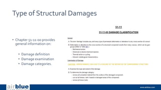
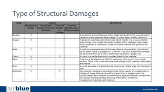
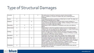
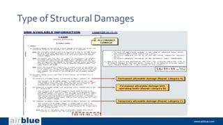
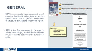
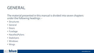
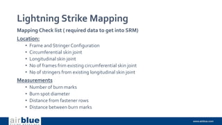
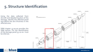
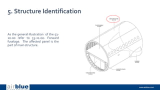
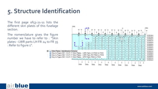
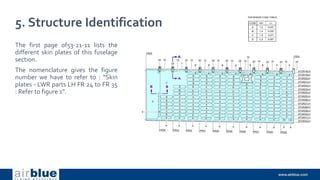
The document provides information on structural repair manuals (SRM) and damage assessment. It discusses the purpose and layout of SRM, including identification tables, allowable damage criteria, and nominal thickness determination. It also covers damage mapping and mapping examples for dents, scratches, and lightning strikes. Finally, it provides guidance on the damage assessment process, including damage identification, location mapping, measurements, structure identification, and using allowable damage information from the SRM.


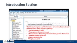


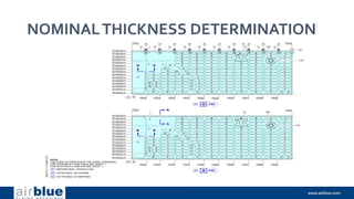

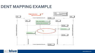

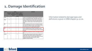
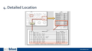
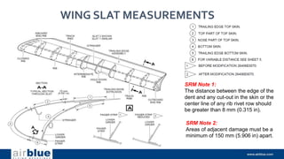
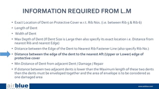
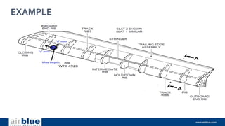
![INFORMATION REQUIRED FROM L.M
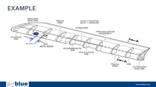
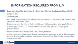
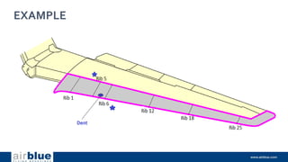
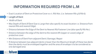
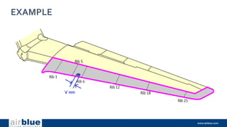
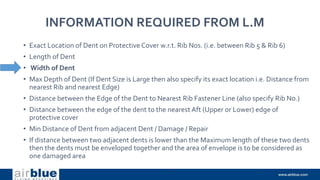
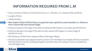
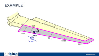
• Exact Location of Dent [i.e. On Nose part ofTop Skin between Inboard End Rib and
Rib (WFX 4920)]
• Length (SpanWise)
• Width
• Max depth with distance from nearest Rib (i.e. Inboard End Rib) and nearest Rivet Line
parallel to Slat Span (i.e. Stringer)
• Distance between Dent Edge to Closest Rib (i.e. Inboard End Rib)
• Distance between Dent Edge and Center of Stringer Rivet Line
• Min distance of Dent from adjacent Damage / Repair](https://image.slidesharecdn.com/structuretraining-220511084443-a04d403a/85/A320-Structure-Training-pptx-130-320.jpg)
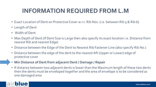
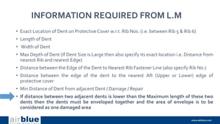
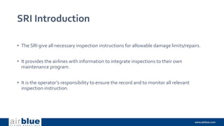
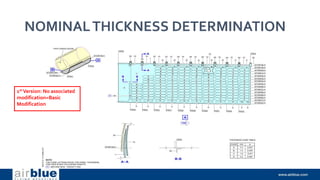
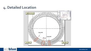
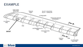
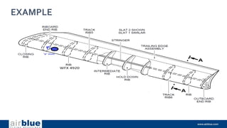
![INFORMATION REQUIRED FROM L.M
• Exact Location of Dent [i.e. On Nose part ofTop Skin between Inboard End Rib and Rib
(WFX 4920)]
• Length (Span Wise)
• Width
• Max depth with distance from nearest Rib (i.e. Inboard End Rib) and nearest Rivet Line
parallel to Slat Span (i.e. Stringer)
• Distance between Dent Edge to Closest Rib (i.e. Inboard End Rib)
• Distance between Dent Edge and Center of Stringer Rivet Line
• Min distance of Dent from adjacent Damage / Repair](https://image.slidesharecdn.com/structuretraining-220511084443-a04d403a/85/A320-Structure-Training-pptx-132-320.jpg)

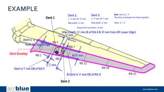
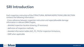
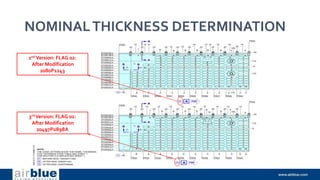
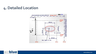
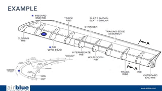
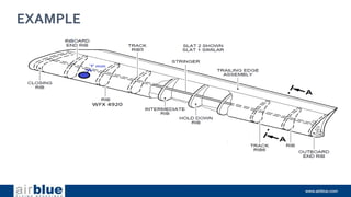
![INFORMATION REQUIRED FROM L.M
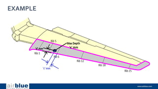
• Exact Location of Dent [i.e. On Nose part ofTop Skin between Inboard End Rib and Rib
(WFX 4920)]
• Length (SpanWise)
• Width
• Max depth with distance from nearest Rib (i.e. Inboard End Rib) and nearest Rivet Line
parallel to Slat Span (i.e. Stringer)
• Distance between Dent Edge to Closest Rib (i.e. Inboard End Rib)
• Distance between Dent Edge and Center of Stringer Rivet Line
• Min distance of Dent from adjacent Damage / Repair](https://image.slidesharecdn.com/structuretraining-220511084443-a04d403a/85/A320-Structure-Training-pptx-134-320.jpg)
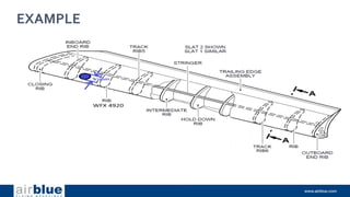
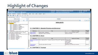
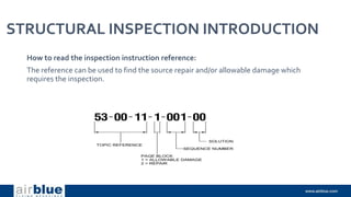
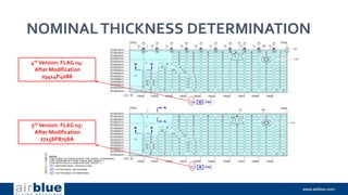
![INFORMATION REQUIRED FROM L.M
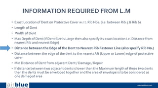
• Exact Location of Dent [i.e. On Nose part ofTop Skin between Inboard End Rib and Rib
(WFX 4920)]
• Length (SpanWise)
• Width
• Max depth with distance from nearest Rib (i.e. Inboard End Rib) and nearest Rivet
Line parallel to Slat Span (i.e. Stringer)
• Distance between Dent Edge to Closest Rib (i.e. Inboard End Rib)
• Distance between Dent Edge and Center of Stringer Rivet Line
• Min distance of Dent from adjacent Damage / Repair](https://image.slidesharecdn.com/structuretraining-220511084443-a04d403a/85/A320-Structure-Training-pptx-136-320.jpg)
![INFORMATION REQUIRED FROM L.M
• Exact Location of Dent [i.e. On Nose part ofTop Skin between Inboard End Rib and Rib
(WFX 4920)]
• Length (SpanWise)
• Width
• Max depth with distance from nearest Rib (i.e. Inboard End Rib) and nearest Rivet Line
parallel to Slat Span (i.e. Stringer)
• Distance between Dent Edge to Closest Rib (i.e. Inboard End Rib)
• Distance between Dent Edge and Center of Stringer Rivet Line
• Min distance of Dent from adjacent Damage / Repair](https://image.slidesharecdn.com/structuretraining-220511084443-a04d403a/85/A320-Structure-Training-pptx-138-320.jpg)
![INFORMATION REQUIRED FROM L.M
• Exact Location of Dent [i.e. On Nose part ofTop Skin between Inboard End Rib and Rib
(WFX 4920)]
• Length (SpanWise)
• Width
• Max depth with distance from nearest Rib (i.e. Inboard End Rib) and nearest Rivet Line
parallel to Slat Span (i.e. Stringer)
• Distance between Dent Edge to Closest Rib (i.e. Inboard End Rib)
• Distance between Dent Edge and Center of Stringer Rivet Line
• Min distance of Dent from adjacent Damage / Repair](https://image.slidesharecdn.com/structuretraining-220511084443-a04d403a/85/A320-Structure-Training-pptx-140-320.jpg)
![INFORMATION REQUIRED FROM L.M
• Exact Location of Dent [i.e. On Nose part ofTop Skin between Inboard End Rib and Rib
(WFX 4920)]
• Length (SpanWise)
• Width
• Max depth with distance from nearest Rib (i.e. Inboard End Rib) and nearest Rivet Line
parallel to Slat Span (i.e. Stringer)
• Distance between Dent Edge to Closest Rib (i.e. Inboard End Rib)
• Distance between Dent Edge and Center of Stringer Rivet Line
• Min distance of Dent from adjacent Damage / Repair](https://image.slidesharecdn.com/structuretraining-220511084443-a04d403a/85/A320-Structure-Training-pptx-142-320.jpg)