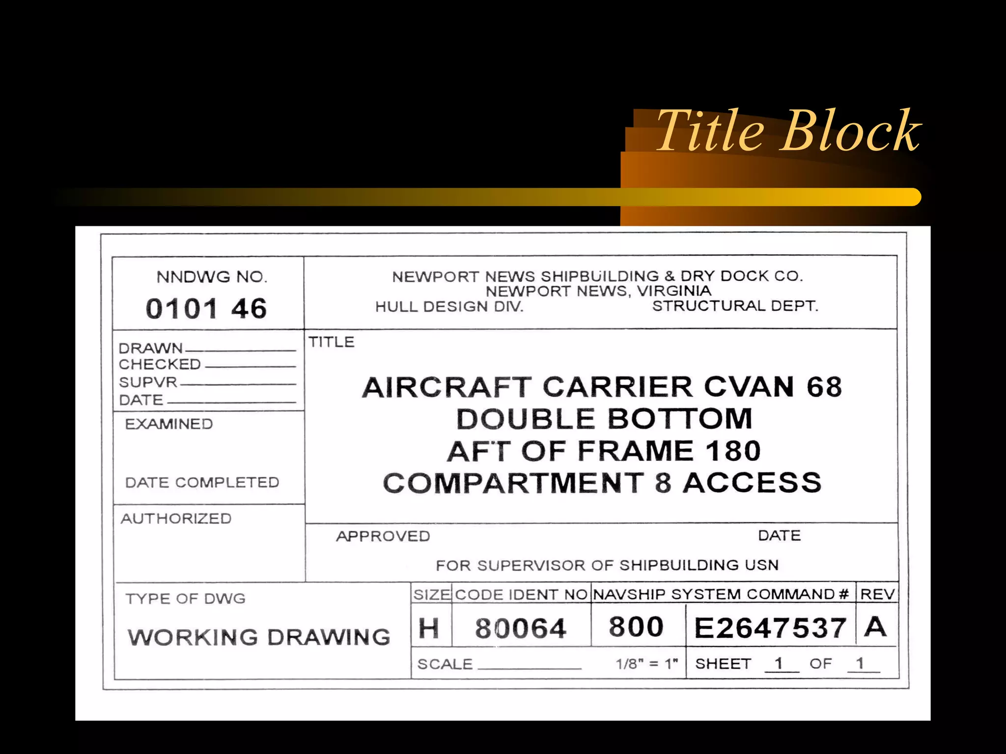
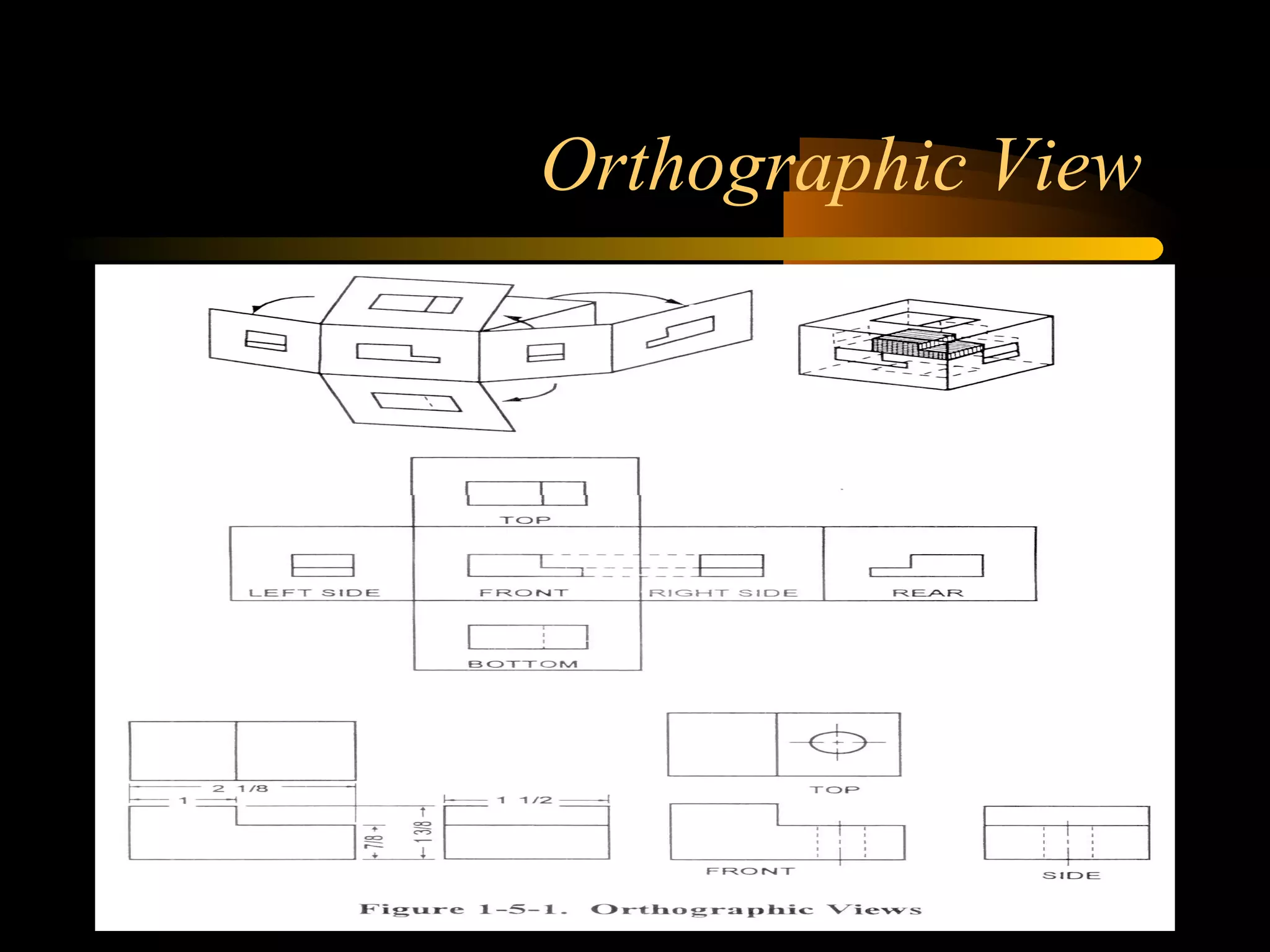
Blueprint Reading
Lesson Objectives
• Locate the title, and revision blocks on a blueprint and
state the information given in them.
• State the information given in the bill of material.
• Explain the purpose of the notes, specifications and legend
found on a blueprint.
• Identify common symbols and abbreviations found on
blueprints.
• Locate a particular point on a print using zone numbers.
• State the purpose of lines, dimensions and scale on
blueprints.
• Identify different views used in blueprints.
What is a blueprint?
• Blueprints are reproduced copies of
drawings used to represent clearly
understood pictures of objects,structures,
and systems. Basic information relevant to
the item shown on the print is found in the
title, revision and application blocks.
Location and Parts of the title
block
• The title block is usually located in the
lower right hand corner and contains:
– The drawing number.
– Name or part of the assembly.
– Basic required information.
– Name of preparing organization.
– Scale
Location/Parts of a title block
(Cont)
– Drafting record
– Authentication
– Preparation date of print.
– Reference numbers to identify the numbers of
related blueprints, modified or improved parts,
or to indicate right- or left-handed parts of an
assembly.
– Number of sheets enclosed.
Title Block
Revision Block
• The revision block is usually located in the
upper right hand corner.
• It includes a record of changes to the
original drawing. A revised print is
indicated by adding a letter to the original
number.
Revision Block
Application Block
• Located near the title block.
• Identifies directly or by reference the larger
units of the detailed part on the drawing
forms a component.
Application Block
Zone numbers
• Zone numbers on a blueprint are like grid
references on a map. To locate a particular
point on a print:
– Locate each zone number on the borders.
– Trace an imaginary line from each number
toward the opposite side.
– The area where the two lines meet gives you
the location of the point.
Bill of Material
• A list of parts or materials required by or
used on the blue print. Not only does the
bill of material list the material used, but it
also gives a description of the item.
( Weight, thickness, quantity, milspecs and
other applicable information.)
Bill of Material
Lines and Symbols
• To properly read blueprints, you must be
familiar with the lines and symbols used on
a blueprint. Various types of lines are used
to show different objects and their
positions.
Symbols and Abbreviations
• Symbols and abbreviations have been
developed to simplify blueprint reading.
• Refer to the appropriate technical
documentation as aids in identifying
abbreviations and symbols on blueprints.
• Symbols found on piping prints include:
Symbols (Cont)
– Pipe fittings-type of connections
– Elbows
– Tees
– Other pipe fittings
– Valves-types of connections
– Valve types
– Strainers
– Traps
Symbols (Cont. 2)
– Power and heating plant equiptment
– Gages, thermometers, and miscellaneous
– Refrigeration equiptment
– Pipeline Symbols
Piping Symbols
Piping Symbols 2
Abbreviations
• Some abbreviations commonly found on
piping blueprints include:
• Welding process abbreviations.
• Cutting process abbreviations.
Welding Process Abbreviations
• AAW AIR-ACETYLENE WELDING
• SAW SUBMERGED ARC WELDING
• CAW CARBON-ARC WELDING
• RSW RESISTANCE-SPOT WELDING
• RSEW RESISTANCE-SEAM WELDING
• SMAW SHIELDED METAL-ARC
WELDING
WELDING PROCESS (CONT)
• AU AUTOMATIC
• ME MACHINE
• MA MANUAL
• SA SEMI-AUTOMATIC
Cutting Process
• AAC AIR-CARBON-ARC CUTTING
• AC ARC CUTTING
• AOC OXYGEN-ARC CUTTING
• CAC CARBON -ARC CUTTING
• PAC PLASMA-ARC CUTTING
Notes or Specifications
• Notes or specifications on a blueprint provide
additional information about a drawing or
assembly.
• Notes clarify specific objects.
• Leader lines point out the exact part being noted.
• Specifications provide a description of particulars
or objects shown on a print and describe
performance requirements and items to be
obtained or maintained.
Lines
• Lines are used to indicate the shape of an
object, the limit of dimensions, and to form
blueprint symbols. Line characteristics such
as width, breaks, inline, and zigzags have
special meanings.
Lines used in Blueprints
Lines (Continued)
Dimensions
• Dimensions indicate size and location. They
are indicated by whole numbers, fractions,
decimals, or angles. Dimensions are also
used to outline shapes of objects on
drawings and prints. There are six major
kinds of dimensions:
Six Major Dimensions
• (1) Conventional dimensions give the
overall dimensions, length, width, and
height of an object.
• (2) Baseline dimensions give all the
dimensions of an object and are indicated in
relation to a designation baseline or
centerline. Baseline dimensioning is used to
mark precision parts on a drawing or print.
Six Major Dimensions (cont)
• (3) Chamfer and bevel dimensions are used
to indicate the linear and angular
dimensions of the edges of an object.
• (4) Radius and arc dimensions are used to
indicate circular or rounded portions of
objects
Six Major Dimensions (cont)
• (5) Drilled hole dimensions are shown on a
print by using a leader and a note. The
leader indicates the location of the hole; the
note lists drill size, the number of holes to
be drilled, and usually the depth of the hole
to be drilled. If the depth is not given, the
hole is to be drilled completely through the
object.
• (6) Tolerance dimensions represent the
amount by which a dimension can vary and
remain within the limits of the
specifications. Tolerances are indicated by a
plus/minus symbol _ . For example _ 1/2
inch means that the specifications allow for
a variation of 1/2 inch more or less than the
basic dimension.
Six Major Dimensions (cont)
Size and Location Dimensions
Conventional and Baseline
Dimensions
Chamfer and Bevel Dimensions
Radius and Arc Dimensions
Views
• Orthographic Views
• Section Views
• Developed Views
• Detail Drawing and Assembly Print
Orthographic Projection
• An orthographic projection shows the form
of an object by presenting various views
that have either horizontal or vertical
alignment. These views are arranged in a
particular order to present an accurate
picture of the object.
Orthographic View
Section Views
• Section views give a clearer picture of the
interior of an object or of a hidden feature
that is not visible in conventional outside
views. Section views are made by cutting
away part of the object along a given
cutting plane. Full section (cross section)
and half section views are the most
commonly used in drawings.
Section Views (cont)
• A full section ( cross section) shows an
object as if it were cut completely through
along a certain plane.
• A half section is used when the object to be
shown is symmetrical in both inside and
outside details. Only half the object is
sectioned; the other half is shown as a
standard view.
Section Views
Developments
• Developments are special views used to
show the fabrication of parts from sheet
metal. Development (pattern making or
stretchout) is the method used to make a
pattern.
Developed View
Detail Drawing and Assembly Print
Summary
• Location of title, revision, and bill of material blocks and
information contained therein.
• How to locate a particular point on a blueprint using zone
numbers.
• Identifying common symbols and abbreviations found on
blueprints.
• Explanation of the purpose of notes, specifications, and
legend found on blueprints.
• Explanation of the purpose of lines, dimensions and scale
on blueprints.
• Identification of different views used in blueprints.

Blueprint reading

  • 1.
  • 2.
    Lesson Objectives • Locatethe title, and revision blocks on a blueprint and state the information given in them. • State the information given in the bill of material. • Explain the purpose of the notes, specifications and legend found on a blueprint. • Identify common symbols and abbreviations found on blueprints. • Locate a particular point on a print using zone numbers. • State the purpose of lines, dimensions and scale on blueprints. • Identify different views used in blueprints.
  • 3.
    What is ablueprint? • Blueprints are reproduced copies of drawings used to represent clearly understood pictures of objects,structures, and systems. Basic information relevant to the item shown on the print is found in the title, revision and application blocks.
  • 4.
    Location and Partsof the title block • The title block is usually located in the lower right hand corner and contains: – The drawing number. – Name or part of the assembly. – Basic required information. – Name of preparing organization. – Scale
  • 5.
    Location/Parts of atitle block (Cont) – Drafting record – Authentication – Preparation date of print. – Reference numbers to identify the numbers of related blueprints, modified or improved parts, or to indicate right- or left-handed parts of an assembly. – Number of sheets enclosed.
  • 6.
  • 7.
    Revision Block • Therevision block is usually located in the upper right hand corner. • It includes a record of changes to the original drawing. A revised print is indicated by adding a letter to the original number.
  • 8.
  • 9.
    Application Block • Locatednear the title block. • Identifies directly or by reference the larger units of the detailed part on the drawing forms a component.
  • 10.
  • 11.
    Zone numbers • Zonenumbers on a blueprint are like grid references on a map. To locate a particular point on a print: – Locate each zone number on the borders. – Trace an imaginary line from each number toward the opposite side. – The area where the two lines meet gives you the location of the point.
  • 12.
    Bill of Material •A list of parts or materials required by or used on the blue print. Not only does the bill of material list the material used, but it also gives a description of the item. ( Weight, thickness, quantity, milspecs and other applicable information.)
  • 13.
  • 14.
    Lines and Symbols •To properly read blueprints, you must be familiar with the lines and symbols used on a blueprint. Various types of lines are used to show different objects and their positions.
  • 15.
    Symbols and Abbreviations •Symbols and abbreviations have been developed to simplify blueprint reading. • Refer to the appropriate technical documentation as aids in identifying abbreviations and symbols on blueprints. • Symbols found on piping prints include:
  • 16.
    Symbols (Cont) – Pipefittings-type of connections – Elbows – Tees – Other pipe fittings – Valves-types of connections – Valve types – Strainers – Traps
  • 17.
    Symbols (Cont. 2) –Power and heating plant equiptment – Gages, thermometers, and miscellaneous – Refrigeration equiptment – Pipeline Symbols
  • 18.
  • 19.
  • 20.
    Abbreviations • Some abbreviationscommonly found on piping blueprints include: • Welding process abbreviations. • Cutting process abbreviations.
  • 21.
    Welding Process Abbreviations •AAW AIR-ACETYLENE WELDING • SAW SUBMERGED ARC WELDING • CAW CARBON-ARC WELDING • RSW RESISTANCE-SPOT WELDING • RSEW RESISTANCE-SEAM WELDING • SMAW SHIELDED METAL-ARC WELDING
  • 22.
    WELDING PROCESS (CONT) •AU AUTOMATIC • ME MACHINE • MA MANUAL • SA SEMI-AUTOMATIC
  • 23.
    Cutting Process • AACAIR-CARBON-ARC CUTTING • AC ARC CUTTING • AOC OXYGEN-ARC CUTTING • CAC CARBON -ARC CUTTING • PAC PLASMA-ARC CUTTING
  • 24.
    Notes or Specifications •Notes or specifications on a blueprint provide additional information about a drawing or assembly. • Notes clarify specific objects. • Leader lines point out the exact part being noted. • Specifications provide a description of particulars or objects shown on a print and describe performance requirements and items to be obtained or maintained.
  • 25.
    Lines • Lines areused to indicate the shape of an object, the limit of dimensions, and to form blueprint symbols. Line characteristics such as width, breaks, inline, and zigzags have special meanings.
  • 26.
    Lines used inBlueprints
  • 27.
  • 28.
    Dimensions • Dimensions indicatesize and location. They are indicated by whole numbers, fractions, decimals, or angles. Dimensions are also used to outline shapes of objects on drawings and prints. There are six major kinds of dimensions:
  • 29.
    Six Major Dimensions •(1) Conventional dimensions give the overall dimensions, length, width, and height of an object. • (2) Baseline dimensions give all the dimensions of an object and are indicated in relation to a designation baseline or centerline. Baseline dimensioning is used to mark precision parts on a drawing or print.
  • 30.
    Six Major Dimensions(cont) • (3) Chamfer and bevel dimensions are used to indicate the linear and angular dimensions of the edges of an object. • (4) Radius and arc dimensions are used to indicate circular or rounded portions of objects
  • 31.
    Six Major Dimensions(cont) • (5) Drilled hole dimensions are shown on a print by using a leader and a note. The leader indicates the location of the hole; the note lists drill size, the number of holes to be drilled, and usually the depth of the hole to be drilled. If the depth is not given, the hole is to be drilled completely through the object.
  • 32.
    • (6) Tolerancedimensions represent the amount by which a dimension can vary and remain within the limits of the specifications. Tolerances are indicated by a plus/minus symbol _ . For example _ 1/2 inch means that the specifications allow for a variation of 1/2 inch more or less than the basic dimension. Six Major Dimensions (cont)
  • 33.
  • 34.
  • 35.
  • 36.
    Radius and ArcDimensions
  • 37.
    Views • Orthographic Views •Section Views • Developed Views • Detail Drawing and Assembly Print
  • 38.
    Orthographic Projection • Anorthographic projection shows the form of an object by presenting various views that have either horizontal or vertical alignment. These views are arranged in a particular order to present an accurate picture of the object.
  • 39.
  • 40.
    Section Views • Sectionviews give a clearer picture of the interior of an object or of a hidden feature that is not visible in conventional outside views. Section views are made by cutting away part of the object along a given cutting plane. Full section (cross section) and half section views are the most commonly used in drawings.
  • 41.
    Section Views (cont) •A full section ( cross section) shows an object as if it were cut completely through along a certain plane. • A half section is used when the object to be shown is symmetrical in both inside and outside details. Only half the object is sectioned; the other half is shown as a standard view.
  • 42.
  • 43.
    Developments • Developments arespecial views used to show the fabrication of parts from sheet metal. Development (pattern making or stretchout) is the method used to make a pattern.
  • 44.
  • 45.
    Detail Drawing andAssembly Print
  • 46.
    Summary • Location oftitle, revision, and bill of material blocks and information contained therein. • How to locate a particular point on a blueprint using zone numbers. • Identifying common symbols and abbreviations found on blueprints. • Explanation of the purpose of notes, specifications, and legend found on blueprints. • Explanation of the purpose of lines, dimensions and scale on blueprints. • Identification of different views used in blueprints.