Downloaded 319 times
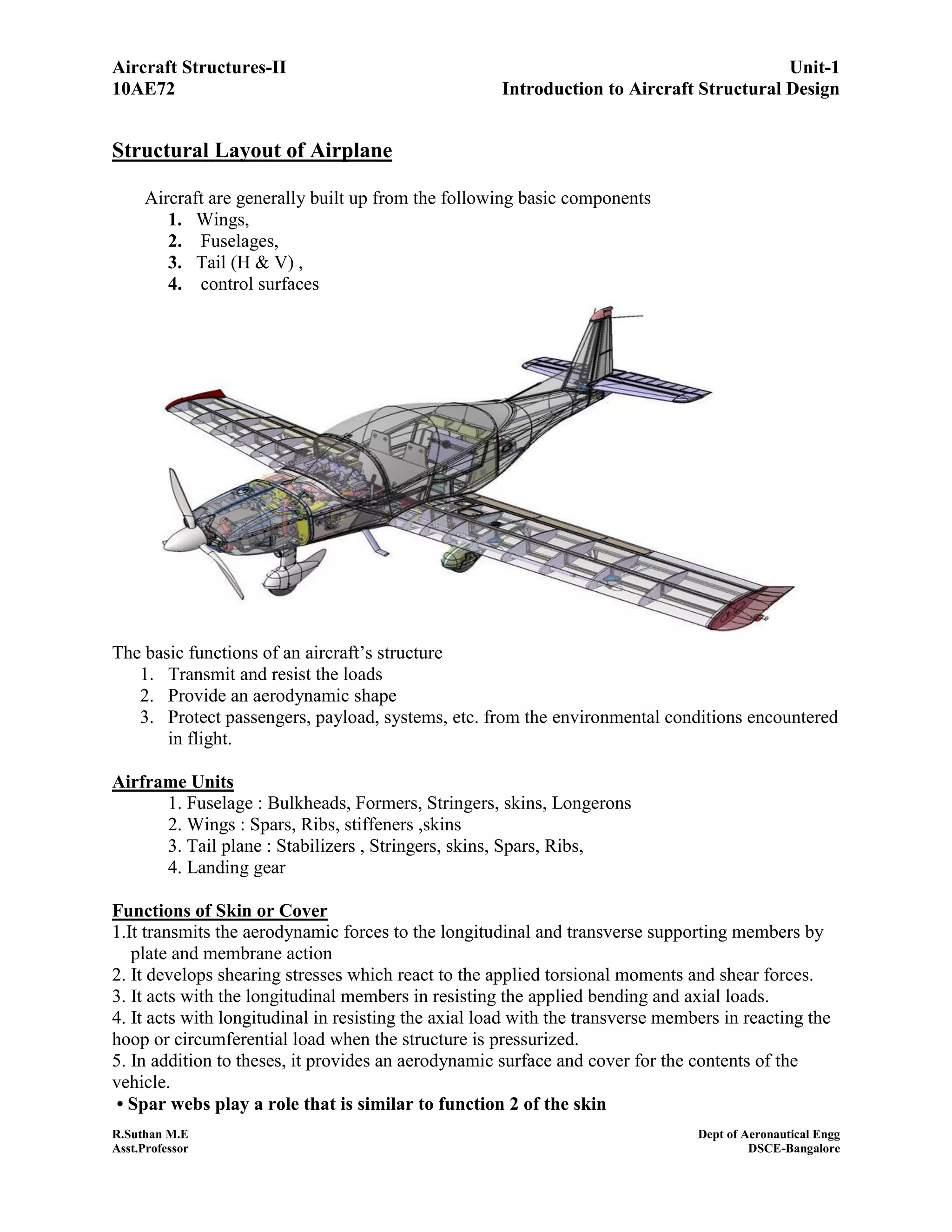
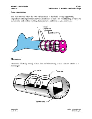
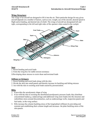

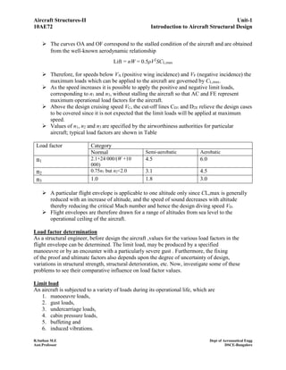
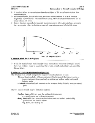
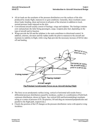
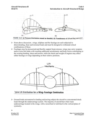
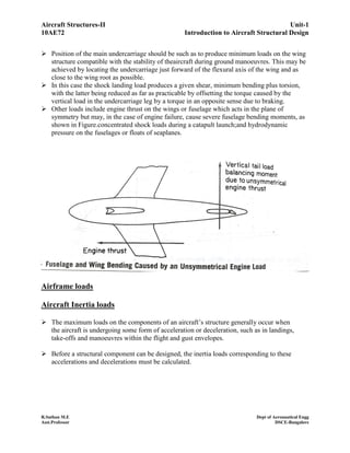

This document discusses the structural design of aircraft. It begins by describing the basic components of an aircraft structure, including wings, fuselage, tail, and control surfaces. It then discusses the functions of different structural elements like skin, spars, ribs, stringers, and frames. It provides details on fuselage types, wing structure, empennage, landing gear, and materials used in aircraft construction. It concludes with an explanation of the V-n diagram used for structural design and load factors specified by airworthiness authorities.


![[Deck] What's New in Spark-Iceberg Integration via DSV2.pptx](https://cdn.slidesharecdn.com/ss_thumbnails/deckwhatsnewinspark-icebergintegrationviadsv2-260210005337-25955b12-thumbnail.jpg?width=640&height=640&fit=bounds)


