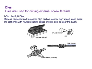
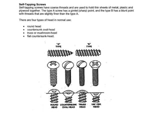
This document provides an overview of fasteners used in aircraft, including:
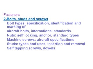
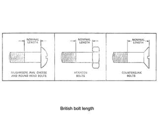
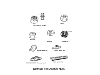
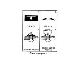
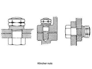
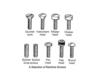
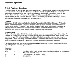
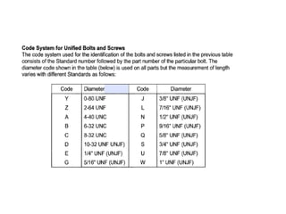
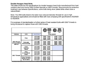
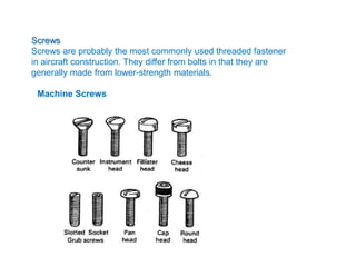
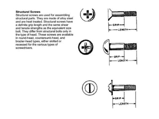
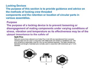
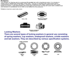
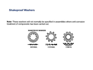
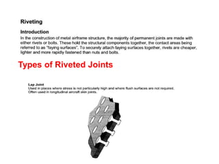
1) Screws, bolts, nuts, and locking devices used to join aircraft components. Common thread standards and specifications are discussed.
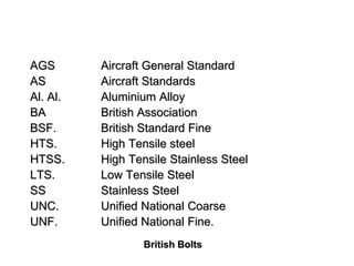
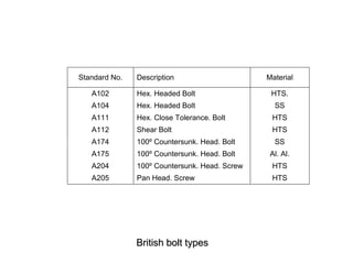
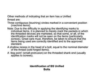
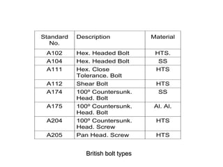
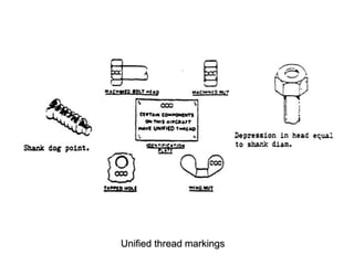
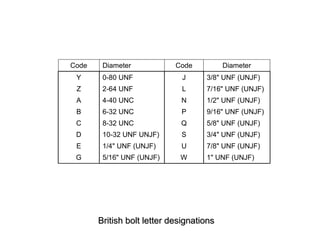
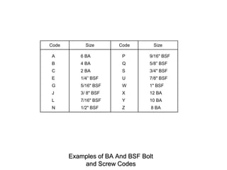
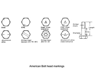
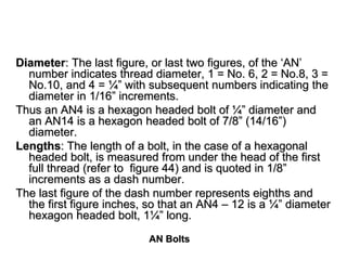
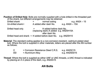
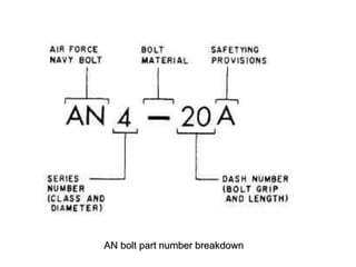
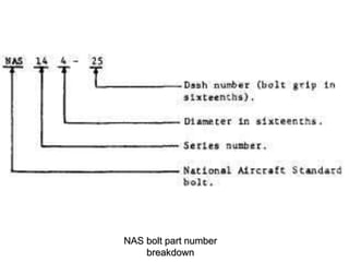
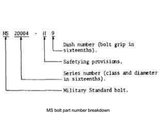
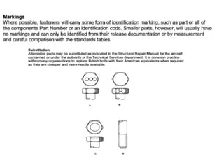
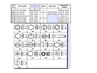
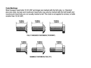
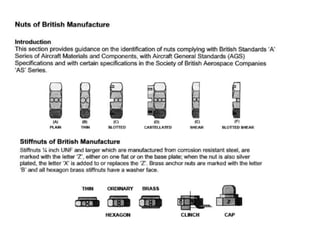
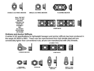
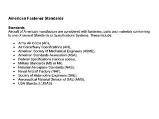
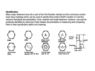
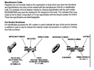
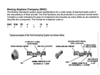
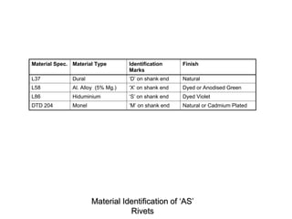
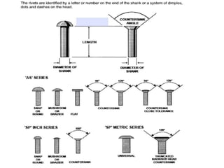
2) Fastener identification markings for British, American, and international standards are summarized to identify material, size, and other properties.
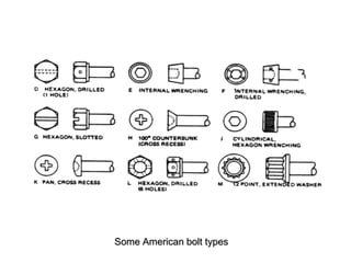
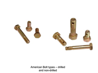
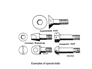
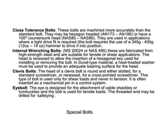
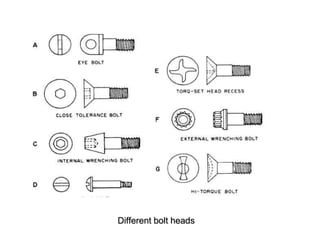
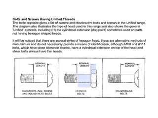
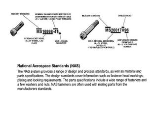
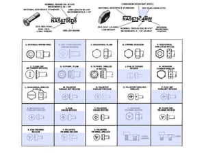
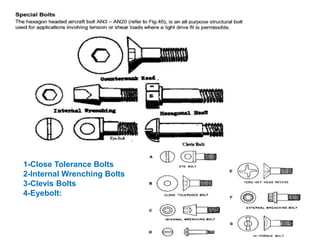
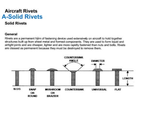
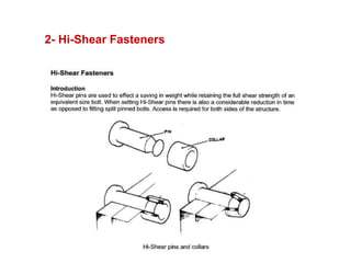
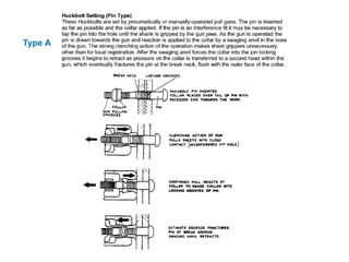
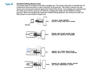
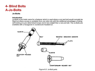
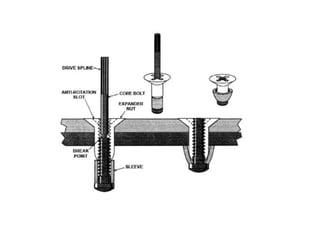
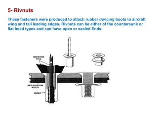
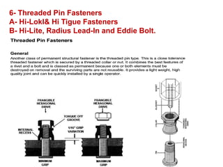
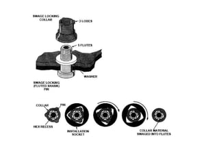
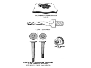
3) Specialized fasteners like close tolerance bolts and internal wrenching bolts used in aircraft are described.


![ME 312 Mechanical Machine Design [Screws, Bolts, Nuts]](https://cdn.slidesharecdn.com/ss_thumbnails/me312-dsulec10-screws-170213050612-thumbnail.jpg?width=640&height=640&fit=bounds)


