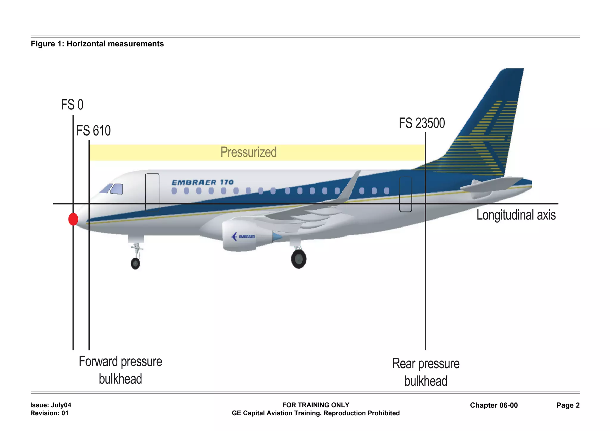
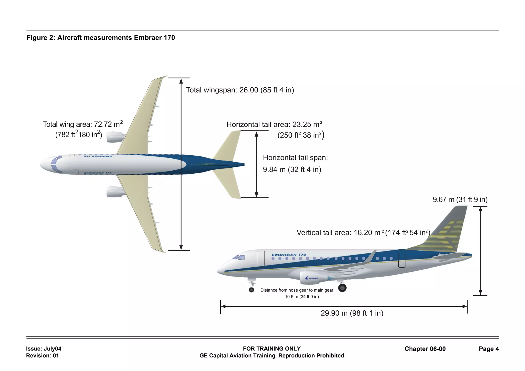
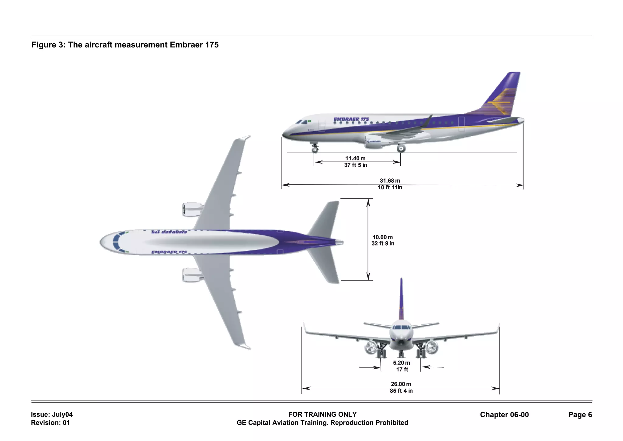
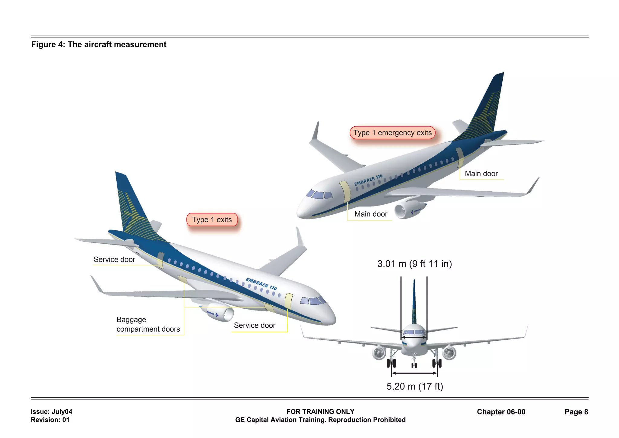
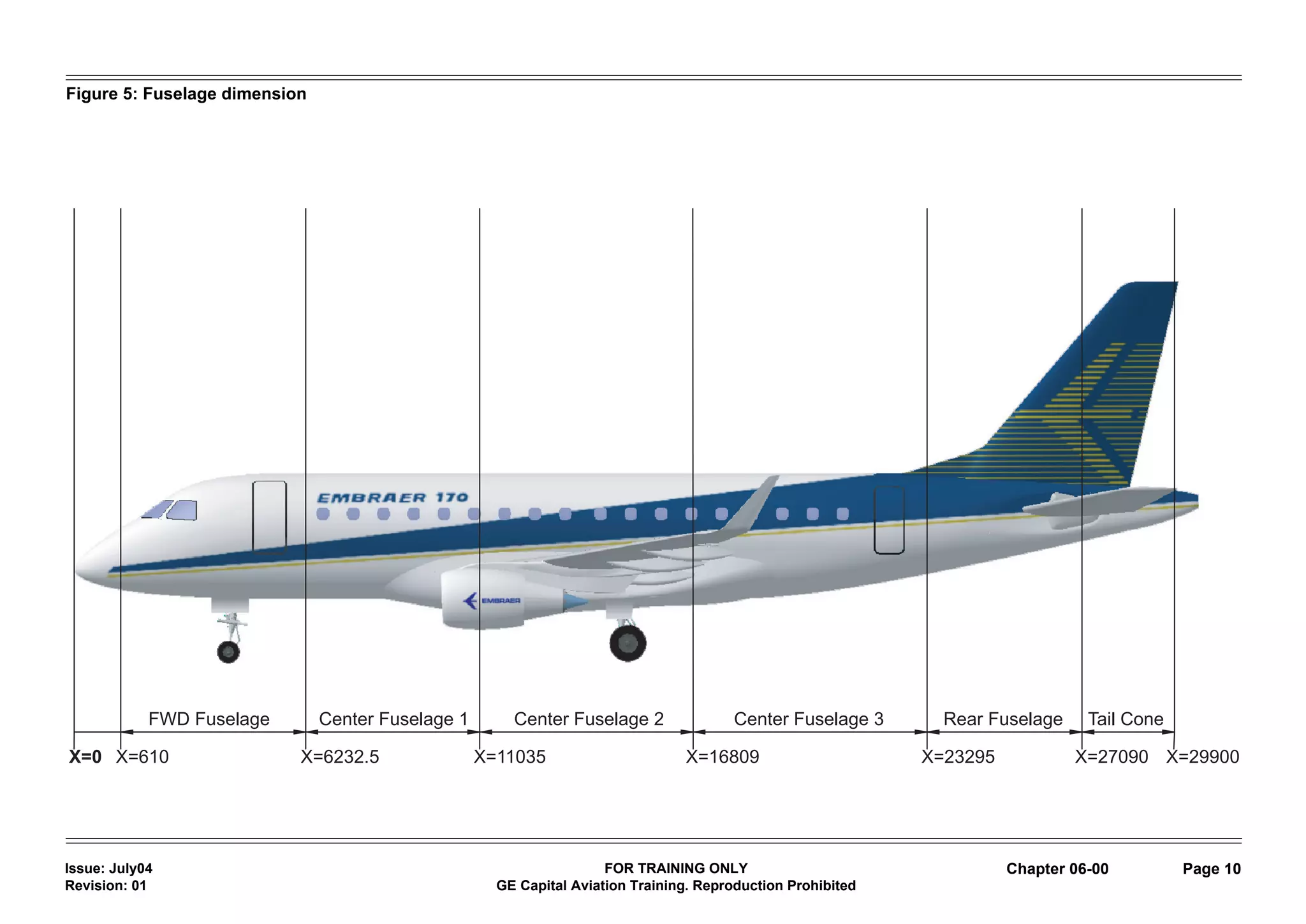
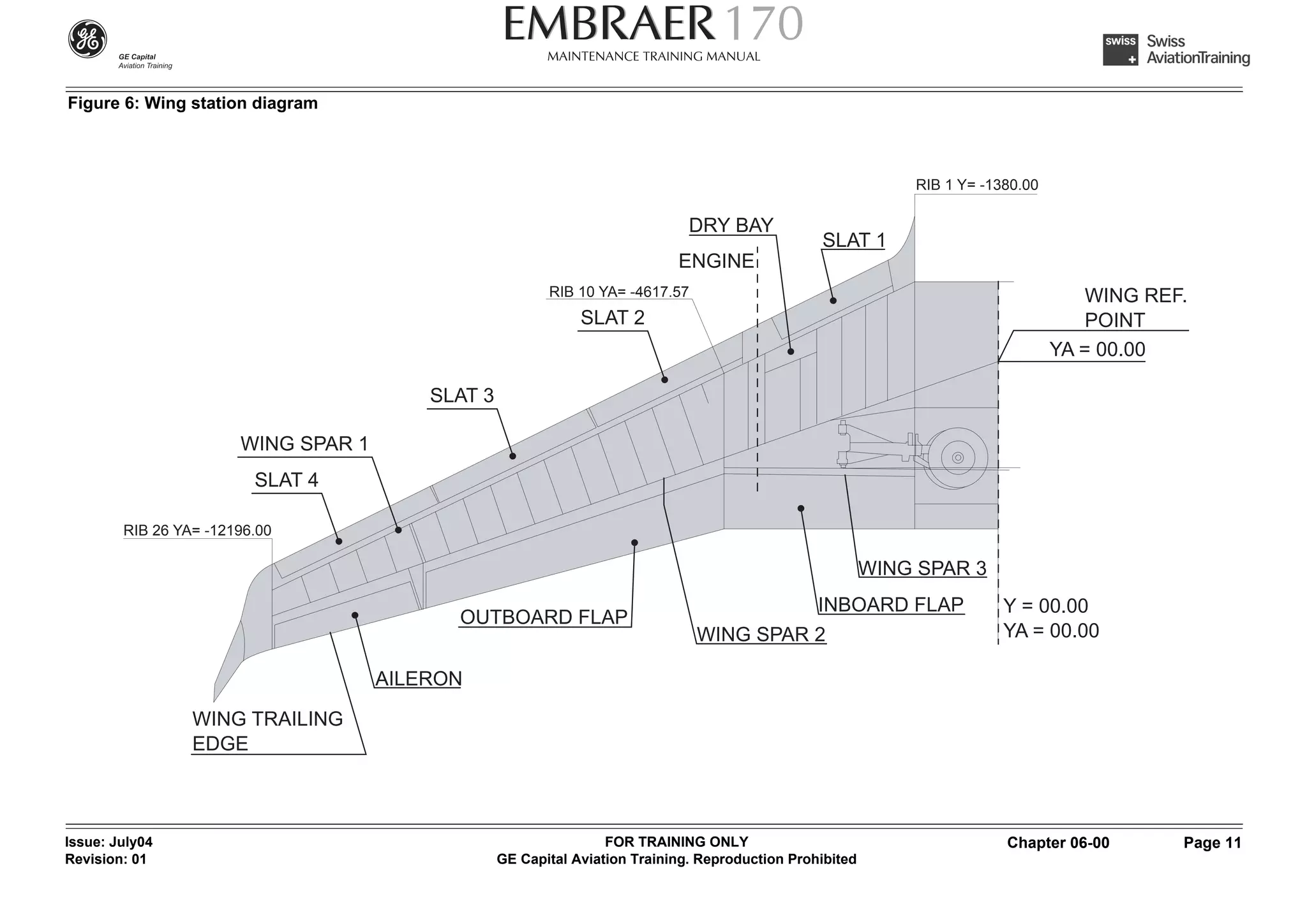
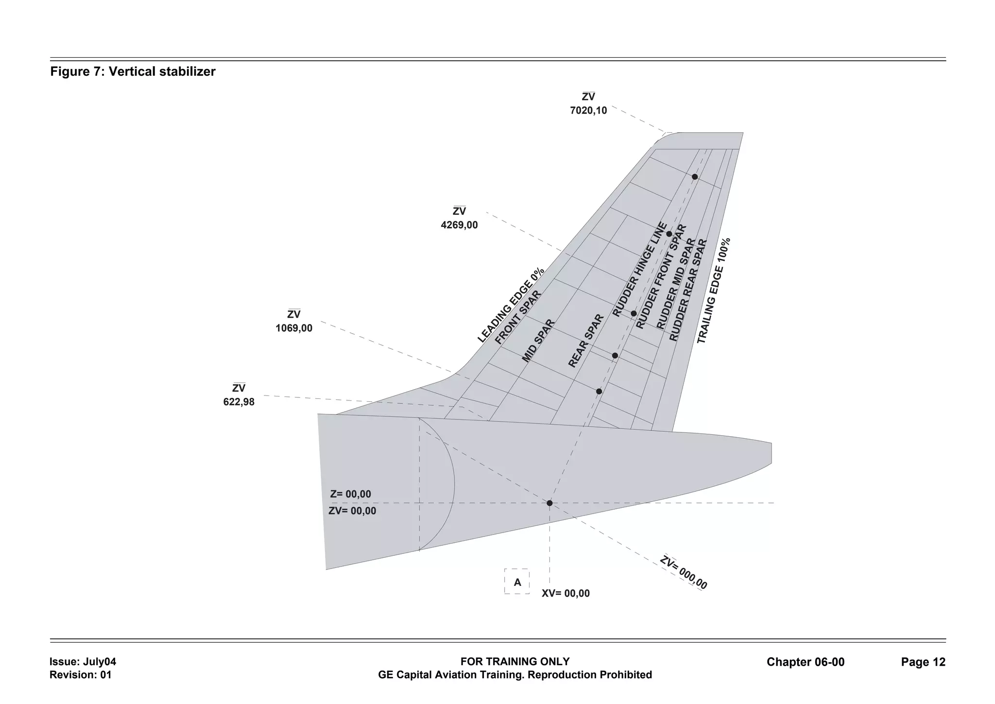
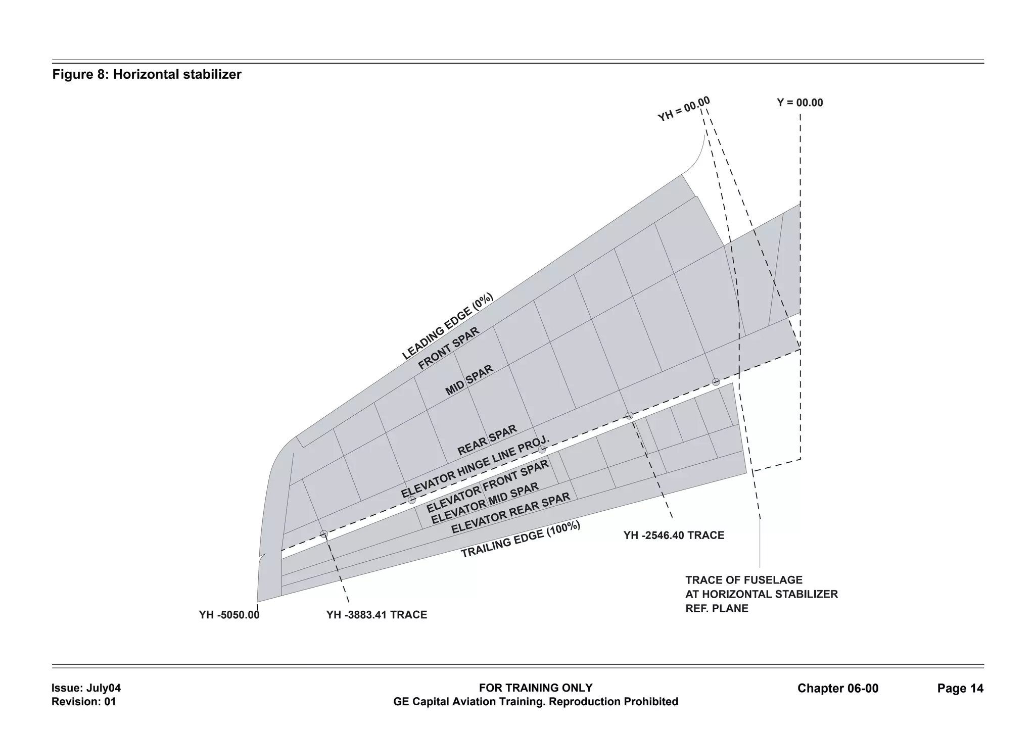
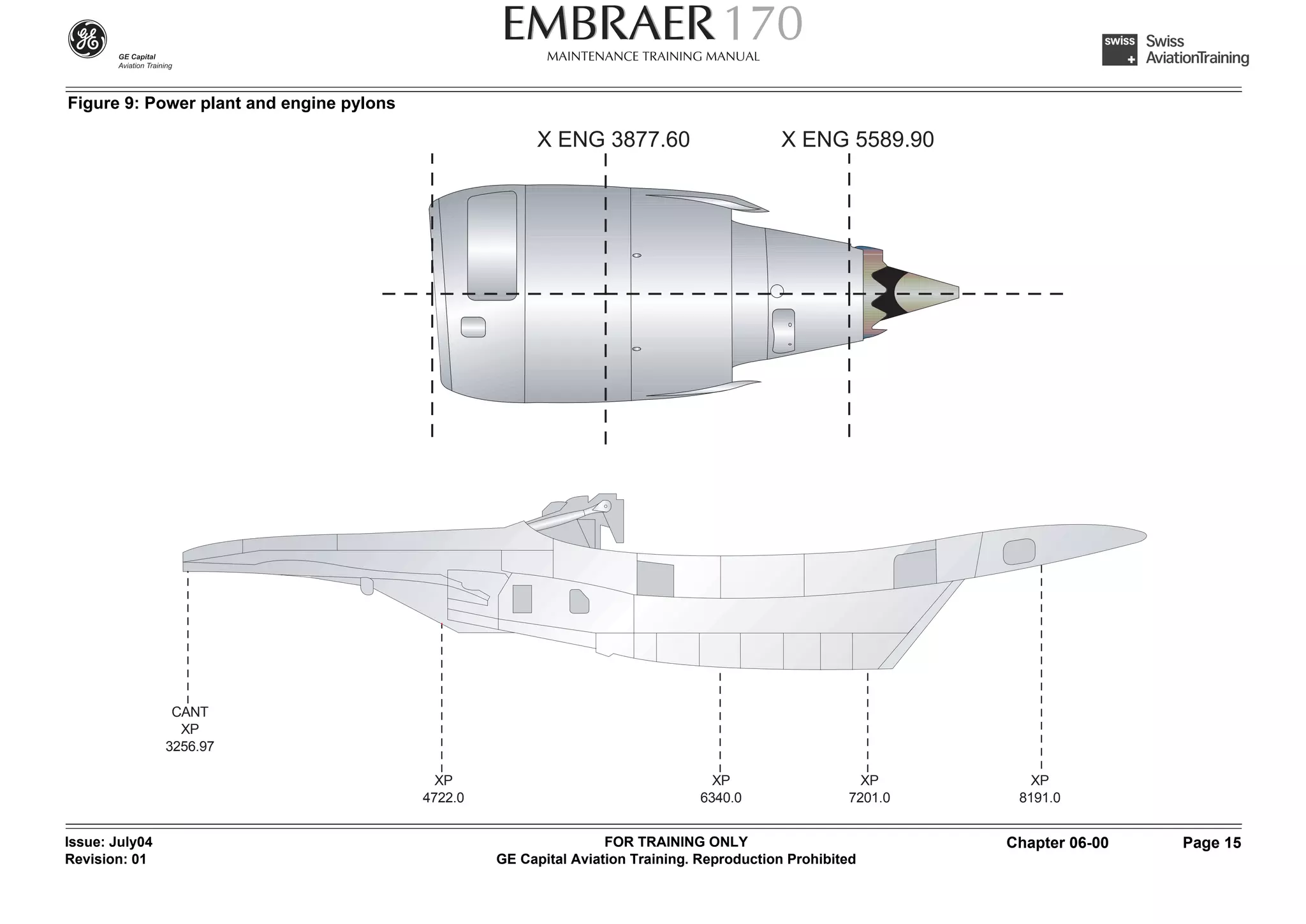
The document discusses aircraft dimensions and measurements for the Embraer 170 and 175 aircraft. It provides details on total length, height, wing span, wing and tail areas, fuselage diameter, and distances between components. Diagrams illustrate the measurements. The aircraft use a coordinate system to define stations along the longitudinal, lateral, and vertical axes from a point of origin at the front of the aircraft.
This presentation is an examination of structural repair of aircraft. It details the goals, regulations and classification of repairs for different types of aircraft damage.
The paper that this presentation is based on was presented by Dr. Kishore Brahma of the AXISCADES Engineering Core Group at the International Conference & Exhibition on Fatigue, Durability & Fracture Mechanics (FatigueDurabilityIndia2015) in Bangalore from 28-30th May 2015.
Design and Linear Static Analysis of Transport Aircraft Vertical Tail for Dif...IJSRD
The design of vertical tail structure varies according to nature of aircraft and its function. The experimental test of vertical tail structure is difficult and more expensive process. In this present work detailed design of transport aircraft vertical tail with rudder structure modelling done by using CATIA V5 R19 software. The static stress analysis is carried out to find the stresses at of the vertical tail with rudder structure for different deflection of rudder. The stresses are estimated to find the safety factor of the structure using finite element approach with the help of MSC/PATRAN and MSC/NASTRAN software. The material used in the vertical tail structure is aluminium 7075-T6, which has high fatigue strength. From the analysis it is found that maximum principal stress of vertical tail structure is less than yield strength of aluminium 7075-T6 alloy. The maximum principal stress value form analysis is used to find fatigue damage calculations for vertical tail structure. The obtained analytical result shows that safe no of fatigue life hours of vertical tail structure. The result is verified with reserve factor approach.
A look into historical evolution of materials used for aircraft manufacturing by 5 aircraft manufacturers with consideration to material selection aspects of it.
Airbus - Topology Optimization Methods for Optimal Aircraft ComponentsAltair ProductDesign
Application of Topology, Sizing and Shape Optimization Methods to Optimal Design of Aircraft Components - a Technical Engineering & Analysis Paper from Altair ProductDesign
ME438 Aerodynamics is offered by Dr. Bilal Siddiqui to senior mechanical engineeing undergraduates at DHA Suffa University. This lecture set is an introduction to aircraft design using Raymer's methods.
Operation “Blue Star” is the only event in the history of Independent India where the state went into war with its own people. Even after about 40 years it is not clear if it was culmination of states anger over people of the region, a political game of power or start of dictatorial chapter in the democratic setup.
The people of Punjab felt alienated from main stream due to denial of their just demands during a long democratic struggle since independence. As it happen all over the word, it led to militant struggle with great loss of lives of military, police and civilian personnel. Killing of Indira Gandhi and massacre of innocent Sikhs in Delhi and other India cities was also associated with this movement.
Palestine last event orientationfvgnh .pptxRaedMohamed3
An EFL lesson about the current events in Palestine. It is intended to be for intermediate students who wish to increase their listening skills through a short lesson in power point.
Model Attribute Check Company Auto PropertyCeline George
In Odoo, the multi-company feature allows you to manage multiple companies within a single Odoo database instance. Each company can have its own configurations while still sharing common resources such as products, customers, and suppliers.
Biological screening of herbal drugs: Introduction and Need for
Phyto-Pharmacological Screening, New Strategies for evaluating
Natural Products, In vitro evaluation techniques for Antioxidants, Antimicrobial and Anticancer drugs. In vivo evaluation techniques
for Anti-inflammatory, Antiulcer, Anticancer, Wound healing, Antidiabetic, Hepatoprotective, Cardio protective, Diuretics and
Antifertility, Toxicity studies as per OECD guidelines
June 3, 2024 Anti-Semitism Letter Sent to MIT President Kornbluth and MIT Cor...Levi Shapiro
Letter from the Congress of the United States regarding Anti-Semitism sent June 3rd to MIT President Sally Kornbluth, MIT Corp Chair, Mark Gorenberg
Dear Dr. Kornbluth and Mr. Gorenberg,
The US House of Representatives is deeply concerned by ongoing and pervasive acts of antisemitic
harassment and intimidation at the Massachusetts Institute of Technology (MIT). Failing to act decisively to ensure a safe learning environment for all students would be a grave dereliction of your responsibilities as President of MIT and Chair of the MIT Corporation.
This Congress will not stand idly by and allow an environment hostile to Jewish students to persist. The House believes that your institution is in violation of Title VI of the Civil Rights Act, and the inability or
unwillingness to rectify this violation through action requires accountability.
Postsecondary education is a unique opportunity for students to learn and have their ideas and beliefs challenged. However, universities receiving hundreds of millions of federal funds annually have denied
students that opportunity and have been hijacked to become venues for the promotion of terrorism, antisemitic harassment and intimidation, unlawful encampments, and in some cases, assaults and riots.
The House of Representatives will not countenance the use of federal funds to indoctrinate students into hateful, antisemitic, anti-American supporters of terrorism. Investigations into campus antisemitism by the Committee on Education and the Workforce and the Committee on Ways and Means have been expanded into a Congress-wide probe across all relevant jurisdictions to address this national crisis. The undersigned Committees will conduct oversight into the use of federal funds at MIT and its learning environment under authorities granted to each Committee.
• The Committee on Education and the Workforce has been investigating your institution since December 7, 2023. The Committee has broad jurisdiction over postsecondary education, including its compliance with Title VI of the Civil Rights Act, campus safety concerns over disruptions to the learning environment, and the awarding of federal student aid under the Higher Education Act.
• The Committee on Oversight and Accountability is investigating the sources of funding and other support flowing to groups espousing pro-Hamas propaganda and engaged in antisemitic harassment and intimidation of students. The Committee on Oversight and Accountability is the principal oversight committee of the US House of Representatives and has broad authority to investigate “any matter” at “any time” under House Rule X.
• The Committee on Ways and Means has been investigating several universities since November 15, 2023, when the Committee held a hearing entitled From Ivory Towers to Dark Corners: Investigating the Nexus Between Antisemitism, Tax-Exempt Universities, and Terror Financing. The Committee followed the hearing with letters to those institutions on January 10, 202
Acetabularia Information For Class 9 .docxvaibhavrinwa19
Acetabularia acetabulum is a single-celled green alga that in its vegetative state is morphologically differentiated into a basal rhizoid and an axially elongated stalk, which bears whorls of branching hairs. The single diploid nucleus resides in the rhizoid.
Read| The latest issue of The Challenger is here! We are thrilled to announce that our school paper has qualified for the NATIONAL SCHOOLS PRESS CONFERENCE (NSPC) 2024. Thank you for your unwavering support and trust. Dive into the stories that made us stand out!
3. Intentionally left blank
Issue: July04 FOR TRAINING ONLY
Revision: 00 GE Capital Aviation Training. Reproduction Prohibited TOC 06 Page 2
4. 06-00 Aircraft areas and dimensions
Introduction
This chapter describes the aircraft’s general external dimensions, aircraft
zoning and station identification. The fuselage stations show the length
measurements along the longitudinal axis.
All horizontal measurements are taken from the datum line FS 0 which is lo-
cated at the nose tip. The forward pressure bulkhead is located at station
610 and the fuselage is pressurized between the forward pressure bulkhead
and the rear pressure bulkhead, which is located at station 23500.
Issue: July04 FOR TRAINING ONLY Chapter 06-00 Page 1
Revision: 01 GE Capital Aviation Training. Reproduction Prohibited
5. Figure 1: Horizontal measurements
FS 0
FS 23500
FS 610
Longitudinal axis
Forward pressure Rear pressure
bulkhead bulkhead
Issue: July04 FOR TRAINING ONLY Chapter 06-00 Page 2
Revision: 01 GE Capital Aviation Training. Reproduction Prohibited
6. The aircraft measurement Embraer 170
The aircraft has a total length from the nose to the tail of 29.90m (98 ft 1 in.),
the height from the ground to the top of the vertical tail is 9.67m (31 ft 9 in.)
and a vertical tail area of 16.20 m² (174 ft² 54 in²).
The distance from the nose gear to the main gear is 10.60 meters (34ft 9 in).
The aircraft has a total wing span of 26.00m (85 ft 4 in) with a total wing area
of 72.72 m² (782 ft² 180 in²), a horizontal tail span of 9.84 m (32 ft 4 in.), with
a horizontal tail area of 23.25 m² (250 ft² 38 in²) and a fuselage external di-
ameter of 3.01 m (9 ft 11 in.).
The distance from the left to right main gear is 5.20 meters (17ft).
Issue: July04 FOR TRAINING ONLY Chapter 06-00 Page 3
Revision: 01 GE Capital Aviation Training. Reproduction Prohibited
7. Figure 2: Aircraft measurements Embraer 170
Total wingspan: 26.00 (85 ft 4 in)
Total wing area: 72.72 m 2 Horizontal tail area: 23.25 m 2
2
(782 ft 180 in2) (250 ft 2 38 in 2)
Horizontal tail span:
9.84 m (32 ft 4 in)
9.67 m (31 ft 9 in)
Vertical tail area: 16.20 m 2 (174 ft 2 54 in2 )
Distance from nose gear to main gear:
10.6 m (34 ft 9 in)
29.90 m (98 ft 1 in)
Issue: July04 FOR TRAINING ONLY Chapter 06-00 Page 4
Revision: 01 GE Capital Aviation Training. Reproduction Prohibited
8. The aircraft measurement Embraer 175
The aircraft has a total length from the nose to the tail of 31.68m (103 ft 11
in.), the height from the ground to the top of the vertical tail is 9.73m (31ft 9
in.) and a vertical tail area of 16.20m² (174 ft² 54 in²).
The distance from the nose gear to the main gear is 11.40 meters (37ft 5 in).
The aircraft has a total wing span of 26.00 meters (85 ft 4 in) with a total wing
area of 72.72 m² (782 ft² 180 in²), a horizontal tail span of 10.00 meters (32
ft 9 in), with a horizontal tail area of 23.25m² (250 ft² 38 in²) and a fuselage
external diameter of 3.01 m (9 ft 11 in).
The distance from the left to the right main gear is 5.20 meters (17 ft).
Issue: July04 FOR TRAINING ONLY Chapter 06-00 Page 5
Revision: 01 GE Capital Aviation Training. Reproduction Prohibited
9. Figure 3: The aircraft measurement Embraer 175
11.40 m
37 ft 5 in
31.68 m
10 ft 11in
10.00 m
32 ft 9 in
5.20 m
17 ft
26.00 m
85 ft 4 in
Issue: July04 FOR TRAINING ONLY Chapter 06-00 Page 6
Revision: 01 GE Capital Aviation Training. Reproduction Prohibited
10. The aircraft measurement
Located on the left side of the fuselage are two main doors, which qualifies
as type 1 emergency exits. Located on the right side of the fuselage are two
service doors, which qualify as type 1 exits, and two baggage compartment
doors.
Issue: July04 FOR TRAINING ONLY Chapter 06-00 Page 7
Revision: 01 GE Capital Aviation Training. Reproduction Prohibited
11. Figure 4: The aircraft measurement
Type 1 emergency exits
Main door
Main door
Type 1 exits
Service door
3.01 m (9 ft 11 in)
Baggage
Service door
compartment doors
5.20 m (17 ft)
Issue: July04 FOR TRAINING ONLY Chapter 06-00 Page 8
Revision: 01 GE Capital Aviation Training. Reproduction Prohibited
12. The aircraft stations
The aircraft stations are defined by a coordinate system using three main
reference axes. The point of origin for the longitudinal axis X, laterall axis Y
and vertical axis Z is in front of the aircraft.
The ordinates are identified by the letter for the major axes, followed by the
dimension in inches from the point of origin.
There are additional points of origin selected for locating major assemblies.
These points are identified with a suffix letter indicating the assembly. These
assemblies are the wings, the vertical stabilizer, the horizontal stabilizer, the
power plant and the engine pylons.
Issue: July04 FOR TRAINING ONLY Chapter 06-00 Page 9
Revision: 01 GE Capital Aviation Training. Reproduction Prohibited
13. Figure 5: Fuselage dimension
FWD Fuselage Center Fuselage 1 Center Fuselage 2 Center Fuselage 3 Rear Fuselage Tail Cone
X=0 X=610 X=6232.5 X=11035 X=16809 X=23295 X=27090 X=29900
Issue: July04 FOR TRAINING ONLY Chapter 06-00 Page 10
Revision: 01 GE Capital Aviation Training. Reproduction Prohibited
14. Figure 6: Wing station diagram
RIB 1 Y= -1380.00
DRY BAY
SLAT 1
ENGINE
RIB 10 YA= -4617.57 WING REF.
SLAT 2 POINT
YA = 00.00
SLAT 3
WING SPAR 1
SLAT 4
RIB 26 YA= -12196.00
WING SPAR 3
INBOARD FLAP Y = 00.00
OUTBOARD FLAP
WING SPAR 2 YA = 00.00
AILERON
WING TRAILING
EDGE
Issue: July04 FOR TRAINING ONLY Chapter 06-00 Page 11
Revision: 01 GE Capital Aviation Training. Reproduction Prohibited
15. Figure 7: Vertical stabilizer
ZV
7020,10
ZV
4269,00
ZV
1069,00
ZV
622,98
Z= 00,00
ZV= 00,00
A
XV= 00,00
Issue: July04 FOR TRAINING ONLY Chapter 06-00 Page 12
Revision: 01 GE Capital Aviation Training. Reproduction Prohibited
16. Issue: July04 FOR TRAINING ONLY Chapter 06-00 Page 13
Revision: 01 GE Capital Aviation Training. Reproduction Prohibited
17. Figure 8: Horizontal stabilizer
Y = 00.00
YH -2546.40 TRACE
YH -5050.00 YH -3883.41 TRACE
Issue: July04 FOR TRAINING ONLY Chapter 06-00 Page 14
Revision: 01 GE Capital Aviation Training. Reproduction Prohibited
18. Figure 9: Power plant and engine pylons
X ENG 3877.60 X ENG 5589.90
CANT
XP
3256.97
XP XP XP XP
4722.0 6340.0 7201.0 8191.0
Issue: July04 FOR TRAINING ONLY Chapter 06-00 Page 15
Revision: 01 GE Capital Aviation Training. Reproduction Prohibited
19. The aircraft zoning system
The aircraft zoning system provides identification of areas in the aircraft ac-
cording to 8 major zones, major sub-zones and zones.
The major aircraft zones are:
• The lower fuselage, zone 100
• The upper fuselage, zone 200
• The tail cone and horizontal and vertical tail, zone 300
• The power plants and pylons, zone 400
• The left wing, zone 500
• The right wing, zone 600
• The landing gear and landing gear wheel well doors, zone 700
• The aircraft doors, zone 800
Issue: July04 FOR TRAINING ONLY Chapter 06-00 Page 16
Revision: 01 GE Capital Aviation Training. Reproduction Prohibited
20. Figure 10: The major aircraft zones
Right wing Tail cone and horizontal
zone 600 and vertical tail
Power - plants zone 300
and pylons
Upper fuselage zone 400
zone 200
Doors
zone 800
Left wing
zone 500
Lower fuselage Landing gears
zone 100 and gear wheel - well doors 700
Issue: July04 FOR TRAINING ONLY Chapter 06-00 Page 17
Revision: 01 GE Capital Aviation Training. Reproduction Prohibited
21. Sub zones
The major zones are divided into major sub-zones, which are shown by the
second digit of the major zone number.The major sub-zones are further di-
vided into zones using the third digit of the major zone number.
Issue: July04 FOR TRAINING ONLY Chapter 06-00 Page 18
Revision: 01 GE Capital Aviation Training. Reproduction Prohibited
22. Figure 11: Sub-zones
ZONE 116
ZONE 115
ZONE 114
Zone number
ZONE 113
ZONE 111
SUBZONE 170
SUBZONE 160
SUBZONE 150
SUBZONE 140
SUBZONE 130
SUBZONE 120
SUBZONE 110 Subzone number
Issue: July04 FOR TRAINING ONLY Chapter 06-00 Page 19
Revision: 01 GE Capital Aviation Training. Reproduction Prohibited
23. Access panels
To carry out maintenance on aircraft systems and their components, or to
perform inspection of the aircraft structure, adequate access panels and
doors are provided in the aircraft surface.
Each access panel has an identification number which consists of a three
digit zone number followed by two or three letters.The first letter shows the
number of the panel within the zone in a logical in a logical sequence and
the second letter indicates the location of the panel in relation to the air-
craft.An optional third letter is used to identify a floor, wall or ceiling panel.
Each panel has a fastener identification code, which identifies the type and
the quantity of the fasteners for each panel.
Issue: July04 FOR TRAINING ONLY Chapter 06-00 Page 20
Revision: 01 GE Capital Aviation Training. Reproduction Prohibited
24. Figure 12: Access panels identification letters
191 DL
191 EL
192 CL
192 BL
192 AL
195 HL
195 FL
195 JL
191 AL
195 KL
195 GL
191 BL 191 CL
195 EL
Shows the number of the Indicates the location of the
panel within the zone panel in relation to the aircraft 195 AL 195 DL
195 BL 195 CL
19 S
An optional third letter is used to identify a floor(F), wall(W) or ceiling(C) panel. 19 S
Each panel has a fastener identification code:
L = Latch
S = Screw
C = Camloc
Issue: July04 FOR TRAINING ONLY Chapter 06-00 Page 21
Revision: 01 GE Capital Aviation Training. Reproduction Prohibited