Download to read offline
![Sweety Kashyap et al Int. Journal of Engineering Research and Applications
ISSN : 2248-9622, Vol. 4, Issue 1( Version 1), January 2014, pp.177-181
RESEARCH ARTICLE
www.ijera.com
OPEN ACCESS
Implementation of High Performance Fir Filter Using Low Power
Multiplier and Adder
Sweety Kashyap1, Mukesh Maheshwari2
Research Scholar, Department of Electronics and Communication1
Assistant Professor, Department of Electronics and Communication2
Jaipur National University, Jaipur, Rajasthan, India
ABSTRACT
The ever increasing growth in laptop and portable systems in cellular networks has intensified the research
efforts in low power microelectronics. Now a day, there are many portable applications requiring low power and
high throughput than ever before. Thus, low power system design has become a significant performance goal.
So this paper is face with more constraints: high speed, high throughput, and at the same time, consumes as
minimal power as possible. The Finite Impulse Response (FIR) Filter is the important component for designing
an efficient digital signal processing system. So, in this paper author trying, a FIR filter is constructing, which is
efficient not only in terms of power and speed but also in terms of delay. When consider the elementary
structure of an FIR filter, it is found that it is a combination of multipliers and delays, which in turn are the
combination of adders. . This paper presents an efficient implementation and analysis for performance
evaluation of multiplier and adder to minimize the consumption of energy during multiplication and addition
methodology to improve the performance by compares different type of Multipliers and adder, respectively. By
using, power comparison result of adders and multiplier, choice low power adder and multiplier to
implementation of high performance FIR filter.
Keywords – DSP, FPGA, Multiplier, VHDL
I.
INTRODUCTION
In today scenario low power consumption
and smaller area are the most important parameter for
the fabrication of DSP systems and high performance
systems. To save notable power consumption of a
DSP system, it is good to reduce its dynamic power
that is the important part of total power dissipation.
Digital filter are essential elements of DSP system.
Digital filter can be realized by different digital filter
structure such as direct form-I & II, transposed
structure etc. These structures provide a space for
selection of appropriate structure for minimizing of
power consumption and improvement in speed of
digital filter which is play important role in all high
performance DSP applications.[4] FIR filter and IIR
filter are two types of Digital filter. FIR filter mostly
pefer over IIR filter due to its linear phase
characteristics, low coefficient sensitivity, guarantee
stability.
Multiplication
and
addition
occurs
frequently in „Finite Impulse Response‟ (FIR). In FIR
filter, multiplier and adder plays an important role. A
multiplier in a FIR filter is most power consumption
component. Multiply and Accumulate (MAC) is an
important unit of DSP system. It decides the power
consumption and speed of operation of DSP system.
www.ijera.com
Most of DSP consumption involve the use of
multiplier accumulate operation and therefore the
design of fast and efficient multiplier imperative. .
The dynamic switching power consumption of digital
FIR filter is reduced by using data transition power
diminution technique. This technique is used on
adder, multiplier and applied for filters to remove
power consumption caused by unwanted data
transmission.
II.
FIR FILTER THEORY
Finite Impulse Response (FIR) filter are type
of digital filter and consist of weighting sequence
(impulse response) among non-recursive digital filters
which is finite in length. FIR filters are non-recursive
digital filters has been selected for this thesis due to
their good characteristics.[4] FIR filter has no
feedback and its input-output relation is given by
Here, x [n] and y [n] are the filter input and
filter output respectively, a [k] is the filter
coefficients, N is the filter coefficient number.
177 | P a g e](https://image.slidesharecdn.com/ae4101177181-140130004132-phpapp01/85/Ae4101177181-1-320.jpg)
![Sweety Kashyap et al Int. Journal of Engineering Research and Applications
ISSN : 2248-9622, Vol. 4, Issue 1( Version 1), January 2014, pp.177-181
www.ijera.com
Ci+1 = Gi or Pi Ci
Si = Pi xor Ci
here,
Gi = Ai and Bi
Pi = Ai xor Bi
Pi and Gi are known as the carry generate and carry
propagate terms, respectively.
Fig. 1: FIR Filter
As shown in figure output y [n] of a FIR
filter is a function only of the input signal x [n]. The
response of such a filter to an impulse consists of a
finite sequence of N+1 samples, where N is the filter
order.
III.
DIGITAL ADDERS
3.1 RIPPLE CARRY ADDER
A simple Ripple Carry Adder (RCA)is type
of adder used in digital circuit. It creates the addition
of two binary numbers. It is constructed by cascading
connection of full adder in series. The carry output of
first full adder ripple to the carry input of the next full
adder in the chain.
Fig. 4: Carry Look Ahead Adder
3.3 CARRY SELECT ADDER
A Carry Select Adder us a logic element that
evaluate the (n+1) bit addition of two n-bit numbers.
The carry select adder usually includes two ripple
carry adder and a multiplexer. Sum of two n-bit
numbers with a carry select adder is done by using
two adders (therefore two ripple carry adders) in
order to perform the adding up twice, one tie with the
appropriation of the carry existence zero and the other
assuming one.
Fig 2: Ripple Carry Adder
3.2 CARRY LOOK AHEAD ADDER
A Carry-Look Ahead Adder (CLA)
improves speed by reducing the computation time
required to determine carry bits. The CLA compute
all carry bits before the sum, which decrease the delay
time to calculate the result of the larger value bits.
The CLA solves the carry delay problem by
predetermine the carry signals in advance basis of the
input signals.
Fig. 5: Carry Select Adder
Fig. 3: Carry Look Ahead Generator
Ai and Bi are data input of bit i of an adder
cell, and Ci is its carry input. Ci+1 are the carry output
and Si is the sum.
www.ijera.com
3.3 CARRY SAVE ADDER
A Carry Save Adder (CSA) is type of digital
adder with low carry signal propagation delay, but in
place of adding two input numbers to a single sum
output, it adds three input numbers to an output pair
of numbers. When its two outputs are then summed
178 | P a g e](https://image.slidesharecdn.com/ae4101177181-140130004132-phpapp01/85/Ae4101177181-2-320.jpg)
![Sweety Kashyap et al Int. Journal of Engineering Research and Applications
ISSN : 2248-9622, Vol. 4, Issue 1( Version 1), January 2014, pp.177-181
[3]
[4]
[5]
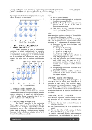
Fig. 10: Simulation Result for Existing FIR Filter
VI.
CONCLUSION
Low power consumption is the most
important criteria for the high performance DSP
system. High performance system can be achieved by
reduce its dynamic power that is the most important
part of total power dissipation. Power dissipation in
FIR filter has been much researched in recent years,
due to the importance of the multiplication and
addition arithmetic operation in wide are of DSP
system. The research work presented in this
dissertation has achieved good results and
demonstrated the efficiency of high level optimization
techniques. This report implements a high
performance FIR filter using low power adder and
multiplier. In this work we analyzed the different
adder and multiplier on basis of their dynamic power
dissipation. According to analysis result of adders and
multipliers, we achieved carry save adder and radix4
multiplier is consuming low power among all adder
and multiplier respectively. By using CSA and Radix
4 multiplier, we implemented the FIR filter and
analyzed its power consumption. The performance
curve of power dissipation by adders and multipliers
was derived form analysis of different adders and
multipliers. On the basis of power consumption result
of proposed and existing FIR filter. The conclusion
come out that proposed FIR filter is consume 10.36%
power lesser than existing FIR Filter. So, according to
result proposed FIR filter is the best for DSP system.
[6]
REFERENCES
[12]
[1]
[2]
Ankit Jairath, Sunil Kumar Shah, Amit Jain –
“Design & implementation of FPGA based
digital filters”, Journal of IJARCET, ISSN:
2278-1323, Vol. 1, Issue 7, Sept. 2012.
T Ramesh Reddy, Dr. K. Soundara Rajan –
“Low Power and Low Area Digital FIR filter
using Different Multipliers and Adders”,
International Journal of Engineering Research
www.ijera.com
[7]
[8]
[9]
[10]
[11]
[13]
www.ijera.com
and Technology (IJERT), ISSN: 2278-0181,
Vol.1, Issue 3, May-2012.
Shraddha S. Borkar and Awani S. Khobragade
– “Optimization of FIR Digital Filter using
Low Power MAC”, IJCSET, ISSN: 2231-0711,
Vol.2, Issue 4, 1150-1154, April-2012.
Prof. Gopal S. Gawande, Dr. K. B.
Khanchandani, T.P. Marode – “Approaches to
Design and Implement High Speed Low Power
Digital Filter: Review”, International Journal
of Computing and Corporate Research
(IJCCR), ISSN: 2249-054X, Vol. 2, Issue 1, 1
January 2012.
G.J.V.S.N. Lakshmi Devi and M. Ramesh
Kumar – “Design and Implementation of
Energy Efficient, Reconfigurable Fir filter
using Modified Booth and C.S.A.”, Journal of
Electrical and Electronics Engineering (JEEE),
ISSN: 2250-2424, Vol. 2, Issue 1, Sept 2012
11-18.
Shahnam Mirzari, Anup Hosangadi and Ryan
Kastner – “FPGA Implementation of High
Speed FIR Filter using Add and Shift Method”,
IEEE 2006.
M. Sree Divya And G. Kiran Kumar –
“Implementation of Low Power FIR Filter
Design based on Low Power Multiplier and
Adder”, International Conference on Electrical
and Electronics Engineering, ISBN: 978-9381693-85-8, 9 June 2012.
Manoj Garg, Dr. Rakesh Kumar Bansal & Dr.
Savina Bansal - “Reducing Power Dissipation
in FIR Filter: An Analysis”, Signal Processing:
An International Journal (SPIJ), Volume 4,
Issue 1.
M. Kathirvelu, T. Manigandan - “Design of
Low Power, High Speed FIR Filter with
Optimized PDP Adders and Flip-Flops for DSP
Applications”, European Journal of Scientific
Research, ISSN 1450-216X Vol.76 No.2
(2012), pp.214-225.
Tisserand - “Automatic generation of lowpower circuits for the evaluation of
polynomials”, in Proc. 40th Asilomar
Conference on Signals, Systems and
Computers. Pacific Grove, California, U.S.A.:
IEEE, Oct. 2006, pp. 20532057.
K.H. Tsoi, P.H.W. Leong - ”Mullet - a parallel
multiplier
generator”,
fpl, pp.691-694,
International
Conference
on
Field
Programmable Logic and Applications, 2005.
L. Ciminiera, P. Montuschi, ”Carry-Save
Multiplication
Schemes
Without
Final
Addition”, IEEE Transaction on Computer,
vol. 45, no. 9, Sep. 1996.
W. C. Yeh, and C. W. Jen, High-Speed Booth
Encoded Parallel Multiplier Design, IEEE
Transactions on Computers, vol. 49 (7), pp.
692-701, 2000.
181 | P a g e](https://image.slidesharecdn.com/ae4101177181-140130004132-phpapp01/85/Ae4101177181-5-320.jpg)

This research article discusses the implementation of a high-performance finite impulse response (FIR) filter using low power multipliers and adders, targeting improved performance in digital signal processing systems. It emphasizes the need for low power consumption and high throughput in portable systems and evaluates different multiplier and adder configurations to achieve these goals. The findings show that the proposed filter design achieves 10.36% lower power consumption compared to existing models.