Download to read offline


![ Full adders are used to
add 3 bit
Single bit and two bits
are forwarded to next
stage as it is
No of rows in per stages
ri+1 = 2[ri /3] + ri mod 3
If ri mod 3=0 then half
adder used
Modified Wallace 9-bit by 9-bit Reduction](https://image.slidesharecdn.com/6362fc2c-2943-4ace-a2e6-9aa9985e8442-170111052517/75/final8sem-22-2048.jpg)


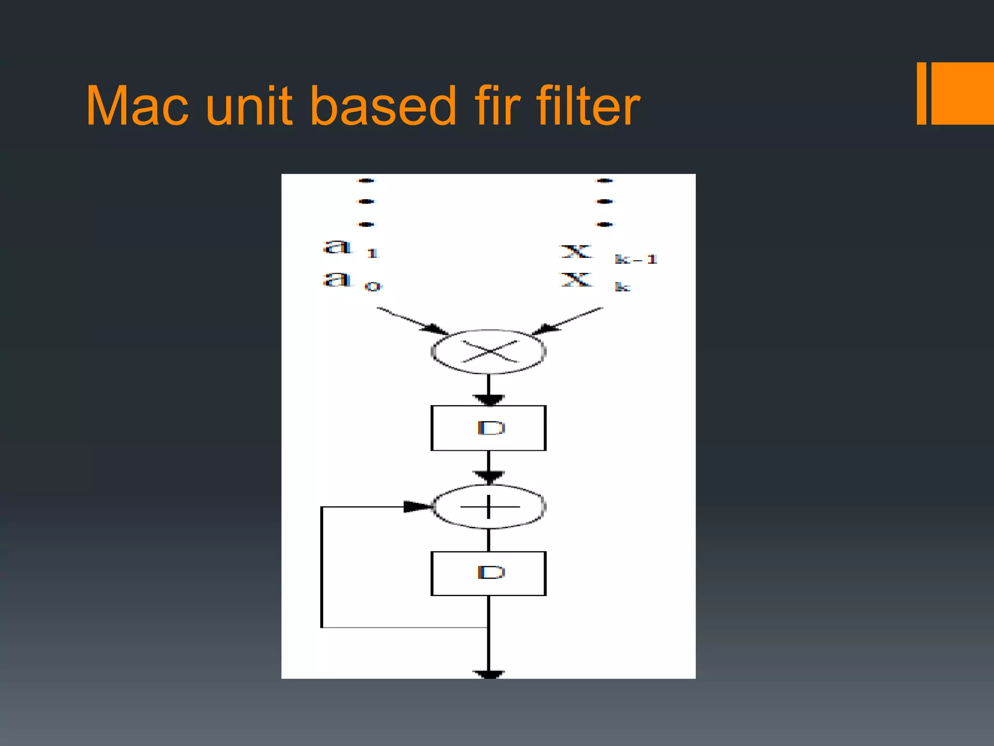


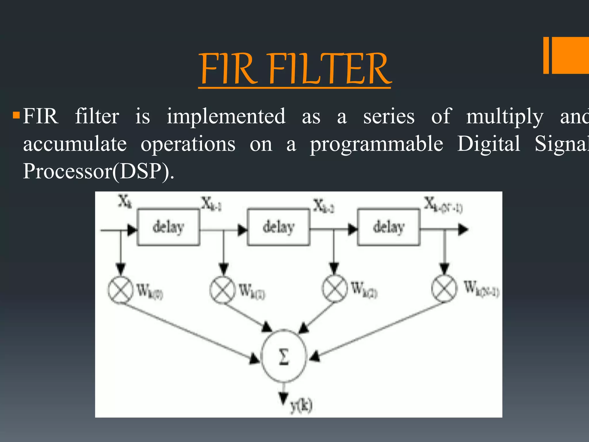
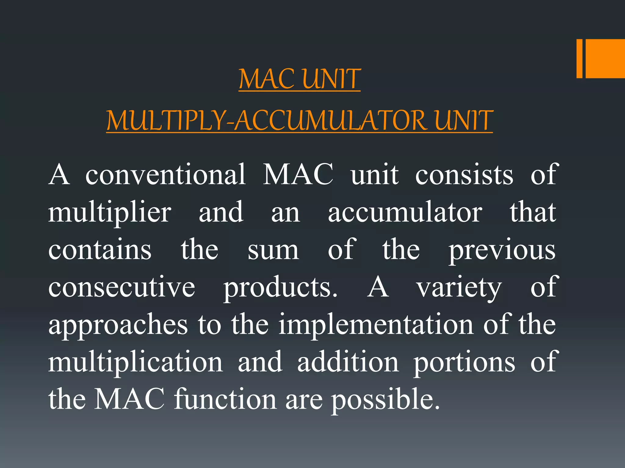
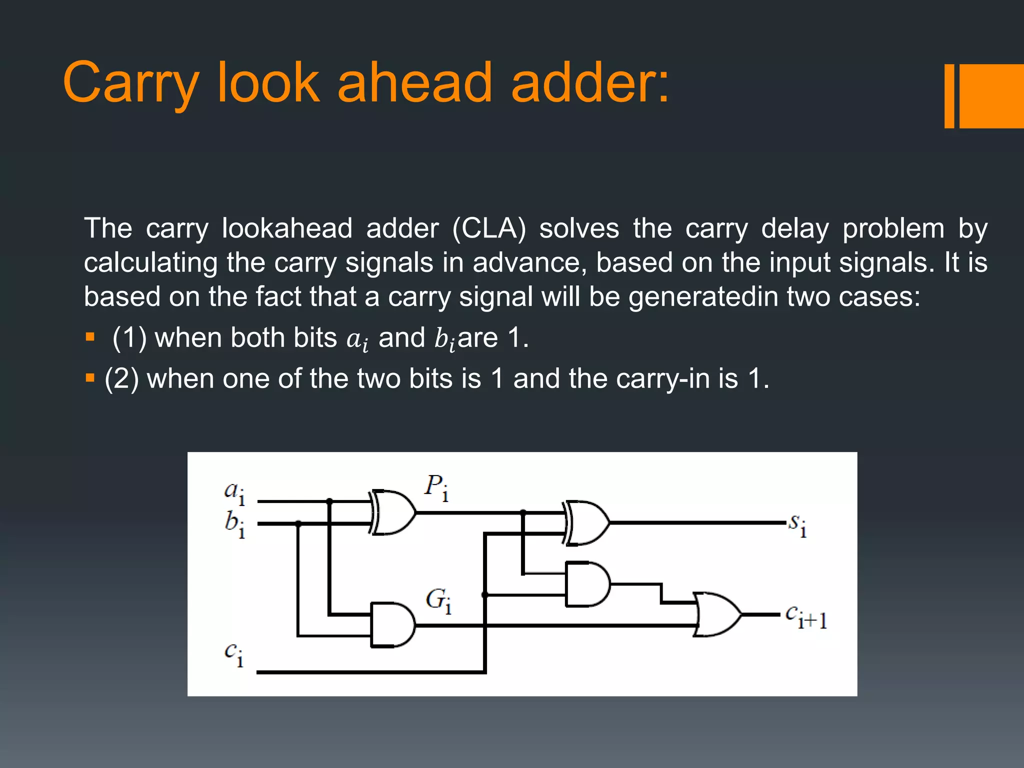
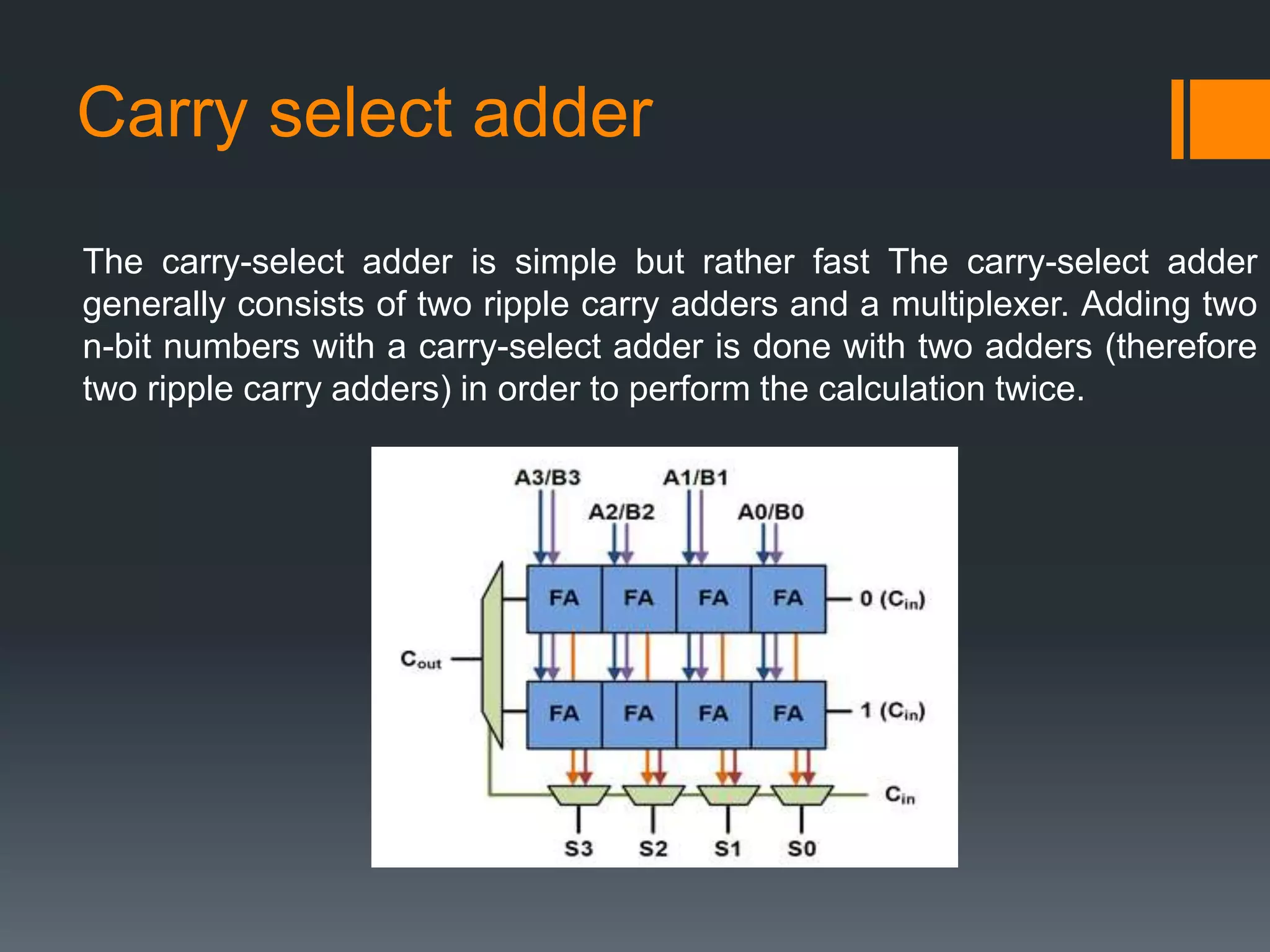
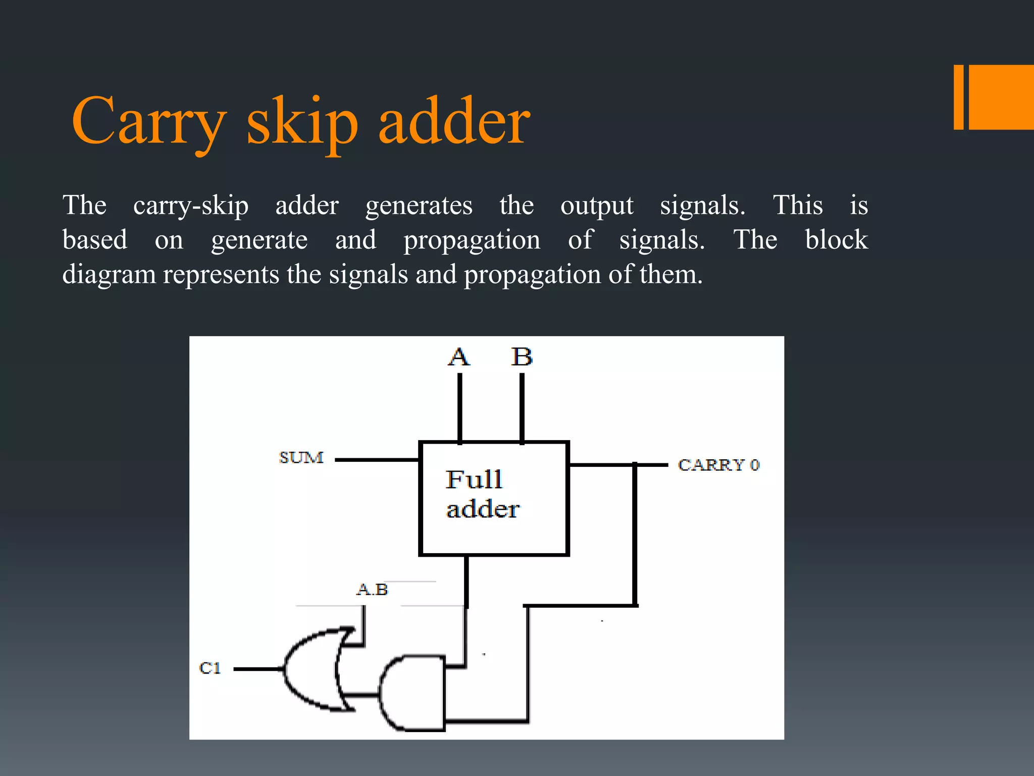
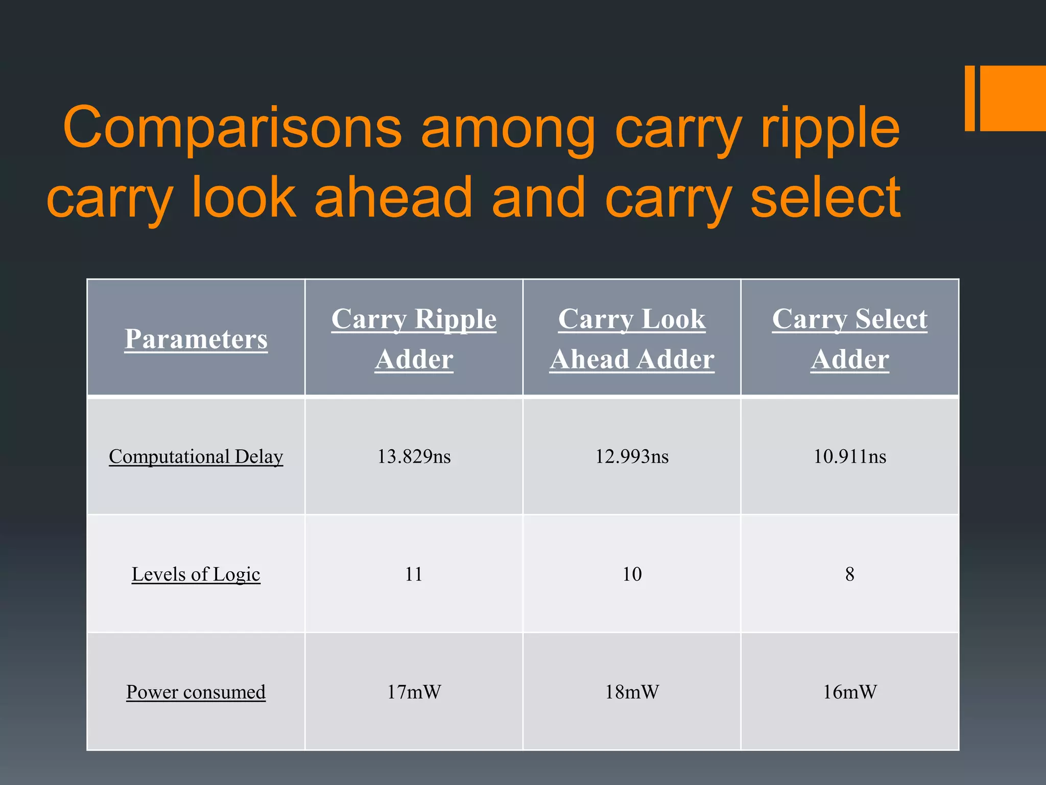
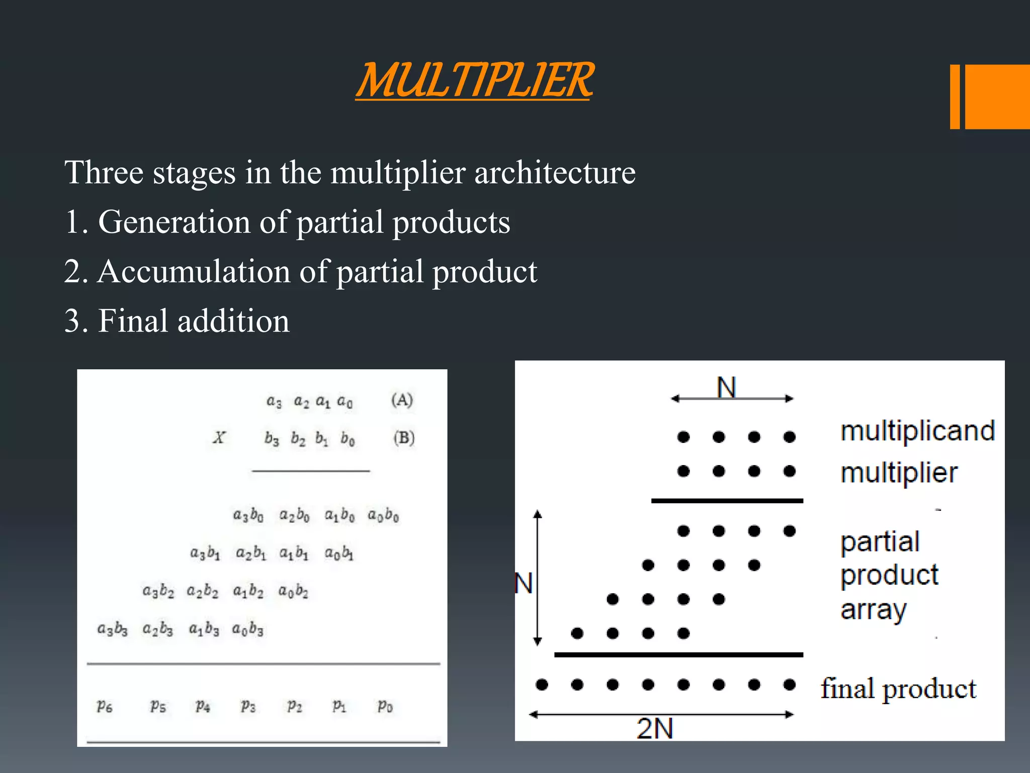
This document discusses optimization of a multiply-accumulate (MAC) unit for efficient finite impulse response (FIR) filter design. It analyzes different architectures for multipliers, adders, and MAC units. Direct form and transposed FIR filters are described along with MAC-based FIR filters using carry skip and carry select adders. Comparisons of power, speed and area are made between conventional and optimized designs. The aim is to design a more efficient FIR filter using optimized MAC unit architectures.


![CV Rana Riasat Ali[PDF]](https://cdn.slidesharecdn.com/ss_thumbnails/f370a1d7-fe39-491e-957e-f30727a31399-150729120624-lva1-app6892-thumbnail.jpg?width=640&height=640&fit=bounds)