Downloaded 134 times


![FIR FILTER
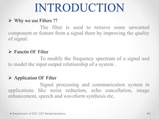
• The input- output relationship of FIR filter is given by
y(n) = 𝑘=0
𝑁−1
𝑎 𝑘 𝑥(𝑛 − 𝑘)
• x[n] and y [n] are the filter input and filter output
respectively
• a(k) ( k = 0,1,2,3……N-1) are the impulse response
coefficients of the filter.
• N is the filter length that is number of coefficients.
Department of ECE, CEC Benjanapadavu 8](https://image.slidesharecdn.com/boothmul-150508140556-lva1-app6892/85/Boothmultiplication-8-320.jpg)

![Department of ECE, CEC Benjanapadavu 25
[1] Ankit Jairath, Sunil Kumar Shah, Amit Jain – “Design & implementation of
FPGA based digital filters”, Journal of IJARCET, ISSN: 2278-1323, Vol. 1,
Issue 7, Sept.2012
[2] E. Ifeachor and B. Jervis, “Finite impulse response (FIR) filter design” in
Digital Signal Processing: A Practical Approach, 2nd ed., D. Kindersley,
Ed. South Asia: Pearson Education, 2002, pp. 342-440
[3] B. Rashidi, B. Rashidi and M. Pourormazd, “Design and Implementation of
Low Power Digital FIR Filter based on low power multipliers and adders
on Xilinx FPGA”, International Conference on Electronics Computer
Technology, 2011, pp.18- 22.
REFRENCES](https://image.slidesharecdn.com/boothmul-150508140556-lva1-app6892/85/Boothmultiplication-24-320.jpg)


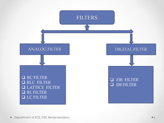
This document summarizes a presentation on modified Booth multipliers and FIR filters. It introduces Booth multiplication as an efficient algorithm for signed number multiplication. It then discusses FIR filters and their structure, noting that they require many multiplications. The Radix-2 and Radix-4 Booth multiplication algorithms are described in steps. Simulation results demonstrating the Radix-4 algorithm multiplying two numbers are shown. References on digital filter design and implementation are provided at the end.