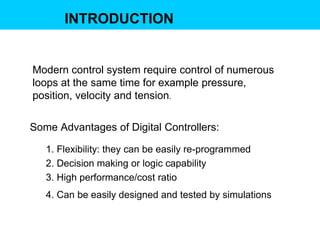
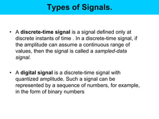
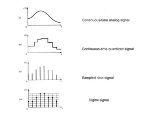
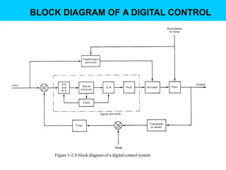
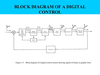
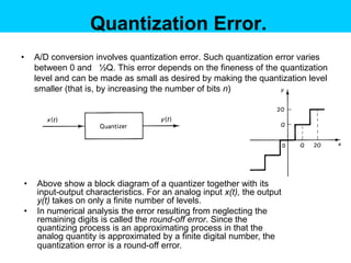
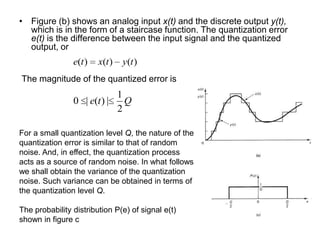
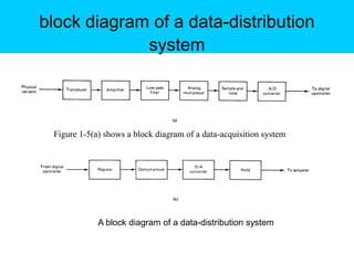
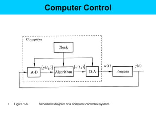
Digital Control
  (BER4113)
   Chapter 1
INTRODUCTION


Modern control system require control of numerous
loops at the same time for example pressure,
position, velocity and tension.

Some Advantages of Digital Controllers:

   1. Flexibility: they can be easily re-programmed
   2. Decision making or logic capability
   3. High performance/cost ratio
   4. Can be easily designed and tested by simulations
Types of Signals.

• A continuous-time signal is a signal defined over
  a continuous range of time. The amplitude may
  assume a continuous range of values or may assume
  only a finite number of distinct values The process of
  representing a variable by a set of distinct values is
  called quantization, and the resulting distinct values
  are called quantized values.


• An analog signal is a signal defined over a
  continuous range of time whose amplitude can
  assume a continuous range of values
Types of Signals.


• A discrete-time signal is a signal defined only at
  discrete instants of time . In a discrete-time signal, if
  the amplitude can assume a continuous range of
  values, then the signal is called a sampled-data
  signal.

• A digital signal is a discrete-time signal with
  quantized amplitude. Such a signal can be
  represented by a sequence of numbers, for example,
  in the form of binary numbers
Continuous-time analog signal


Continuous-time quantized signal


Sampled data signal


    Digital signal
BLOCK DIAGRAM OF A DIGITAL CONTROL


    Figure 1-2 A block diagram of a digital control system
BLOCK DIAGRAM OF A DIGITAL
         CONTROL


Figure 1-3 Block diagram of a digital control system showing signals in binary or graphic form
Definitions of Terms.

Sample-and-Hold (S/H).
• Term used for a sample-and-hold amplifier. It describes
  a circuit that receives an analog input signal and holds
  this signal at a constant value for a specified period of
  time.
Analog-to-Digital Converter (A/D).
• An analog-to-digital converter, also an encoder, is a
  device that converts an analog signal into a digital signal,
  usually a numerically coded signal. The conversion of an
  analog signal into the corresponding digital signal (binary
  number) is an approximation, because the analog signal
  can take on an infinite number of values, whereas the
  variety of different numbers that can be formed by a
  finite set of digits is limited. This approximation process
  is called quantization.
Digital-to-Analog Converter (D/A).
• A digital-to-analog converter, also called a decoder, is a
  device that converts a digital signal (numerically coded
  data) into an analog signal.
Plant or Process.
• A plant is any physical object to be controlled. Examples
  are a furnace, a chemical reactor, and a set of machine
  parts functioning together to perform a particular
  operation, such as a servo system or a spacecraft.
Transducer.
• A transducer is a device that converts an input signal
  into an output signal of another form, such as a device
  that converts a pressure signal into a voltage output.
  Transducers may be classified as analog transducers,
  sampled-data transducers, or digital transducers.
Quantizing and Quantization Error
 The process of representing a continuous or analog
  signal by a finite number of discrete states is called
  amplitude quantization.
 Quantizing means transforming a continuous or analog
  signal into a set of discrete states.
Quantizing.

The standard number system used for processing digital
signals is the binary number system. In this system the
code group consists of n pulses.
                                  The quantization level Q is
               FSR                defined as the range between
         Q                        two adjacent decision points
                2n


   FSR is the full-scale range
Leftmost bit of the natural binary code has the
most weight (one half of the FS) – called MSB
Rightmost bit has the least weight (1/2ⁿ times
the full scale) and is called the least significant
bit (LSB). Thus,

                    FSR
           LSB         n
                     2

 The least significant bit is the quantization
 level Q
Quantization Error.
•   A/D conversion involves quantization error. Such quantization error varies
    between 0 and ½Q. This error depends on the fineness of the quantization
    level and can be made as small as desired by making the quantization level
    smaller (that is, by increasing the number of bits n)


•   Above show a block diagram of a quantizer together with its
    input-output characteristics. For an analog input x(t), the output
    y(t) takes on only a finite number of levels.
•   In numerical analysis the error resulting from neglecting the
    remaining digits is called the round-off error. Since the
    quantizing process is an approximating process in that the
    analog quantity is approximated by a finite digital number, the
    quantization error is a round-off error.
• Figure (b) shows an analog input x(t) and the discrete output y(t),
  which is in the form of a staircase function. The quantization error
  e(t) is the difference between the input signal and the quantized
  output, or
                e(t )   x(t )   y(t )
The magnitude of the quantized error is
                            1
                0 | e(t ) |   Q
                            2

For a small quantization level Q, the nature of the
quantization error is similar to that of random
noise. And, in effect, the quantization process
acts as a source of random noise. In what follows
we shall obtain the variance of the quantization
noise. Such variance can be obtained in terms of
the quantization level Q.

The probability distribution P(e) of signal e(t)
shown in figure c
Data Acquisition, Conversion, And
       Distribution Systems

With the rapid growth in the use of digital computers to
perform digital control , both the data-acquisition system and
the distribution system have become an important part of the
entire control system. The signal conversion that takes place
in the digital control system involves the following operations:

 1. Multiplexing and demultiplexing
 2. Sample and hold.
 3. Analog-to-digital conversion (quantizing and
    encoding).
 4. Digital-to-analog conversion (decoding)
block diagram of a data-distribution
             system


 Figure 1-5(a) shows a block diagram of a data-acquisition system


             A block diagram of a data-distribution system
Computer Control

• Fig.1-6 - computer-controlled system.
• The output from the process y(t) is a continuous-time
  signal. The output is converted into digital form by the
  analog-to-digital (A-D) converter.
• The A-D converter can be included in the computer or
  regarded as a separate unit, according to one's
  preference. The conversion is done at the sampling
  times, tk. The computer interprets the converted signal,
  {y(tk)}, as a sequence of numbers, processes the
  measurements using an algorithm, and gives a new
  sequence of numbers, {u(tk)}.
Computer Control


•   Figure 1-6   Schematic diagram of a computer-controlled system.

Chapter1 slide

  • 1.
    Digital Control (BER4113) Chapter 1
  • 2.
    INTRODUCTION Modern control systemrequire control of numerous loops at the same time for example pressure, position, velocity and tension. Some Advantages of Digital Controllers: 1. Flexibility: they can be easily re-programmed 2. Decision making or logic capability 3. High performance/cost ratio 4. Can be easily designed and tested by simulations
  • 3.
    Types of Signals. •A continuous-time signal is a signal defined over a continuous range of time. The amplitude may assume a continuous range of values or may assume only a finite number of distinct values The process of representing a variable by a set of distinct values is called quantization, and the resulting distinct values are called quantized values. • An analog signal is a signal defined over a continuous range of time whose amplitude can assume a continuous range of values
  • 4.
    Types of Signals. •A discrete-time signal is a signal defined only at discrete instants of time . In a discrete-time signal, if the amplitude can assume a continuous range of values, then the signal is called a sampled-data signal. • A digital signal is a discrete-time signal with quantized amplitude. Such a signal can be represented by a sequence of numbers, for example, in the form of binary numbers
  • 5.
    Continuous-time analog signal Continuous-timequantized signal Sampled data signal Digital signal
  • 6.
    BLOCK DIAGRAM OFA DIGITAL CONTROL Figure 1-2 A block diagram of a digital control system
  • 7.
    BLOCK DIAGRAM OFA DIGITAL CONTROL Figure 1-3 Block diagram of a digital control system showing signals in binary or graphic form
  • 8.
    Definitions of Terms. Sample-and-Hold(S/H). • Term used for a sample-and-hold amplifier. It describes a circuit that receives an analog input signal and holds this signal at a constant value for a specified period of time. Analog-to-Digital Converter (A/D). • An analog-to-digital converter, also an encoder, is a device that converts an analog signal into a digital signal, usually a numerically coded signal. The conversion of an analog signal into the corresponding digital signal (binary number) is an approximation, because the analog signal can take on an infinite number of values, whereas the variety of different numbers that can be formed by a finite set of digits is limited. This approximation process is called quantization.
  • 9.
    Digital-to-Analog Converter (D/A). •A digital-to-analog converter, also called a decoder, is a device that converts a digital signal (numerically coded data) into an analog signal. Plant or Process. • A plant is any physical object to be controlled. Examples are a furnace, a chemical reactor, and a set of machine parts functioning together to perform a particular operation, such as a servo system or a spacecraft. Transducer. • A transducer is a device that converts an input signal into an output signal of another form, such as a device that converts a pressure signal into a voltage output. Transducers may be classified as analog transducers, sampled-data transducers, or digital transducers.
  • 10.
    Quantizing and QuantizationError  The process of representing a continuous or analog signal by a finite number of discrete states is called amplitude quantization.  Quantizing means transforming a continuous or analog signal into a set of discrete states.
  • 11.
    Quantizing. The standard numbersystem used for processing digital signals is the binary number system. In this system the code group consists of n pulses. The quantization level Q is FSR defined as the range between Q two adjacent decision points 2n FSR is the full-scale range
  • 12.
    Leftmost bit ofthe natural binary code has the most weight (one half of the FS) – called MSB Rightmost bit has the least weight (1/2ⁿ times the full scale) and is called the least significant bit (LSB). Thus, FSR LSB n 2 The least significant bit is the quantization level Q
  • 13.
    Quantization Error. • A/D conversion involves quantization error. Such quantization error varies between 0 and ½Q. This error depends on the fineness of the quantization level and can be made as small as desired by making the quantization level smaller (that is, by increasing the number of bits n) • Above show a block diagram of a quantizer together with its input-output characteristics. For an analog input x(t), the output y(t) takes on only a finite number of levels. • In numerical analysis the error resulting from neglecting the remaining digits is called the round-off error. Since the quantizing process is an approximating process in that the analog quantity is approximated by a finite digital number, the quantization error is a round-off error.
  • 14.
    • Figure (b)shows an analog input x(t) and the discrete output y(t), which is in the form of a staircase function. The quantization error e(t) is the difference between the input signal and the quantized output, or e(t ) x(t ) y(t ) The magnitude of the quantized error is 1 0 | e(t ) | Q 2 For a small quantization level Q, the nature of the quantization error is similar to that of random noise. And, in effect, the quantization process acts as a source of random noise. In what follows we shall obtain the variance of the quantization noise. Such variance can be obtained in terms of the quantization level Q. The probability distribution P(e) of signal e(t) shown in figure c
  • 15.
    Data Acquisition, Conversion,And Distribution Systems With the rapid growth in the use of digital computers to perform digital control , both the data-acquisition system and the distribution system have become an important part of the entire control system. The signal conversion that takes place in the digital control system involves the following operations: 1. Multiplexing and demultiplexing 2. Sample and hold. 3. Analog-to-digital conversion (quantizing and encoding). 4. Digital-to-analog conversion (decoding)
  • 16.
    block diagram ofa data-distribution system Figure 1-5(a) shows a block diagram of a data-acquisition system A block diagram of a data-distribution system
  • 17.
    Computer Control • Fig.1-6- computer-controlled system. • The output from the process y(t) is a continuous-time signal. The output is converted into digital form by the analog-to-digital (A-D) converter. • The A-D converter can be included in the computer or regarded as a separate unit, according to one's preference. The conversion is done at the sampling times, tk. The computer interprets the converted signal, {y(tk)}, as a sequence of numbers, processes the measurements using an algorithm, and gives a new sequence of numbers, {u(tk)}.
  • 18.
    Computer Control • Figure 1-6 Schematic diagram of a computer-controlled system.