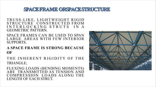
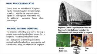
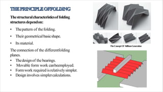
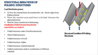
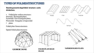
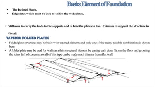
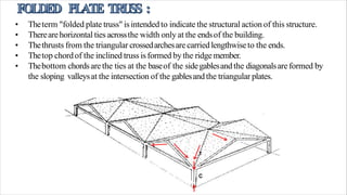
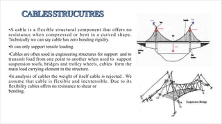
Space frames are rigid, lightweight structures constructed from interlocking struts arranged in geometric patterns. They can span large areas with few interior supports due to their inherent rigidity from triangular formations that transmit loads as tension and compression. Folded plate structures are assemblies of rigidly connected flat plates that can carry loads without interior beams. They were first used in 1923 for an aircraft hangar roof in Paris and take inspiration from structures in nature like tree leaves. Cable structures have cables as their primary load-bearing elements and are often used in bridges and roofs to transmit loads between supports.
Construction method of steel structure space frame .pptx
Advance structural system
1.
2. TRUSS-LIKE, LIGHTWEIGHT RIGID
STRUCTURE CONSTRUCTED FROM
I N T E R L O C K I N G S T R U T S I N A
GEOMETRIC PATTERN.
SPACE FRAMES CAN BE USED TO SPAN
LARGE AREAS WITH FEW INTERIOR
SUPPORTS.
A SPACE FRAME IS STRONG BECAUSE
OF
T H E I N H E R E N T R I G I D I T Y O F T H E
TRIANGLE;
FLEXING LOADS (BENDING MOMENTS)
ARE TRANSMITTED AS TENSION AND
COMPRESSION LOADS ALONG THE
LENGTH OF EACH STRUT.
3. Folded plates are assemblies of flatplates
rigidly connected together along their edges
in sucha
capable of
way that the structural system
carrying loads without the need
for additional supporting beams along
mutualedges.
EngineerEudeneFreyssinetperformed the
first roof with thefolded structure in
1923asanaircraft hangarat OrlyAirport
inParis.
The principle of folding as a tool to develop a
general structural shape has been known for a
long time. Folded structure systems which
are analogousto several biological systems
such as found at broadleaf-tree leaves, petals and
foldable insect wings, are adopted to be employed.
Leafof
PalmTree
Beetle
InsectWit
h
Foldable
Wings
Seas
hel
4. Thestructuralcharacteristicsof folding
structuresdependon:
• Thepattern of thefolding.
• Their geometrical basicshape.
• Its material.
The connection of the differentfolding
planes.
• Thedesignof the bearings.
• Movable form work canbeemployed.
• Formwork required isrelativelysimpler.
• Design involves simplercalculations.
TheConceptOf StiffnessGeneration
5. StructuralConditionOfFolding
Structures
LoadDistributionprocess:
At first, the external forces are transferredto the shorter edgeofone
folding element.
There, the reaction asan axial force is divided between the
adjacentelements.
Then the forces transferred tothebearings.
Classificationoffoldedstructuresbasedonthe
materialtheyaremadeof:
• Folded structures made ofreinforcedconcrete
• Metal foldedstructures
• Folded structures ofwood
• Folded structures ofglass
• Folded structures of plasticmaterials
• Folded constructions made in combination of different
materials
7. • TheInclinedPlates.
• Edgeplateswhich must beusedto stiffen the wideplates,
• Stiffenersto carrythe loadsto the supportsandto hold the platesin line. Columnsto supportthe structure in
the air.
• Folded plate structures may be built with tapered elements and only one of the many possible combinationsis shown
here.
• Afolded plate may be used for walls as a thin structural element by casting each plate flat on the floor and grouting
the jointsfull of concrete.awall of this typecanbemademuchthinner thanaflat wall.
T
C
8. • Theterm "folded plate truss" isintended to indicate the structural actionof this structure.
• Therearehorizontal ties acrossthe width only at the endsof the building.
• Thethrusts from the triangular crossedarchesare carriedlengthwiseto the ends.
• Thetop chordof the inclined truss isformed bythe ridgemember.
• Thebottom chordsare the ties at the baseof the sidegablesandthe diagonalsareformed by
the sloping valleysat the intersection of the gablesandthe triangular plates.
C
9. • Anarchwith straight segmentsissometimescalledaRigidFrame.
• It isnot asefficient asthe curved archbecausethebending moments aregreater.
• Tiesacrossthe plates arerequired at the kneesandat the crown in order to distribute the forces
at the endsof eachsegment.
10. • Theusualupturned edgeplate canbeeliminated andthe roof structure canbemadeto appear
very thin if the edgeplate isreplacedby aseriesof columns.
• Theslabbetween columns must be designedasabeamandit maybe convenient to extend the
main roofslabasa CantileverCanopy.
• Thebeamelement that carries the load of the roof between columns will then be wider and
windows under the slabwill havethe samefunction asin the previous examplesof folded
plates.
11. • In this structure the walls are of tilt-up concrete construction; concrete is cast flat on the floor
and raised into place by cranes.
• The walls are designed to be continuous with the roof plates. Tilt-up walls usually are joined by
poured-in-place columns. in this design, columns are not necessary at the junction of the
individual sidewall panelsbecausethe walls arebracedat the top.
• Only a simple grouted key slot is provided. The tilt-up panels can serve as theirown
foundation walls so only a
continuousfooting padisusedwith anotch to receivethe tilt-up
12. •The size of the frames may be reduced by using a steel tie between the tops of the columns
which canbe concealedin the fenestration. Thedimensionsof the plates aredependent on both the
width of the barrel and on the span.
• The depth of the shell should be about 0.10 times the span and the maximum slope of a plate
should not be greater than 40degrees.
• Forexample,assumefor the above structure that the spanis 60 feet and the baywidth is 24 feet.
the depth of the shell should be about 6 feet and the horizontal width of each plate with a
three segment plate should be about 8feet.
• the slope of the plates is 6/8, which is about 37 degrees and is satisfactory. the thickness of the
plates could be about 3 ½inches.
13. Shell is a type of building enclosures.
Shells belong to the family of arches . They can be defined as curved or angled structures capable of
transmitting loads in more than two directions to supports.
Ashell with one curved surface is known as a vault (single curvature ).
A shell with doubly curved surface is known as a dome (doublecurvature).
14. There are many different ways to classify shell structures but two ways arecommon:
• 1. The material which the shell is made of: like reinforced concrete, plywood or steel, becauseeach
one has different properties that can determine the shape of the building and therefore, these
characteristics have to be considered in the design.
• 2. The shell thickness: shells can be thick or thin.
15. • The thin concrete shell structures are a lightweight construction composed of a relatively thin shell
made of reinforced concrete, usually without the use of internal supports giving an open unobstructed
interior. The shells are most commonly domes and flat plates, but may also take the form of ellipsoids
or cylindrical sections, or some combination thereof. Most concrete shell structures are commercial
and sports buildings or storage facilities.
TypesofThinConcreteShells
1. Barrels shells
• The cylindrical thin shells, also called barrels, should not be confused with the vaults even with the huge
similarity in the shape of both structures, because each of these structures has a different structural behavior as
well as different requirements in the minimum thickness and the shape.
2. Folded plate
• A thin-walled building structure of the shell type.
16.
17. • A Hypar is a surface curved in two directions that can be designed as a shell orwarped
lattice.
• A hypar is triangular, rectangular or rhomboidal in plan, with corners raised to the elevation
desired for use and/or appearance. The edges of Hypars are typically restrained by stiffhollow
beams that collect & transfer roof loads to the foundations.
18. • A rounded roof, with a circular base, shaped like an arch in all
directions.. First used in much of the Middle East and North
Africa whence it spread to other parts of the Islamic world,
because of its distinctive form the dome has, like the minaret,
become a symbol of Islamic architecture.
• Dome has double curvature and the resulting structure is much
stiffer and stronger than a single curved surface, such as a
barrel shell.
19. • A translation shell is a dome set on four arches.The shape is different from a spherical dome
and is generated by a vertical circle moving on another circle. All vertical slices have the
same radius. It is easier to form than a spherical dome.
20. •A cable is a flexible structural component that offers no
resistance when compressed or bent in a curved shape.
Technically we can say cable has zero bending rigidity.
•It can only support tensile loading.
•Cables are often used in engineering structures for support and to
transmit load from one point to another when used to support
suspension roofs, bridges and trolley wheels, cables form the
main load carrying element in the structure.
•In analysis of cables the weight of itself cable is rejected . We
assume that cable is flexible and inextensible. Due to its
flexibility cables offers no resistance to shear or
bending.
21. • Lateral bracing
• Suspended highrise structures (tensile columns)
• Single-layer, simply suspended cable roofs
• Single-curvature and dish-shaped (synclastic) hanging
roofs
• Prestressed tensile membranes and cable nets (see Surface
Structures)
• Edge-supported saddle roofs
• Mast-supported conical saddle roofs
• Arch-supported saddle roofs
• Air supported structures and air-inflated
structures (air members)
Cable-supported structures cable-supported beams and
arched beams cable-stayed bridges
cable-stayed roof structures
Tensegrity structures
Planar open and closed tensegrity systems: cable beams,
cable trusses, cable frames
Spatial open tensegrity systems: cable domes
Spatial closed tensegrity systems: polyhedral twist units
Hybrid structures
Combination of the above systems
22. • Simply suspended or hanging roofs include cable roofs of
single curvature and synclastic shape, that is cylindrical
roofs with parallel cable arrangement, and polygonal
dishes with radial cable pattern or cable nets.
• The simply suspended cables may be of the singleplane,
double-flange, or double-layer type.
• The concept of simply suspended roofs has surely been
influenced by suspension bridge construction.
• Most buildings using the suspended roof concept are either
rectangular or round; in other words, the cable arrangement
is either parallel or radial.
• However, in free-form buildings, the roof geometry is not a
simple inverted cylinder or dish and the cable layout is
irregular.
23. • In the typical suspended roof the cables (or other member types such as W-sections, metal sheets,
prestressed concrete strips) are integrated with the roof structure. Here, one distinguishes whether
single- or double-layer cable systems are used. Simple, single-layer, suspended cable roofs must be
stabilized by heavyweight or rigid members. Sometimes, prestressed suspended concrete shells are
used where during erection they act as simple suspended cable systems, while in the final statethey
behave like inverted prestressed concrete shells. In simple, double-layer cable structures, such as
the typical bicycle wheel roof, stability is achieved by secondary cables prestressing the main
suspended cables.
24. • Suspended roofs with simple curvature behave
l i k e a g r o u p o f c a b l e s s u s p e n d e d i n
parallel.each cable deforms under its own load,
independently of its neighbours.
• Curved roofs of this kind have also been cast in
concrete. The result is a simply curved
suspended shell.
• Such simply curved concrete shells, for this is
how they act ratherc than as suspended roofs,
are relatively heavy, whereas the chance of
achieving lightness is the most attractive thing
about a genuine cable structure.
25.
26. There are generally two types of cables
structures.
1- Suspension type Cables.
2- Stayed type Cables.
Golden Gate Bridge
San Francisco
Akashi Kaikyo
Suspension Bridge
27.
28.
29. • A cable-stayed bridge consists of one or more piers, with cables suppoting the bridge deck.
• Basic idea: reduce the span of the beam (deck) several times compared to clear span
between the piers.
• steel cables-stayed bridges are regarded as the most economical bridge for
spans ranging between between 20 and 400m
• shorter spans: truss or box girder bridges
• larger spans: suspension bridges
30. Under-deck cable-stayed bridges and combined cable-stayed
bridges are two innovative and efficient types of cable-stayed
bridges. In under-deck cable- stayed bridges, the stay cables are
located under the deck where they are deviated by one or more
struts and are then self-anchored into the deck. On the other
hand, in combined cable-stayed bridges the stay cables are
located both above and below the deck, deviated by pylons and
struts before being self anchored into the deck.