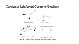
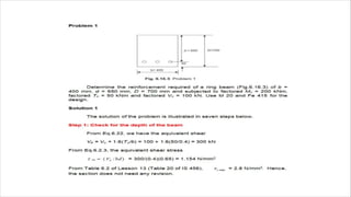
• Instruction Objectives:
• At the end of this lesson, the student should be able to:
• identify the beams and frames subjected to torsion,name and explain the two types
of torsion,state the basis of approach of design for combined bending, shear and
torsion as per IS 456,select the critical section for the design, determine the
equivalent shear and moment from the given factored bending moment, shear and
torsional moment.
define equivalent nominal shear stress,state when do we provide minimum shear
reinforcement in beams subjected to combined bending moment, shear and torsional
moment,state when do we provide both longitudinal and transverse reinforcement in
beams subjected to combined bending moment, shear and torsional moment,state
when do we provide tensile, compressive and side face reinforcement, respectively,
in beams subjected to combined bending shear and torsional moment,design the
beams subjected to combined bending, shear and torsional moment as per IS 456.
• the presence of torsional moment along with bending moment and shear in
reinforced concrete members with specific examples. The approach of design of
such beams has been explained mentioning the critical section to be designed.
Expressing the equivalent shear and bending moment, this lesson illustrates the
step by step design procedure of beam under combined bending, shear and torsion.
The requirements of IS 456 regarding the design are also explained. Numerical
problems have been solved to explain the design of beams under combined
bending, shear and torsion.
• On several situations beams and slabs are subjected to torsion in addition to
bending moment and shear force. Loads acting normal to the plane of bending will
cause bending moment and shear force.
• However, loads away from the plane of bending will induce torsional moment
along with bending moment and shear. Space frames (Fig.6.16.1a), inverted L-
beams as in supporting sunshades and canopies (Fig.6.16.1b), beams curved in
plan (Fig.6.16.1c), edge beams of slabs (Fig.6.16.1d) are some of the examples
where torsional moments are also present.
• Skew bending theory, space-truss analogy are some of the theories developed to
understand the behaviour of reinforced concrete under torsion combined with
bending moment and shear. These torsional moments are of two types:
• (i)Primary or equilibrium torsion, and
• (ii)Secondary or compatibility torsion.
• The primary torsion is required for the basic static equilibrium of most of the
statically determinate structures. Accordingly, this torsional moment must be
considered in the design as it is a major component.
• The secondary torsion is required to satisfy the compatibility condition between
members. However, statically indeterminate structures may have any of the two
types of torsions.
• Minor torsional effects may be ignored in statically indeterminate structures due to
the advantage of having more than one load path for the distribution of loads to
maintain the equilibrium.
• This may produce minor cracks without causing failure. However, torsional
moments should be taken into account in the statically indeterminate structures if
they are of equilibrium type and where the torsional stiffness of the members has
been considered in the structural analysis.
• It is worth mentioning that torsion must be considered in structures subjected to
unsymmetrical loadings about axes.
• Clause 41 of IS 456 stipulates the above stating that, "In structures, where torsion
is required to maintain equilibrium, members shall be designed for torsion in
accordance with 41.2, 41.3 and 41.4. However, for such indeterminate structures
where torsion can be eliminated by releasing redundant restraints, no specific
design for torsion is necessary, provided torsional stiffness is neglected in the
calculation of internal forces. Adequate control of any torsional cracking is
provided by the shear reinforcement as per cl. 40".
• The behaviour of members under the effects of combined bending, shear and
torsion is still a subject of extensive research.
• We know that the bending moments are distributed among the sharing members
with the corresponding distribution factors proportional to their bending stiffness
EI/L where E is the elastic constant, I is the moment of inertia and L is the
effective span of the respective members. In a similar manner, the torsional
moments are also distributed among the sharing members with the corresponding
distribution factors proportional to their torsional stiffness GJ/L, where G is the
elastic shear modulus, J is polar moment of inertia and L is the effective span
(or length) of the respective members.
• The exact analysis of reinforced concrete members subjected to torsional moments
combined with bending moments and shear forces is beyond the scope here.
However, the codal provisions of designing such members are discussed below.
• As per the stipulations of IS 456, the longitudinal and transverse reinforcements
are determined taking into account the combined effects of bending moment, shear
force and torsional moment. Two impirical relations of equivalent shear and
equivalent bending moment are given. These fictitious shear force and bending
moment, designated as equivalent shear and equivalent bending moment, are
separate functions of actual shear and torsion, and actual bending moment and
torsion, respectively.
• The total vertical reinforcement is designed to resist the equivalent shear Ve and
the longitudinal reinforcement is designed to resist the equivalent bending moment
Me1 and Me2, as explained in secs. 6.16.6 and 6.16.7, respectively.
• These design rules are applicable to beams of solid rectangular cross-section.
However, they may be applied to flanged beams by substituting bw for b. IS 456
further suggests to refer to specialist literature for the flanged beams as the design
adopting the code procedure is generally conservative.
As per cl. 41.2 of IS 456, sections located less than a distance d from the face of the
support is to be designed for the same torsion as computed at a distance d, where d
is the effective depth of the beam.
Shear and Torsion
(a)
The equivalent shear, a function of the actual shear and torsional moment is
determined from the following impirical relation:
• Ve = Vu + 1.6(Tu/b)
• (6.22)
• where Ve = equivalent shear,
• Vu = actual shear,
• Tu = actual torsional moment,
• b = breadth of beam.
• Me2 = Mt - Mu
• The Me2 will be considered as acting
in the opposite sense to the moment
Mu.
• The maximum area of compression reinforcement shall not exceed 0.04
• bD. They shall be enclosed by stirrups for effective lateral restraint.
• (c)Side face reinforcement (cls. 26.5.1.3 and 26.5.1.7b)
• Beams exceeding the depth of 750 mm and subjected to bending moment and shear shall have side face
reinforcement. However, if the beams are having torsional moment also, the side face reinforcement shall be
provided for the overall depth exceeding 450 mm. The total area of side face reinforcement shall be at least
0.1 per cent of the web area and shall be distributed equally on two faces at a spacing not exceeding 300 mm
or web thickness, whichever is less.
Thank you
Mr. VIKAS MEHTA
School of Mechanical and civil engineering
Shoolini University
Village Bajhol, Solan (H.P)
vikasmehta@shooliniuniversity.com
+91 9459268898

Torsion in beam

  • 2.
    • Instruction Objectives: •At the end of this lesson, the student should be able to: • identify the beams and frames subjected to torsion,name and explain the two types of torsion,state the basis of approach of design for combined bending, shear and torsion as per IS 456,select the critical section for the design, determine the equivalent shear and moment from the given factored bending moment, shear and torsional moment.
  • 3.
    define equivalent nominalshear stress,state when do we provide minimum shear reinforcement in beams subjected to combined bending moment, shear and torsional moment,state when do we provide both longitudinal and transverse reinforcement in beams subjected to combined bending moment, shear and torsional moment,state when do we provide tensile, compressive and side face reinforcement, respectively, in beams subjected to combined bending shear and torsional moment,design the beams subjected to combined bending, shear and torsional moment as per IS 456.
  • 4.
    • the presenceof torsional moment along with bending moment and shear in reinforced concrete members with specific examples. The approach of design of such beams has been explained mentioning the critical section to be designed. Expressing the equivalent shear and bending moment, this lesson illustrates the step by step design procedure of beam under combined bending, shear and torsion. The requirements of IS 456 regarding the design are also explained. Numerical problems have been solved to explain the design of beams under combined bending, shear and torsion.
  • 6.
    • On severalsituations beams and slabs are subjected to torsion in addition to bending moment and shear force. Loads acting normal to the plane of bending will cause bending moment and shear force. • However, loads away from the plane of bending will induce torsional moment along with bending moment and shear. Space frames (Fig.6.16.1a), inverted L- beams as in supporting sunshades and canopies (Fig.6.16.1b), beams curved in plan (Fig.6.16.1c), edge beams of slabs (Fig.6.16.1d) are some of the examples where torsional moments are also present. • Skew bending theory, space-truss analogy are some of the theories developed to understand the behaviour of reinforced concrete under torsion combined with bending moment and shear. These torsional moments are of two types: • (i)Primary or equilibrium torsion, and • (ii)Secondary or compatibility torsion.
  • 7.
    • The primarytorsion is required for the basic static equilibrium of most of the statically determinate structures. Accordingly, this torsional moment must be considered in the design as it is a major component. • The secondary torsion is required to satisfy the compatibility condition between members. However, statically indeterminate structures may have any of the two types of torsions. • Minor torsional effects may be ignored in statically indeterminate structures due to the advantage of having more than one load path for the distribution of loads to maintain the equilibrium. • This may produce minor cracks without causing failure. However, torsional moments should be taken into account in the statically indeterminate structures if they are of equilibrium type and where the torsional stiffness of the members has been considered in the structural analysis. • It is worth mentioning that torsion must be considered in structures subjected to unsymmetrical loadings about axes.
  • 8.
    • Clause 41of IS 456 stipulates the above stating that, "In structures, where torsion is required to maintain equilibrium, members shall be designed for torsion in accordance with 41.2, 41.3 and 41.4. However, for such indeterminate structures where torsion can be eliminated by releasing redundant restraints, no specific design for torsion is necessary, provided torsional stiffness is neglected in the calculation of internal forces. Adequate control of any torsional cracking is provided by the shear reinforcement as per cl. 40".
  • 9.
    • The behaviourof members under the effects of combined bending, shear and torsion is still a subject of extensive research. • We know that the bending moments are distributed among the sharing members with the corresponding distribution factors proportional to their bending stiffness EI/L where E is the elastic constant, I is the moment of inertia and L is the effective span of the respective members. In a similar manner, the torsional moments are also distributed among the sharing members with the corresponding distribution factors proportional to their torsional stiffness GJ/L, where G is the elastic shear modulus, J is polar moment of inertia and L is the effective span (or length) of the respective members. • The exact analysis of reinforced concrete members subjected to torsional moments combined with bending moments and shear forces is beyond the scope here. However, the codal provisions of designing such members are discussed below.
  • 10.
    • As perthe stipulations of IS 456, the longitudinal and transverse reinforcements are determined taking into account the combined effects of bending moment, shear force and torsional moment. Two impirical relations of equivalent shear and equivalent bending moment are given. These fictitious shear force and bending moment, designated as equivalent shear and equivalent bending moment, are separate functions of actual shear and torsion, and actual bending moment and torsion, respectively.
  • 11.
    • The totalvertical reinforcement is designed to resist the equivalent shear Ve and the longitudinal reinforcement is designed to resist the equivalent bending moment Me1 and Me2, as explained in secs. 6.16.6 and 6.16.7, respectively. • These design rules are applicable to beams of solid rectangular cross-section. However, they may be applied to flanged beams by substituting bw for b. IS 456 further suggests to refer to specialist literature for the flanged beams as the design adopting the code procedure is generally conservative.
  • 12.
    As per cl.41.2 of IS 456, sections located less than a distance d from the face of the support is to be designed for the same torsion as computed at a distance d, where d is the effective depth of the beam. Shear and Torsion
  • 13.
    (a) The equivalent shear,a function of the actual shear and torsional moment is determined from the following impirical relation: • Ve = Vu + 1.6(Tu/b) • (6.22) • where Ve = equivalent shear, • Vu = actual shear, • Tu = actual torsional moment, • b = breadth of beam.
  • 16.
    • Me2 =Mt - Mu • The Me2 will be considered as acting in the opposite sense to the moment Mu.
  • 19.
    • The maximumarea of compression reinforcement shall not exceed 0.04 • bD. They shall be enclosed by stirrups for effective lateral restraint. • (c)Side face reinforcement (cls. 26.5.1.3 and 26.5.1.7b) • Beams exceeding the depth of 750 mm and subjected to bending moment and shear shall have side face reinforcement. However, if the beams are having torsional moment also, the side face reinforcement shall be provided for the overall depth exceeding 450 mm. The total area of side face reinforcement shall be at least 0.1 per cent of the web area and shall be distributed equally on two faces at a spacing not exceeding 300 mm or web thickness, whichever is less.
  • 26.
    Thank you Mr. VIKASMEHTA School of Mechanical and civil engineering Shoolini University Village Bajhol, Solan (H.P) vikasmehta@shooliniuniversity.com +91 9459268898