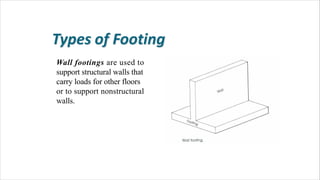
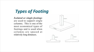
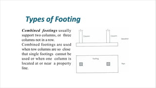
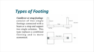
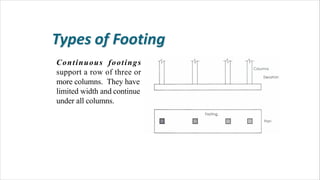
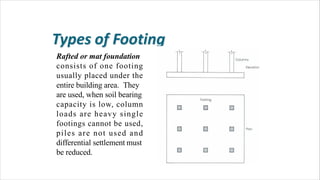
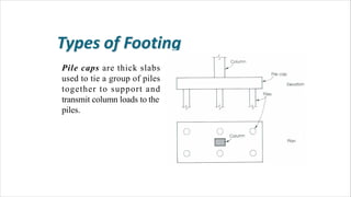
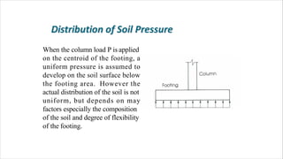
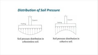
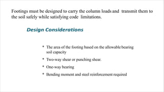
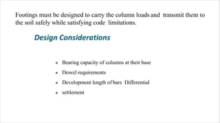
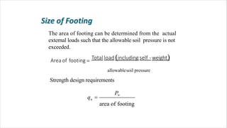
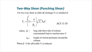
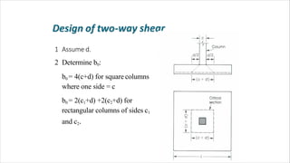
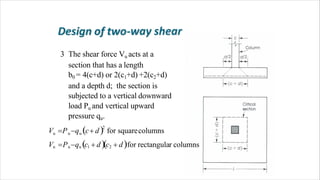
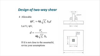
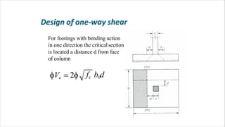
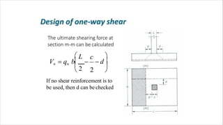
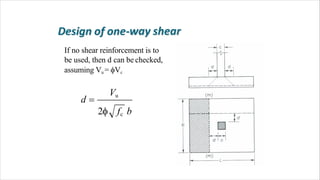
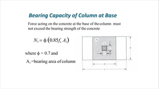
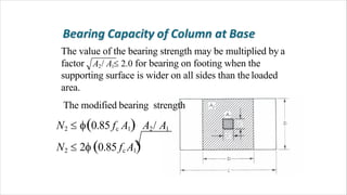
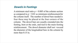
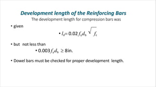
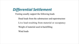
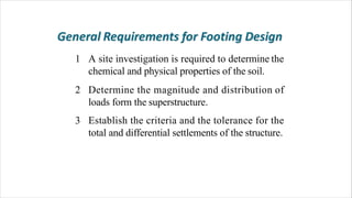
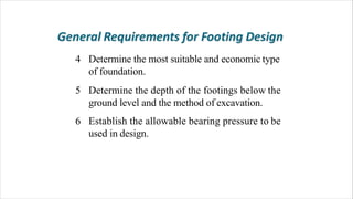
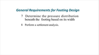
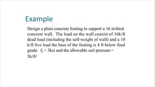
Definition
Footings are structural members used to support
columns and walls and to transmit and distribute
their loads to the soil in such a way that the load
bearing capacity of the soil is not exceeded,
excessive settlement, differential settlement,or
rotation are prevented and adequate safety
against overturning or sliding is maintained.
Wall footings are used to
support structural walls that
carry loads for other floors
or to support nonstructural
walls.
Isolated or single footings
are used to support single
columns. This is one of the
most economical types of
footings and is used when
c o l u m n s a r e s p a c e d a t
relatively long distances.
Combined footings usually
support two columns, or three
columns not in a row.
Combined footings are used
when tow columns are so close
that single footings cannot be
used or when one column is
located at or near a property
line.
Cantilever or strap footings
c o n s i s t o f t w o s i n g l e
footings connected with a
beam or a strap and support
two single columns. This
type replaces a combined
f o o t i n g a n d i s m o r e
economical.
Continuous footings
support a row of three or
more columns. They have
limited width and continue
under all columns.
Rafted or mat foundation
consists of one footing
usually placed under the
entire building area. They
are used, when soil bearing
capacity is low, column
loads are heavy single
footings cannot be used,
piles are not used and
differential settlement must
be reduced.
Pile caps are thick slabs
used to tie a group of piles
together to support and
transmit column loads to the
piles.
When the column load P is applied
on the centroid of the footing, a
uniform pressure is assumed to
develop on the soil surface below
the footing area. However the
actual distribution of the soil is not
uniform, but depends on may
factors especially the composition
of the soil and degree of flexibility
of the footing.
Soil pressure distribution in
cohesionless soil.
Soil pressure distribution in
cohesive soil.
Footings must be designed to carry the column loads and transmit them to
the soil safely while satisfying code limitations.
* The area of the footing based on the allowable bearing
soil capacity
* Two-way shear or punching shear.
* One-way bearing
* Bending moment and steel reinforcement required
Footings must be designed to carry the column loads and transmit them to
the soil safely while satisfying code limitations.
Bearing capacity of columns at their base
Dowel requirements
Development length of bars Differential
settlement
*
*
*
*
The area of footing can be determined from the actual
external loads such that the allowable soil pressure is not
exceeded.
Area of footing  Total load includingself -weight
area of footing
u
Pu
q 
allowablesoil pressure
Strength design requirements
For two-way shear in slabs (& footings) Vc is smallestof
long side/short side of column
concentrated load or reaction area<2
length of critical perimeter around the
column
b0=
ACI 11-35
f b dc 0c

c 
 4  
V  2  
 
where, c =
When  >2 the allowable Vc isreduced.
1 Assume d.
2 Determine b0:
b0 = 4(c+d) for square columns
where one side = c
b0 = 2(c1+d) +2(c2+d) for
rectangular columns of sides c1
and c2.
3 The shear force Vu acts at a
section that has a length
b0 = 4(c+d) or 2(c1+d) +2(c2+d)
and a depth d; the section is
subjected to a vertical downward
load Pu and vertical upward
pressure qu.
2
u u u
Vu Puqu c1  dc2  dfor rectangular columns
V P q c d for squarecolumns
Let Vu=Vc
4 Allowable
fc b0dVc  4
Vu
d 
4 fc b0
If d is not close to the assumedd,
revise your assumptions
For footings with bending action
in one direction the critical section
is located a distance d from face
of column
fc b0dVc  2
The ultimate shearing force at
section m-m can be calculated


 d 
 L c
 2 
 2
Vu  qu b 
If no shear reinforcement is to
be used, then d can be checked
Vu
2 fc b
d 
If no shear reinforcement is to
be used, then d can be checked,
assuming Vu = Vc
s


 2

 a
Mu
A 
fy d 
The bending moment in each
direction of the footing must be
checked and the appropriate
reinforcement must be
provided.
0.85 fc b
fy As
a 
Another approach is to
calculated Ru = Mu / bd2 and
determine the steel percentage
required  . Determine As then
check if assumed a is close to
calculated a
The minimum steel percentage
required in flexural members is
200/fy with minimum area and
maximum spacing of steel bars
in the direction of bending shall
be as required for shrinkage
temperature reinforcement.
The reinforcement in one-way
footings and two-way footings
must be distributed across the
entire width of the footing.
2Reinforcement in band width

short side of footing
Total reinforcement inshort direction  1
where
  long side of footing
The loads from the column act on the footing at the base
of the column, on an area equal to area of the column
cross-section. Compressive forces are transferred to the
footing directly by bearing on the concrete. Tensile
forces must be resisted by reinforcement, neglecting any
contribution by concrete.
Force acting on the concrete at the base of thecolumn must
not exceed the bearing strength of the concrete
N1   0.85fc A1
where  = 0.7 and
A1 =bearing area of column
The value of the bearing strength may be multiplied by a
factor A2/ A1 2.0 for bearing on footing when the
supporting surface is wider on all sides than the loaded
area.
The modified bearing strength
N2  0.85 fc A1 A2/ A1
N2  2 0.85 fc A1
A minimum steel ratio  = 0.005 of the column section
as compared to  = 0.01 as minimum reinforcementfor
the column itself. The number of dowel bars needed is
four these may be placed at the four corners of the
column. The dowel bars are usually extended into the
footing, bent at the ends, and tied to the main footing
reinforcement. The dowel diameter shall not =exceed
the diameter of the longitudinal bars in the column by
more than 0.15 in.
The development length for compression bars was
• given
• ld 0.02 fydb fc
• but not less than
• 0.003fydb  8in.
• Dowel bars must be checked for proper development length.
Footing usually support the following loads
Dead loads from the substructure and superstructure
Live load resulting from material or occupancy
Weight of material used in backfilling
Wind loads
1 A site investigation is required to determine the
chemical and physical properties of the soil.
2 Determine the magnitude and distribution of
loads form the superstructure.
Establish the criteria and the tolerance for the
total and differential settlements of the structure.
3
4 Determine the most suitable and economic type
of foundation.
5 Determine the depth of the footings below the
ground level and the method of excavation.
Establish the allowable bearing pressure to be
used in design.
6
7 Determine the pressure distribution
beneath the footing based on its width
8 Perform a settlement analysis.
Design a plain concrete footing to support a 16 inthick
concrete wall. The load on the wall consist of 16k/ft
dead load (including the self-weight of wall) and a 10
k/ft live load the base of the footing is 4 ft below final
grade. fc = 3ksi and the allowable soil pressure=
5k/ft2
Thank you
Mr. VIKAS MEHTA
School of Mechanical and civil engineering
Shoolini University
Village Bajhol, Solan (H.P)
vikasmehta@shooliniuniversity.com
+91 9459268898

Footing

  • 1.
    Definition Footings are structuralmembers used to support columns and walls and to transmit and distribute their loads to the soil in such a way that the load bearing capacity of the soil is not exceeded, excessive settlement, differential settlement,or rotation are prevented and adequate safety against overturning or sliding is maintained.
  • 2.
    Wall footings areused to support structural walls that carry loads for other floors or to support nonstructural walls.
  • 3.
    Isolated or singlefootings are used to support single columns. This is one of the most economical types of footings and is used when c o l u m n s a r e s p a c e d a t relatively long distances.
  • 4.
    Combined footings usually supporttwo columns, or three columns not in a row. Combined footings are used when tow columns are so close that single footings cannot be used or when one column is located at or near a property line.
  • 5.
    Cantilever or strapfootings c o n s i s t o f t w o s i n g l e footings connected with a beam or a strap and support two single columns. This type replaces a combined f o o t i n g a n d i s m o r e economical.
  • 6.
    Continuous footings support arow of three or more columns. They have limited width and continue under all columns.
  • 7.
    Rafted or matfoundation consists of one footing usually placed under the entire building area. They are used, when soil bearing capacity is low, column loads are heavy single footings cannot be used, piles are not used and differential settlement must be reduced.
  • 8.
    Pile caps arethick slabs used to tie a group of piles together to support and transmit column loads to the piles.
  • 9.
    When the columnload P is applied on the centroid of the footing, a uniform pressure is assumed to develop on the soil surface below the footing area. However the actual distribution of the soil is not uniform, but depends on may factors especially the composition of the soil and degree of flexibility of the footing.
  • 10.
    Soil pressure distributionin cohesionless soil. Soil pressure distribution in cohesive soil.
  • 11.
    Footings must bedesigned to carry the column loads and transmit them to the soil safely while satisfying code limitations. * The area of the footing based on the allowable bearing soil capacity * Two-way shear or punching shear. * One-way bearing * Bending moment and steel reinforcement required
  • 12.
    Footings must bedesigned to carry the column loads and transmit them to the soil safely while satisfying code limitations. Bearing capacity of columns at their base Dowel requirements Development length of bars Differential settlement * * * *
  • 13.
    The area offooting can be determined from the actual external loads such that the allowable soil pressure is not exceeded. Area of footing  Total load includingself -weight area of footing u Pu q  allowablesoil pressure Strength design requirements
  • 14.
    For two-way shearin slabs (& footings) Vc is smallestof long side/short side of column concentrated load or reaction area<2 length of critical perimeter around the column b0= ACI 11-35 f b dc 0c  c   4   V  2     where, c = When  >2 the allowable Vc isreduced.
  • 15.
    1 Assume d. 2Determine b0: b0 = 4(c+d) for square columns where one side = c b0 = 2(c1+d) +2(c2+d) for rectangular columns of sides c1 and c2.
  • 16.
    3 The shearforce Vu acts at a section that has a length b0 = 4(c+d) or 2(c1+d) +2(c2+d) and a depth d; the section is subjected to a vertical downward load Pu and vertical upward pressure qu. 2 u u u Vu Puqu c1  dc2  dfor rectangular columns V P q c d for squarecolumns
  • 17.
    Let Vu=Vc 4 Allowable fcb0dVc  4 Vu d  4 fc b0 If d is not close to the assumedd, revise your assumptions
  • 18.
    For footings withbending action in one direction the critical section is located a distance d from face of column fc b0dVc  2
  • 19.
    The ultimate shearingforce at section m-m can be calculated    d   L c  2   2 Vu  qu b  If no shear reinforcement is to be used, then d can be checked
  • 20.
    Vu 2 fc b d If no shear reinforcement is to be used, then d can be checked, assuming Vu = Vc
  • 21.
    s    2   a Mu A fy d  The bending moment in each direction of the footing must be checked and the appropriate reinforcement must be provided.
  • 22.
    0.85 fc b fyAs a  Another approach is to calculated Ru = Mu / bd2 and determine the steel percentage required  . Determine As then check if assumed a is close to calculated a
  • 23.
    The minimum steelpercentage required in flexural members is 200/fy with minimum area and maximum spacing of steel bars in the direction of bending shall be as required for shrinkage temperature reinforcement.
  • 24.
    The reinforcement inone-way footings and two-way footings must be distributed across the entire width of the footing. 2Reinforcement in band width  short side of footing Total reinforcement inshort direction  1 where   long side of footing
  • 25.
    The loads fromthe column act on the footing at the base of the column, on an area equal to area of the column cross-section. Compressive forces are transferred to the footing directly by bearing on the concrete. Tensile forces must be resisted by reinforcement, neglecting any contribution by concrete.
  • 26.
    Force acting onthe concrete at the base of thecolumn must not exceed the bearing strength of the concrete N1   0.85fc A1 where  = 0.7 and A1 =bearing area of column
  • 27.
    The value ofthe bearing strength may be multiplied by a factor A2/ A1 2.0 for bearing on footing when the supporting surface is wider on all sides than the loaded area. The modified bearing strength N2  0.85 fc A1 A2/ A1 N2  2 0.85 fc A1
  • 28.
    A minimum steelratio  = 0.005 of the column section as compared to  = 0.01 as minimum reinforcementfor the column itself. The number of dowel bars needed is four these may be placed at the four corners of the column. The dowel bars are usually extended into the footing, bent at the ends, and tied to the main footing reinforcement. The dowel diameter shall not =exceed the diameter of the longitudinal bars in the column by more than 0.15 in.
  • 29.
    The development lengthfor compression bars was • given • ld 0.02 fydb fc • but not less than • 0.003fydb  8in. • Dowel bars must be checked for proper development length.
  • 30.
    Footing usually supportthe following loads Dead loads from the substructure and superstructure Live load resulting from material or occupancy Weight of material used in backfilling Wind loads
  • 31.
    1 A siteinvestigation is required to determine the chemical and physical properties of the soil. 2 Determine the magnitude and distribution of loads form the superstructure. Establish the criteria and the tolerance for the total and differential settlements of the structure. 3
  • 32.
    4 Determine themost suitable and economic type of foundation. 5 Determine the depth of the footings below the ground level and the method of excavation. Establish the allowable bearing pressure to be used in design. 6
  • 33.
    7 Determine thepressure distribution beneath the footing based on its width 8 Perform a settlement analysis.
  • 34.
    Design a plainconcrete footing to support a 16 inthick concrete wall. The load on the wall consist of 16k/ft dead load (including the self-weight of wall) and a 10 k/ft live load the base of the footing is 4 ft below final grade. fc = 3ksi and the allowable soil pressure= 5k/ft2
  • 35.
    Thank you Mr. VIKASMEHTA School of Mechanical and civil engineering Shoolini University Village Bajhol, Solan (H.P) vikasmehta@shooliniuniversity.com +91 9459268898