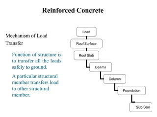
Reinforced cement concrete (RCC) is a composite material made of cement concrete reinforced with steel bars. Some key points:
- François Coignet built the first reinforced concrete structure, a four story house in Paris in 1853.
- RCC is used in the construction of columns, beams, footings, slabs, dams, water tanks, tunnels, bridges, walls and towers due to its high strength and durability.
- The steel reinforcement provides tensile strength, while the concrete primarily resists compressive forces and protects the steel from corrosion. Together they form a very strong, stable structural material.
Strength of concrete (for civil engineering) laxman singh
i have made all the slide for civil engineering and poly diploma civil.
these are 100% correct but in case of some error comment down or contact me on (laxmans227@gmail.com)
follow me for all updates
if u have any doubt fell free to ask on comment section
i upload new slides every sunday,
so keep calm and follow me(now).
software - power point presentation 2015
This Presentation about Brick Masonry with a Beautiful Slides. This presentation covers - Brick Masonry Definition, Type of Bricks, General Principals, Bonds of Bricks, Other Bonds, Junction in Walls, Bonds in Pires, Retraining Wall, Design of Retraining Wall, Strength of Brick Masonry, Reinforced Brickwork. Hope You Enjoy!
▶️ YouTube: https://www.youtube.com/c/JoynulAbadinRasel
☕ Buy me a Coffee: https://www.buymeacoffee.com/JoynulAbadinR
Concrete Construction: Batching of mixes; casting process, compaction and curing;
requirement of mix design and casting of test cubes – removing cubes from moulds and
curing for strength tests; bar-bending equipments and preparation of reinforcement for
R C C works
Description of concrete,wet and set concrete,binding materials,uses,different classifications according to binding materials,according to uses,according to design,according to purpose,and its respective uses.
The process of selecting suitable ingredients of concrete and determining their relative amounts with the objective of producing a concrete of the required, strength, durability, and workability as economically as possible, is termed the concrete mix design.
Reinforced Concrete (RC) design is the process of planning and specifying the construction of structures or components using reinforced concrete. Reinforced concrete is a composite material made up of concrete (a mixture of cement, water, and aggregates) and reinforcing steel bars or mesh, which enhances its strength and durability. RCC is commonly used in the construction of buildings, bridges, dams, highways, and various other infrastructure projects due to its versatility and strength.
It's important to note that RCC design can be quite complex and should be carried out by experienced structural engineers who have a deep understanding of the principles, codes, and standards related to reinforced concrete design. Additionally, local building authorities and regulations must be followed to ensure the safety and compliance of the structure.
Here are the key steps involved in RCC design:
Structural Analysis: The first step in RCC design is to analyze the structural requirements of the project. This involves determining the loads that the structure will need to support, such as dead loads (permanent loads like the weight of the structure itself) and live loads (variable loads like people, furniture, and equipment). Structural analysis helps in understanding the internal forces and moments acting on the structure.
Material Properties: Understanding the properties of the materials used in RCC is crucial. This includes knowledge of concrete mix design (proportions of cement, water, aggregates, and admixtures), as well as the properties of reinforcing steel (yield strength, tensile strength, etc.).
Design Codes and Standards: RCC design must adhere to local building codes and standards, which dictate safety and design criteria. These standards may vary by region or country, so it's important to consult the relevant codes for your project.
Structural Design: The structural design phase involves selecting appropriate dimensions for the structural elements (beams, columns, slabs, etc.) to withstand the anticipated loads. This involves calculations and considerations for factors like safety, serviceability, and economy.
Reinforcement Design: Once the structural elements are sized, the design of the reinforcement (rebar or mesh) is carried out. This includes determining the quantity, size, spacing, and placement of reinforcement to ensure the concrete can handle the expected tensile forces.
Detailing: Detailed drawings and specifications are created, specifying all the design details, including reinforcement layouts, concrete cover, joint locations, and more. Proper detailing is essential for construction contractors to follow the design accurately.
After construction, proper maintenance is essential to ensure the longevity and safety of the structure. This includes routine inspections, repairs, and protection against environmental factors like corrosion.
Quality control measures, such as testing concrete and inspecting reinforcement
Prepared by madam rafia firdous. She is a lecturer and instructor in subject of Plain and Reinforcement concrete at University of South Asia LAHORE,PAKISTAN.
This presentation is about RCC. one can find most of the information about RCC with architecture in mind. Structure Design - 2 Semester 2 B. Arch Notes
Definition Where this system can be used
Features of the Grid Slab
Decorative grid slabs in historical structures
Types of Grid Slab
Comparison: Long Span Structures
Construction
Technique
Formwork Required
Reinforcements Details
Modification in Grid Slab for Utility
Services Provided in Grid Slab
Benefits
Iconic Landmarks using Grid Slabs
Overview of the fundamental roles in Hydropower generation and the components involved in wider Electrical Engineering.
This paper presents the design and construction of hydroelectric dams from the hydrologist’s survey of the valley before construction, all aspects and involved disciplines, fluid dynamics, structural engineering, generation and mains frequency regulation to the very transmission of power through the network in the United Kingdom.
Author: Robbie Edward Sayers
Collaborators and co editors: Charlie Sims and Connor Healey.
(C) 2024 Robbie E. Sayers
Explore the innovative world of trenchless pipe repair with our comprehensive guide, "The Benefits and Techniques of Trenchless Pipe Repair." This document delves into the modern methods of repairing underground pipes without the need for extensive excavation, highlighting the numerous advantages and the latest techniques used in the industry.
Learn about the cost savings, reduced environmental impact, and minimal disruption associated with trenchless technology. Discover detailed explanations of popular techniques such as pipe bursting, cured-in-place pipe (CIPP) lining, and directional drilling. Understand how these methods can be applied to various types of infrastructure, from residential plumbing to large-scale municipal systems.
Ideal for homeowners, contractors, engineers, and anyone interested in modern plumbing solutions, this guide provides valuable insights into why trenchless pipe repair is becoming the preferred choice for pipe rehabilitation. Stay informed about the latest advancements and best practices in the field.
Hybrid optimization of pumped hydro system and solar- Engr. Abdul-Azeez.pdffxintegritypublishin
Advancements in technology unveil a myriad of electrical and electronic breakthroughs geared towards efficiently harnessing limited resources to meet human energy demands. The optimization of hybrid solar PV panels and pumped hydro energy supply systems plays a pivotal role in utilizing natural resources effectively. This initiative not only benefits humanity but also fosters environmental sustainability. The study investigated the design optimization of these hybrid systems, focusing on understanding solar radiation patterns, identifying geographical influences on solar radiation, formulating a mathematical model for system optimization, and determining the optimal configuration of PV panels and pumped hydro storage. Through a comparative analysis approach and eight weeks of data collection, the study addressed key research questions related to solar radiation patterns and optimal system design. The findings highlighted regions with heightened solar radiation levels, showcasing substantial potential for power generation and emphasizing the system's efficiency. Optimizing system design significantly boosted power generation, promoted renewable energy utilization, and enhanced energy storage capacity. The study underscored the benefits of optimizing hybrid solar PV panels and pumped hydro energy supply systems for sustainable energy usage. Optimizing the design of solar PV panels and pumped hydro energy supply systems as examined across diverse climatic conditions in a developing country, not only enhances power generation but also improves the integration of renewable energy sources and boosts energy storage capacities, particularly beneficial for less economically prosperous regions. Additionally, the study provides valuable insights for advancing energy research in economically viable areas. Recommendations included conducting site-specific assessments, utilizing advanced modeling tools, implementing regular maintenance protocols, and enhancing communication among system components.
Sachpazis:Terzaghi Bearing Capacity Estimation in simple terms with Calculati...Dr.Costas Sachpazis
Terzaghi's soil bearing capacity theory, developed by Karl Terzaghi, is a fundamental principle in geotechnical engineering used to determine the bearing capacity of shallow foundations. This theory provides a method to calculate the ultimate bearing capacity of soil, which is the maximum load per unit area that the soil can support without undergoing shear failure. The Calculation HTML Code included.
Welcome to WIPAC Monthly the magazine brought to you by the LinkedIn Group Water Industry Process Automation & Control.
In this month's edition, along with this month's industry news to celebrate the 13 years since the group was created we have articles including
A case study of the used of Advanced Process Control at the Wastewater Treatment works at Lleida in Spain
A look back on an article on smart wastewater networks in order to see how the industry has measured up in the interim around the adoption of Digital Transformation in the Water Industry.
Hierarchical Digital Twin of a Naval Power SystemKerry Sado
A hierarchical digital twin of a Naval DC power system has been developed and experimentally verified. Similar to other state-of-the-art digital twins, this technology creates a digital replica of the physical system executed in real-time or faster, which can modify hardware controls. However, its advantage stems from distributing computational efforts by utilizing a hierarchical structure composed of lower-level digital twin blocks and a higher-level system digital twin. Each digital twin block is associated with a physical subsystem of the hardware and communicates with a singular system digital twin, which creates a system-level response. By extracting information from each level of the hierarchy, power system controls of the hardware were reconfigured autonomously. This hierarchical digital twin development offers several advantages over other digital twins, particularly in the field of naval power systems. The hierarchical structure allows for greater computational efficiency and scalability while the ability to autonomously reconfigure hardware controls offers increased flexibility and responsiveness. The hierarchical decomposition and models utilized were well aligned with the physical twin, as indicated by the maximum deviations between the developed digital twin hierarchy and the hardware.
Immunizing Image Classifiers Against Localized Adversary Attacksgerogepatton
This paper addresses the vulnerability of deep learning models, particularly convolutional neural networks
(CNN)s, to adversarial attacks and presents a proactive training technique designed to counter them. We
introduce a novel volumization algorithm, which transforms 2D images into 3D volumetric representations.
When combined with 3D convolution and deep curriculum learning optimization (CLO), itsignificantly improves
the immunity of models against localized universal attacks by up to 40%. We evaluate our proposed approach
using contemporary CNN architectures and the modified Canadian Institute for Advanced Research (CIFAR-10
and CIFAR-100) and ImageNet Large Scale Visual Recognition Challenge (ILSVRC12) datasets, showcasing
accuracy improvements over previous techniques. The results indicate that the combination of the volumetric
input and curriculum learning holds significant promise for mitigating adversarial attacks without necessitating
adversary training.
2. Brief History
• François Coignet was a French industrialist of the
nineteenth century, a pioneer in the development of structural,
prefabricated and reinforced concrete.
• In 1853 Coignet built the first iron reinforced concrete structure, a four story
house inParis.
• Ernest L. Ransome, was an innovator of the reinforced concrete techniques in
the end of the 19thcentury
3. Uses of RCC
• It is used in the construction of Columns, Beams, Footings, Slabs etc.
• It is used in storage structures like Dams, Water Tanks, Tunnels etc.
• It is used to build heavy structures like Bridges, Walls, Towers, Under water
structures.
• It is used in tall structures and skyscrapers.
4. Why it is essential?
• High relative strength
• High toleration of tensile strain
• Good bond to the concrete, irrespective of pH, moisture, and
similar factors
• Thermal compatibility, not causing unacceptable stresses in response
to changingtemperatures.
• Durability in the concrete environment, irrespective of corrosion or sustained
stress forexample.
5. Merits of Reinforced Concrete
• Good Binding Between Steel and Concrete
there is a very good development of bond between steel and concrete.
• Stable Structure
Concrete is strong in compression but week in tension and steel as strong in
tension so their combination give a strong stable structure.
• Less Chances of Buckling
Concrete members are not slim like steel members so chances of
buckling are much less.
• Aesthetics
concrete structures are aesthetically good and cladding is not required
• Lesser Chances of Rusting
steel reinforcement is enclosed in concrete so chances of rusting are
reduced.
6. Short Reinforced Concrete Compression Members
Short - slenderness does not need to be considered–column will
not buckle
Only axial load
Cross-sectional
Areas:
As =Area ofsteel
Ac =Area of
concrete Ag =
Totalarea
Fs =stress in
steel
Fc =stress in
concrete
From Equilibrium:
P =Acfc +Asfs
L
P
If bond is maintained εs = εc
7. Reinforced Concrete
Load
Roof Surface
Roof Slab
Beams
Column
Foundation
Sub Soil
Mechanism of Load
Transfer
Function of structure is
to transfer all the loads
safely to ground.
A particular structural
member transfers load
to other structural
member.
8. Design Loads
Dead Load
“The loads which do not change their magnitude and
position w.r.t. time within the life of structure”
Dead load mainly consist of superimposed loads and self
load of structure.
Self Load
It is the load of structural member due to its own weight.
Superimposed Load
It is the load supported by a structural member. For
instance self weight of column is self load and load of beam and
slab over it is superimposed load.
9. Design Loads (contd…)
Live Load
“Live loads consist chiefly of occupancy loads in buildings
and traffic loads on bridges”
They may be either fully or partially in place or not present at all, and
may also change in location.
Their magnitude and distribution at any given time are uncertain, and even
their maximum intensities throughout the life time of the structure are not
known with precision.
The minimum live loads for which the floor and roof of a building should be
designed are usually specified in the building codes that governs at the site
construction.
10. Objectives of Designer
There are two main objectives
1. Safety
2. Economy
Safety
The structure should be safe enough to carry all the applied
throughout the life.
Economy
Structures should be economical. Lighter structures are more
economical.
Economy α1/self weight (More valid for Steel Structures)
In concrete Structures overall cost of construction decides the
economy, not just the self weight.
11. Load Combinations
To combine various loads in such a way to get a critical situation.
Load Factor = Factor by which a load is to be increased x probability of
occurrence
1. 1.2D + 1.6L
2. 1.4D
3. 1.2D + 1.6L + 0.5Lr
4. 1.2D + 1.6Lr + (1.0L or 0.8W)
Where
D = Dead load
L = Live load on intermediate floors
Lr = Live load on roof W
= Wind Load
12. Shrinkage
“Shrinkage is reduction in volume of concrete due to loss of water”
Coefficient of shrinkage varies with time. Coefficient of shortening is:
0.00025 at 28 days
0.00035 at 3 months
0.0005 at 12 months
Shrinkage = Shrinkage coefficient x Length
Excessive shrinkage can be avoided by proper curing during first 28
days because half of the total shrinkage takes place during this period
13. Creep
“creep is the slow deformation
of material over considerable
lengths of time at constant
stress or load”
Creep deformations for a given
concrete are practically
proportional to the magnitude of the
applied stress; at any given stress,
high strength concrete show less
creep than lower strength concrete.
Compressive
strength
Specific
Creep
(MPa) 10-6 perMPa
20 145
30 116
40 80
55 58
14. Plain & Reinforced Concrete
Creep (contd…)
How to calculate shortenings due to creep? Consider a column of 3m
which is under sustained load for several years.
Compressive strength, fc’ = 30 MPa
Sustained stress due to load = 10 MPa
Specific creep for 28 MPa fc’ = 116 x 10-6 per MPa Creep
Strain = 10 x 116 x 10-6 = 116 x 10-5
Shortening due to creep = 3000 x 116 x 10-5
= 3.48 mm
15. Strength measurement
Specified Compressive Strength Concrete, fc’
“28 days cylinder strength of concrete”
The cylinder has 150mm dia and 300mm length.
According to ASTM standards at least two cylinders should be tested
and their average is to be taken.
ACI 5.1.1: for concrete designed and constructed in accordance with ACI
code, fc’ shall not be less than 17 Mpa (2500 psi)
19. When the earthquake forces exceed the design parameters, the alternating forces
of the earthquake first break the concrete on one side of the column and
subsequently on the other side.
21. Building A :- has thick and stiff floors and
slender supportingcolumns.
During a earthquake, the whole building will pancake. the bottom columns
receive the largest forces and bend; wallscrack
Building B :- has a ductile floordesign.
During Earthquake, Floors will be waving and cracking, but the building
would notcollapse.
24. How to avoid corrosion?
⚫ Careful detailing to protect from water
⚫ Use stainless steel
⚫ Protect steel with galvanizing (zinc coating) or other
protective coating
25. Corrosion of Steel
Every 90 seconds, across the world, one ton of steel turns
to rust; of every two tons of steel made, one is to replace
rust.
26. • Most concrete used for construction is a combination of
concrete and reinforcement that is called reinforced
concrete.
• Steel is the most common material used as reinforcement, but
other materials such as fiber-reinforced polymer (FRP) are also
used
Reinforcement in aconcrete column
27. REINFORCEMENT USED IN RCC BUILDING
Fiber reinforcement:
Fiber-reinforced concrete (FRC) is concrete with the addition of discrete
reinforcing fibers made of steel, glass, synthetic(nylon, polyester, and
polypropylene), and natural fiber materials.
Synthetic fibers can be delivered to the mixing system in preweighed, degradable
bags that break down during the mixing cycle. Steel fibers are introduced to the
rotating mixer via conveyor belt, either at the same time as the coarse aggregate or
on their own after all the conventional ingredients have been added.
1. The major applications of FRC are slab-on-grade construction, precast concrete, and
shotcrete.
2. Some examples of slab-on-grade construction are airport runways, residential,
commercial, and industrial floor slabs, and hydraulic structures
3. Fiber- reinforced shotcrete is used for rock slope stabilization, tunnel liners,
hydraulic structures, and maintenance of existing concrete.
4. FRC is also used in repair applications, such as repair of bridge decks, piers, and
parapets.
28. Steel reinforcement:-Steel reinforcement is available in the form of plain steel
bars, deformed steel bars, cold-drawn wire, welded wire fabric, and deformed
welded wire fabric.
Deformed steel bars:—Deformed bars are round steelbars with lugs, or
deformations, rolled into the surface of the bar during manufacturing
Threaded steel bars:—Threaded steel bars are made by several
manufacturers in different grades They are used as an alternative to lapping
standard deformed bars when long bar lengths arerequired
Welded wire fabric:—Welded wire fabric reinforcement also known as welded
wire reinforcement is a square or rectangular mesh ofwires.
Typicaldeformed reinforcing bar
Welded wirereinforcement sheets
29. TYPES OF CONCRETE
1.Prestressed concrete:
Prestressed concrete is structural concrete in which internal stresses have
been introduced to reduce potential tensile stresses in the concrete
resulting from loads.
Applications
a. Toresist internal pressures in circular structures like tank,pipe
b. To limit cracking in bridge decks and slabs-on-grade.
c. To improve capacity of columns and piles.
d. To reduce long-term deflections.
2.Plain concrete:
Plain concrete is structural concrete withoutreinforcement
It is sometimes used in slabs-on grade ,pavement, basementwalls,
small foundations, and curb-and-gutter.
30. 3.Pretensioned concrete:
Pretensioning is usually performed in a factory (or precasting yard). The
tendons are held in place and tensioned against the ends of the casting
bed before the concrete is placed.
Advantages of pretensioned concrete are that it
tendons are bonded to the concrete over theirentire length.
4.Post-tensioned concrete:
Post-tensioning is usually performed at the job site. Post- tensioning tendons
are usually internal but can be external.
Some of the advantages of post-tensioning are that it does not require the
large temporary anchorages required for pretensioning,
It allows for larger members than are possible in aprecasting plant.
31. Plain & Reinforced Concrete
Reinforced Cement Concrete (RCC) contd..
Mix Proportion
Cement : Sand : Crush
1 : 1.5 : 3
1 : 2 : 4
Water Cement Ratio (W/C)
1 : 4 : 8
W/C = 0.5 – 0.6
For a mix proportion of 1:2:4 and W/C = 0.5, if cement is 50 kg
Batching By Weight
Sand
Crush
Water
= 2 x 50 = 100 Kg
= 4 x 50 = 200 Kg
= 50 x 0.5 = 25 Kg
33. Slabs
It is better to provide a max spacing of 200mm(8”) for main bars and
250mm(10”)in order to control the crack width and spacing.
A min. of 0.24% shall be used for the roof slabs since it is subjected to higher
temperature. Variations than the floor slabs. This is required to take care of
temp. differences.
It is advisable to not to use 6mm bars as main bars as this size available in
the local market is of inferior not only with respect to size but also the
quality since like TATAand SAILare not producing this size of bar.
34. Beams
A min. of 0.2% is to be provided for the compression bars in order to take care of
thedeflection.
The stirrups shall be minimum size of 8mm in the case of lateral load resistance .
The hooks shall be bent to 135degree.
36. Foundation
Minimum size of foundation for a single storey of G+1building, where
soil safe bearing capacity is 30 tonnes per square meter, and the oncoming
load on the column does not exceed 30tonnes.
Reinforcing bar details
37. Arrangement of reinforcement in various
structural members :
R.C.C. is used as a structural element, thecommon structural elements in
a buildingwhere
R.C.C. is used are:
(a) Footings (b) Columns
(c) Beams and lintels (d) roofs and slabs.
38. 1) Footings :
• In rectangular footing the reinforcement parallel to the long direction shall be
distributed uniformly across the width of the footing.
• In short direction, since the support provided to the Footing by the column is
concentrated near the middle, the moment per unit length is largest i.e., the
curvature of the footing is sharpest immediately under the column and
decreases in the long direction with the increasing distance from the column.
• For this reason larger steel area is needed in the central portion and is
determined in accordance with the equation given below.
39. 2) Columns :
The main reinforcement in columns in longitudinal , parallel to the direction
to the direction of the load and consists of bars arranged in square,
rectangular or spherical shape.
Main steel is provided to resist the compression load along with the
concrete.
The bar shall not be less than 12mmin diameter
Nominal max. Size of coarse aggregte is 5mm.
The no of bars in columns are varies from 10,12,14,16 with varyingdiameter.
40. 3) Beams :
Generally a beam consists of following types of
reinforcements :
Longitudinal reinforcement .
Shear reinforcements.
Side face reinforcement in the web of the beam isprovided
when the depth of the web in a beam exceeds 750mm.
Arrangements of bars in a beam should confirm to the requirements of
clause given in 8.1and 8.2of SP34.Bars of size 6,8,10,12,16,20,25,32,50 mm are
available in market.
41. Thickness of the slab is decided based on span to depth ratio . Min
reinforcement is 0.12% for HYSD bars and 0.15% for mild steel bars. The
diameter of bar generally used in slabs are: 6 mm, 8 mm, 10mm, 12mm and 16
mm.
The maximum diameter of bar used in slab should not exceed 1/8 of the total
thickness of slab. Maximum spacing of main bar is restricted to 3 times
effective depth . For distribution bars the maximum spacing is specified as 5
times the effective depth .
4) Slabs :
42. Minimum clear cover to reinforcements in slab depends on the durability
criteria . Generally 15 mm to 20 mm cover is provided for the main
reinforcements.
Torsion reinforcement shall be provided at any corner where the slab is
simply supported on both edges meeting at that corner.
It shall consist of top and bottom reinforcement, each with layer of bars
placed parallel to the sides of the slab and extending from the edges a
minimum distance of one fifth of the shorterspan.
43. Thank you
Mr. VIKAS MEHTA
School of Mechanical and civil engineering
Shoolini University
Village Bajhol, Solan (H.P)
vikasmehta@shooliniuniversity.com
+91 9459268898