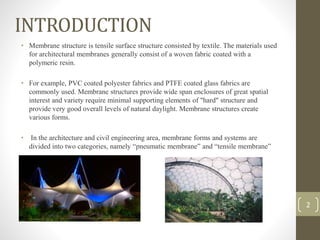
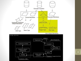
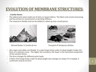
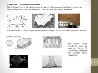
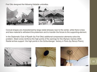
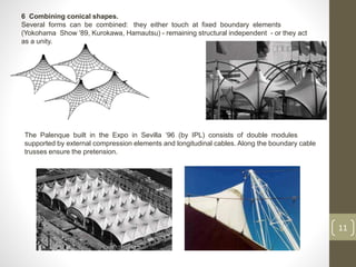
MEMBRANE
STRUCTURES
SUBMITTED BY-GROUP 5
Shreya Sable- BA13ARC041
Sachi Dongarwar- BA13ARC042
Saurabh Deotale- BA13ARC043
Shhrruti Jain- BA13ARC044
Shivangi Negi- BA13ARC045
SubhaMala- BA13ARC046
Swapnil Pudke- BA13ARC047
Vrinda Tapadia- BA13ARC048
Prasad Thanthratey- BA13ARC049
Pawan Tirpude- BA13ARC050
1
INTRODUCTION
• Membrane structure is tensile surface structure consisted by textile. The materials used
for architectural membranes generally consist of a woven fabric coated with a
polymeric resin.
• For example, PVC coated polyester fabrics and PTFE coated glass fabrics are
commonly used. Membrane structures provide wide span enclosures of great spatial
interest and variety require minimal supporting elements of "hard" structure and
provide very good overall levels of natural daylight. Membrane structures create
various forms.
• In the architecture and civil engineering area, membrane forms and systems are
divided into two categories, namely “pneumatic membrane” and “tensile membrane”
2
3
COMMON
MISCONCEPTIONS
4
FABRIC STRUCTURES CANNOT TAKE HEAVY WEATHER CONDITIONS  FALSE
FABRIC IS ELASTIC AND STRETCHES Fabric has a strong tensile strength and will creep
(stretch very slightly) only a few percent over 20 years of use.
ADVANTAGES
Unique designs
Lightweight and flexible
Environmentally sensitive
High strength weight ratio
DISADVANTAGES
Little to no rigidity
Loss of tension is dangerous for stability
Thermal values limit use
CLASSIFICATION
The structural use of membranes can be divided into
• pneumatic structures,
• tensile membrane structures, and
• cable domes.
In these three kinds of structure, membranes work together with cables, columns
and other construction members to find a form.
Membranes are also used as non-structural cladding, as at the Beijing National
Stadium where the spaces between the massive steel structural members are
infilled with PTFE coated glass fiber fabric and ETFE foil.
Materials
The common membranes used in membrane structures include:
 PVC coated polyester fabric
 Translucent Polyethylene fabric
 PVC coated glass fiber fabric
 PTFE coated glass fiber fabric; foils like
 ETFE foil
 PVC foil.
5
EVOLUTIONOFMEMBRANESTRUCTURES:
• 1 Earlier forms:
• The oldest tents were made out of skins or woven fabrics. The fabric only resists tensioning
and has almost no compression or bending stiffness.
• The material is flexible and can be folded or rolled up into a small parcel.
Nomad Shelter in Tundra & Iran Transport of Temporary Sheltes
• Also ropes and cables are flexible. If a rope hangs freely under its dead weight it takes the
form of a catenary curve. The higher the curvature, the lower is the horizontal component
of the reaction forces.
• The form changes for different point loads.
• A fabric that hangs freely under its dead weight also changes its shape if it is loaded, it
could even reverse its form.
•
6
2. Basic form : The Hypar or Saddle Shape:
The first basic form is the saddle shape. It has a double curvature: the hanging curve can
bear the downward load, the downward curve can bear the upward wind load.
7
The boundaries could be sloped arches (even forming a circle in plan view) or placed vertical.
The double curved
membrane could be
tensioned into a 3D
curved ring or between
two parallel circles
(polygons).
3 Combining saddle shapes.
Individual saddles could be placed in a grid, in this case they act as structurally independent
units.
8
In the next canopies small slightly curved saddles are jointed in a larger net: they
act all together.
4 Other possibilities with saddle shapes.
The next example is the roof above the architecture office of Willy Van Der Meeren
built in 1969. It was the first membrane roof, as far as I know, built in Belgium. Along its
boundary it has several high and low points.
The following structure built by Tensoforma has 4 high and 4 low boundary points. It is a
seasonal structure, the membrane is taken away during the winter.
9
5 Basic form 2: the conical shape.
Another basic form is the conical one with an
internal point out of the plane of the perimeter
support. Again this shape has a double curvature.
This time the horizontal rings bear the load from
inside to outside and radial lines bear the load
from outside to inside.
The high point can be supported by inner or outer
compression elements.
The conical form can be placed in the upright
position. In the umbrellas of the World Expo in
Lisbon ‘98 an inner frame takes the pretension.
Frei Otto designed the following foldable umbrellas.
10
Conical shapes are characterized by large radial stresses near to the center, while there is less
and less material to withstand the pretension and to transfer the forces to the supporting element.
In the Diplomatic Club of Ryadh (by Frei Otto) additional compression elements solve the
problem. Steel cones reinforce the high points of the awnings for the Olympic Games 2000.
Radial arches support the high points in the Schlumberger factory in Paris (by Renzo Piano).
6 Combining conical shapes.
Several forms can be combined: they either touch at fixed boundary elements
(Yokohama Show '89, Kurokawa, Hamautsu) - remaining structural independent - or they act
as a unity.
11
The Palenque built in the Expo in Sevilla ‘96 (by IPL) consists of double modules
supported by external compression elements and longitudinal cables. Along the boundary cable
trusses ensure the pretension.
7 Surfaces with conical regions.
Several high and low points could be used in the same roof.
12
The canopy built in the Markies building in Brussels is an example of conical forms jointed
together into one structure. Along its boundary it is fixed with cables to the second floor of the
building. Cables fixed at the sixth floor pull up the high points. The structure takes full
advantages of the heavy surrounding building.
The high points of the covering of the stand of Lord's cricket ground (by Hopkins) are
alternately supported by masts and cables. Transverse pretension is introduced by
compression elements connected to the masts.
8 Arch supported shapes.
The following basic unit is supported by an arch. The built roof is constructed for the
Olympic Games 2000 in Sydney.
13
Also the Diadema for the Expo in Sevilla ‘96 (by IPL) can be considered to be supported by an
arch. Due to the fact that this is a high structure, special wind tunnel tests have been performed
to be sure to dimension this structure properly.
9 Combining arch supported shapes.
The Zenith in Paris and in Montpellier (by Chaix, Morel) are covered by square modules each
one tensioned by a diagonal arch.
14
10 More possibilities for arch supported shapes.
Arches could be placed parallel.
The Fina Service Station in Wanlin was designed by Samyn & Partners.
15
The equilibrium calculations were performed with EASY. The
structure stands upon 6 concrete columns. They hold 3
planar arches in the transverse direction. Compression
elements transmit the compression from one end to the other.
The curvature for the upward wind (which could be high for an
open structure) is quite small and for that reason cable trusses
were added under the roof. They only act for upward wind.
11 Wave forms
Another type of structure is the wave form, based on a two-
dimensional system with a load bearing cable, a tensioning cable and
connecting cable elements. If the load bearing cables and tensioning
cables are placed in parallel planes a wave form is obtained.
For the structure used in the World
Expo in Brisbane ‘88 (by IPL) a similar
principle was arranged radially. Extra
cables pull the structure downward to
withstand the large wind loads on this
high construction.
16
12 Tensegrity.
The possibility to support structures by means of floating masts has already been
mentioned. Sculptures have been made which consists of bars and cable elements in such a
way that an endpoint of a bar only touches cable elements. They are called tensegrity
structures.
ADVANTAGESOFMEMBRANESTRUCTURE
Aesthetics/Design
• Tensile membrane structures have a unique visual character and give
designers, architects and engineers the ability to experiment with form and
create exciting new solutions to conventional design problems.
Code Compliance
• PTFE fiberglass membrane systems properly meet the requirements for the
model codes for fire performance. Because of PTFE’s superior fire
performance, it can be used in all types of construction providing they meet
with height and clearance requirements.
Daylighting
• During scientific tests of its solar properties, it was discovered that PTFE
fiberglass membranes reflect approximately 72-75 percent of the sun’s
radiated solar energy while allowing in approximately 8 to 20 percent of
natural daylight to permeate the membrane depending on the strength and
thickness of the material. 17
Durability
• The durability of tensile membrane structures and their maintenance
requirements is the result of the unique combination of design, materials,
construction and environment. There are several different membranes in
the market place today that demonstrate various performance qualities.
Energy Use & Lighting
• Tensile membrane structures have high sun reflectivity and low absorption
of sunlight. This greatly reduces the solar energy and heat gain that enters
the structure, thus resulting in less energy used within a building. The
membrane allows for natural daylight to enter into the interior making it a
comfortable space while reducing electrical energy costs as there is
significantly less use of artificial lighting during the day time. These
beneficial characteristics have made fabric membrane readily applicable for
use in temperate or hot climates with high solar radiation.
18
COMPONENTS
Connection to concrete foundation pillar
19
BALE RING / MEMBRANE PLATE
Provide a link between the membrane and structural elements..
Bale rings are used at the top of conical shapes.
Membrane plates accept centenary cables and pin connection hardware.
MEMBRANE
Forms the enclosure of the structure. Connections can be
glued or heat welded.
20
Water drainage
via membrane
plates open
structure
TYPES OF FABRIC MEMBRANES
PVC
Less expensive
15 to 20 year life span
Easy to erect
SILICON GLASS
Higher tensile strength
Brittle, subject to damage from flexing
30+ year life span
TEFLON GLASS
Similar to silicon glass, less brittle.
21
SPECIALIZED HARDWARE
Centenary cables at a side connectionTripod head with centenary cables
Tensioner
Extruded section with membrane plate and
centenary cables

Case Study: Membrane Structures

  • 1.
    MEMBRANE STRUCTURES SUBMITTED BY-GROUP 5 ShreyaSable- BA13ARC041 Sachi Dongarwar- BA13ARC042 Saurabh Deotale- BA13ARC043 Shhrruti Jain- BA13ARC044 Shivangi Negi- BA13ARC045 SubhaMala- BA13ARC046 Swapnil Pudke- BA13ARC047 Vrinda Tapadia- BA13ARC048 Prasad Thanthratey- BA13ARC049 Pawan Tirpude- BA13ARC050 1
  • 2.
    INTRODUCTION • Membrane structureis tensile surface structure consisted by textile. The materials used for architectural membranes generally consist of a woven fabric coated with a polymeric resin. • For example, PVC coated polyester fabrics and PTFE coated glass fabrics are commonly used. Membrane structures provide wide span enclosures of great spatial interest and variety require minimal supporting elements of "hard" structure and provide very good overall levels of natural daylight. Membrane structures create various forms. • In the architecture and civil engineering area, membrane forms and systems are divided into two categories, namely “pneumatic membrane” and “tensile membrane” 2
  • 3.
  • 4.
    COMMON MISCONCEPTIONS 4 FABRIC STRUCTURES CANNOTTAKE HEAVY WEATHER CONDITIONS  FALSE FABRIC IS ELASTIC AND STRETCHES Fabric has a strong tensile strength and will creep (stretch very slightly) only a few percent over 20 years of use. ADVANTAGES Unique designs Lightweight and flexible Environmentally sensitive High strength weight ratio DISADVANTAGES Little to no rigidity Loss of tension is dangerous for stability Thermal values limit use
  • 5.
    CLASSIFICATION The structural useof membranes can be divided into • pneumatic structures, • tensile membrane structures, and • cable domes. In these three kinds of structure, membranes work together with cables, columns and other construction members to find a form. Membranes are also used as non-structural cladding, as at the Beijing National Stadium where the spaces between the massive steel structural members are infilled with PTFE coated glass fiber fabric and ETFE foil. Materials The common membranes used in membrane structures include:  PVC coated polyester fabric  Translucent Polyethylene fabric  PVC coated glass fiber fabric  PTFE coated glass fiber fabric; foils like  ETFE foil  PVC foil. 5
  • 6.
    EVOLUTIONOFMEMBRANESTRUCTURES: • 1 Earlierforms: • The oldest tents were made out of skins or woven fabrics. The fabric only resists tensioning and has almost no compression or bending stiffness. • The material is flexible and can be folded or rolled up into a small parcel. Nomad Shelter in Tundra & Iran Transport of Temporary Sheltes • Also ropes and cables are flexible. If a rope hangs freely under its dead weight it takes the form of a catenary curve. The higher the curvature, the lower is the horizontal component of the reaction forces. • The form changes for different point loads. • A fabric that hangs freely under its dead weight also changes its shape if it is loaded, it could even reverse its form. • 6
  • 7.
    2. Basic form: The Hypar or Saddle Shape: The first basic form is the saddle shape. It has a double curvature: the hanging curve can bear the downward load, the downward curve can bear the upward wind load. 7 The boundaries could be sloped arches (even forming a circle in plan view) or placed vertical. The double curved membrane could be tensioned into a 3D curved ring or between two parallel circles (polygons).
  • 8.
    3 Combining saddleshapes. Individual saddles could be placed in a grid, in this case they act as structurally independent units. 8 In the next canopies small slightly curved saddles are jointed in a larger net: they act all together. 4 Other possibilities with saddle shapes. The next example is the roof above the architecture office of Willy Van Der Meeren built in 1969. It was the first membrane roof, as far as I know, built in Belgium. Along its boundary it has several high and low points.
  • 9.
    The following structurebuilt by Tensoforma has 4 high and 4 low boundary points. It is a seasonal structure, the membrane is taken away during the winter. 9 5 Basic form 2: the conical shape. Another basic form is the conical one with an internal point out of the plane of the perimeter support. Again this shape has a double curvature. This time the horizontal rings bear the load from inside to outside and radial lines bear the load from outside to inside. The high point can be supported by inner or outer compression elements. The conical form can be placed in the upright position. In the umbrellas of the World Expo in Lisbon ‘98 an inner frame takes the pretension.
  • 10.
    Frei Otto designedthe following foldable umbrellas. 10 Conical shapes are characterized by large radial stresses near to the center, while there is less and less material to withstand the pretension and to transfer the forces to the supporting element. In the Diplomatic Club of Ryadh (by Frei Otto) additional compression elements solve the problem. Steel cones reinforce the high points of the awnings for the Olympic Games 2000. Radial arches support the high points in the Schlumberger factory in Paris (by Renzo Piano).
  • 11.
    6 Combining conicalshapes. Several forms can be combined: they either touch at fixed boundary elements (Yokohama Show '89, Kurokawa, Hamautsu) - remaining structural independent - or they act as a unity. 11 The Palenque built in the Expo in Sevilla ‘96 (by IPL) consists of double modules supported by external compression elements and longitudinal cables. Along the boundary cable trusses ensure the pretension.
  • 12.
    7 Surfaces withconical regions. Several high and low points could be used in the same roof. 12 The canopy built in the Markies building in Brussels is an example of conical forms jointed together into one structure. Along its boundary it is fixed with cables to the second floor of the building. Cables fixed at the sixth floor pull up the high points. The structure takes full advantages of the heavy surrounding building. The high points of the covering of the stand of Lord's cricket ground (by Hopkins) are alternately supported by masts and cables. Transverse pretension is introduced by compression elements connected to the masts.
  • 13.
    8 Arch supportedshapes. The following basic unit is supported by an arch. The built roof is constructed for the Olympic Games 2000 in Sydney. 13 Also the Diadema for the Expo in Sevilla ‘96 (by IPL) can be considered to be supported by an arch. Due to the fact that this is a high structure, special wind tunnel tests have been performed to be sure to dimension this structure properly.
  • 14.
    9 Combining archsupported shapes. The Zenith in Paris and in Montpellier (by Chaix, Morel) are covered by square modules each one tensioned by a diagonal arch. 14 10 More possibilities for arch supported shapes. Arches could be placed parallel. The Fina Service Station in Wanlin was designed by Samyn & Partners.
  • 15.
    15 The equilibrium calculationswere performed with EASY. The structure stands upon 6 concrete columns. They hold 3 planar arches in the transverse direction. Compression elements transmit the compression from one end to the other. The curvature for the upward wind (which could be high for an open structure) is quite small and for that reason cable trusses were added under the roof. They only act for upward wind. 11 Wave forms Another type of structure is the wave form, based on a two- dimensional system with a load bearing cable, a tensioning cable and connecting cable elements. If the load bearing cables and tensioning cables are placed in parallel planes a wave form is obtained. For the structure used in the World Expo in Brisbane ‘88 (by IPL) a similar principle was arranged radially. Extra cables pull the structure downward to withstand the large wind loads on this high construction.
  • 16.
    16 12 Tensegrity. The possibilityto support structures by means of floating masts has already been mentioned. Sculptures have been made which consists of bars and cable elements in such a way that an endpoint of a bar only touches cable elements. They are called tensegrity structures.
  • 17.
    ADVANTAGESOFMEMBRANESTRUCTURE Aesthetics/Design • Tensile membranestructures have a unique visual character and give designers, architects and engineers the ability to experiment with form and create exciting new solutions to conventional design problems. Code Compliance • PTFE fiberglass membrane systems properly meet the requirements for the model codes for fire performance. Because of PTFE’s superior fire performance, it can be used in all types of construction providing they meet with height and clearance requirements. Daylighting • During scientific tests of its solar properties, it was discovered that PTFE fiberglass membranes reflect approximately 72-75 percent of the sun’s radiated solar energy while allowing in approximately 8 to 20 percent of natural daylight to permeate the membrane depending on the strength and thickness of the material. 17
  • 18.
    Durability • The durabilityof tensile membrane structures and their maintenance requirements is the result of the unique combination of design, materials, construction and environment. There are several different membranes in the market place today that demonstrate various performance qualities. Energy Use & Lighting • Tensile membrane structures have high sun reflectivity and low absorption of sunlight. This greatly reduces the solar energy and heat gain that enters the structure, thus resulting in less energy used within a building. The membrane allows for natural daylight to enter into the interior making it a comfortable space while reducing electrical energy costs as there is significantly less use of artificial lighting during the day time. These beneficial characteristics have made fabric membrane readily applicable for use in temperate or hot climates with high solar radiation. 18
  • 19.
    COMPONENTS Connection to concretefoundation pillar 19 BALE RING / MEMBRANE PLATE Provide a link between the membrane and structural elements.. Bale rings are used at the top of conical shapes. Membrane plates accept centenary cables and pin connection hardware. MEMBRANE Forms the enclosure of the structure. Connections can be glued or heat welded.
  • 20.
    20 Water drainage via membrane platesopen structure TYPES OF FABRIC MEMBRANES PVC Less expensive 15 to 20 year life span Easy to erect SILICON GLASS Higher tensile strength Brittle, subject to damage from flexing 30+ year life span TEFLON GLASS Similar to silicon glass, less brittle.
  • 21.
    21 SPECIALIZED HARDWARE Centenary cablesat a side connectionTripod head with centenary cables Tensioner Extruded section with membrane plate and centenary cables