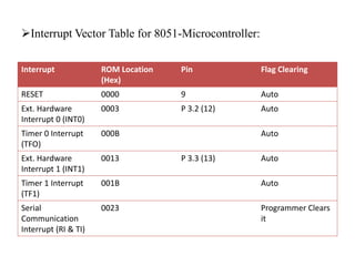
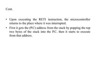
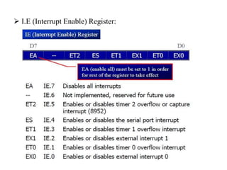
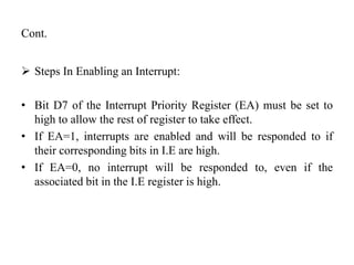
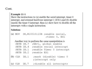
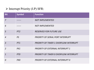
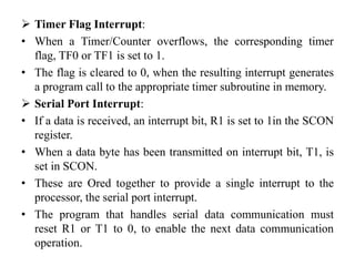
2. 8051-Microcontoller Interrupts
Interrupts Vs. Polling:
• A single microcontroller can serve several devices.
• There are two ways to do that: ‘Interrupt or Polling’
• In the ‘Interrupt’ method, whenever any device needs its
service, the device notifies the microcontroller by sending it an
interrupt signal.
• Upon receiving an interrupt signal, the microcontroller
interrupts whatever it is doing and serves the device.
• The program associated with the interrupt is called “Interrupt
Service Routine (ISR) or Interrupt Handler”.
3. Cont.
• In ‘Polling’ the microcontroller continuously monitors the
status of a given device, when the status condition is met, it
performs the service.
• After that, it moves on to monitor the next device until each
one is serviced.
• Although polling can monitor the status of several devices and
serve each of them as certain conditions are met, it is not an
efficient use of the microcontroller.
• The advantage of interrupt is that the microcontroller can serve
many devices (not all at the same time) each device can get the
attention of the microcontroller based on the priority assigned
to it.
4. Cont.
• The polling method cannot assign priority since it checks all
devices in a round-robin fashion.
• More importantly, in the interrupt method the microcontroller
can also ignore (mask) a device request for service, this is
again not possible with the polling method.
• The most important reason that the interrupt method is
preferable is that the polling method wastes much of the
microcontroller time by polling devices that do not need
service.
5. Interrupt Service Routine:
• For every interrupt, there must be an Interrupt Service Routine
(ISR) or Interrupt Handler.
• When an interrupt is invoked, the microcontroller runs the
ISR.
• For every interrupt, there is a fixed location in the memory that
holds the address of its ISR.
• The group of memory locations set aside to hold the addresses
of ISR’s is called the ‘Interrupt Vector Table’.
6. Interrupt Vector Table for 8051-Microcontroller:
Interrupt ROM Location
(Hex)
Pin Flag Clearing
RESET 0000 9 Auto
Ext. Hardware
Interrupt 0 (INT0)
0003 P 3.2 (12) Auto
Timer 0 Interrupt
(TFO)
000B Auto
Ext. Hardware
Interrupt 1 (INT1)
0013 P 3.3 (13) Auto
Timer 1 Interrupt
(TF1)
001B Auto
Serial
Communication
Interrupt (RI & TI)
0023 Programmer Clears
it
7. Steps In Executing an Interrupt:
• Upon activation of an interrupt, the microcontroller goes
through the following steps.
• It finishes the instruction it is executing and saves the address
of the next instruction (P.C) on the stack.
• It also saves the current status of all the interrupts internally.
• It jumps to a fixed location in memory called the interrupt
vector table that holds the address of the Interrupt Service
Routine.
• The microcontroller gets the address of the ISR from the
interrupt vector table and jumps to it.
• It starts to execute the interrupt service subroutine until it
reaches the last inst. Of the subroutine, which is RETI (Return
from Interrupt).
8. Cont.
• Upon executing the RETI instruction, the microcontroller
returns to the place where it was interrupted.
• First it gets the (P.C) address from the stack by popping the top
two bytes of the stack into the P.C. then it starts to execute
from that address.
9. Six Interrupts In 8051:
• In reality only five interrupts are available to the user in the
8051, but many manufacturers data sheet state that there are
six interrupts since they include RESET.
• RESET, when the reset pin is activated, the 8051 jumps to
address location 0000. this is power up-reset.
• Two interrupts are set aside for the timers: one for timer 0 and
one for timer 1, memory locations 000BH & 001BH in the
interrupt vector table belongs to Timer 0 & Timer 1.
• Two interrupts are set aside for hardware, external hardware
interrupt. Pin no. 12 and 13 in port 3are for the external
hardware interrupt INT0 & INT1. These external interrupts are
also referred to as EX1 & EX2, memory locations 0003H and
0013H are assigned to INT0 & INT1.
10. Cont.
• Serial communication has a single interrupt that belongs to
both receive and transmit. The interrupt vector table location
0023H belongs to this interrupt.
Enabling & Disabling An Interrupt:
• Upon reset, all interrupts are disabled (masked), meaning that
none will be responded to by the microcontroller if they are
activated.
• The interrupts must be enabled by software in order for the
microcontroller to respond to them.
• There is a register called IE (Interrupt Enable) that is
responsible for enabling (unmasking) and disabling (masking)
the interrupt. IE is a bit addressable register.
12. Cont.
Steps In Enabling an Interrupt:
• Bit D7 of the Interrupt Priority Register (EA) must be set to
high to allow the rest of register to take effect.
• If EA=1, interrupts are enabled and will be responded to if
their corresponding bits in I.E are high.
• If EA=0, no interrupt will be responded to, even if the
associated bit in the I.E register is high.
14. Interrupt Priority (I.P) SFR:
Bit Symbol Function
7 ------ NOT IMPLEMENTED
6 ------ NOT IMPLEMENTED
5 PT2 RESERVED FOR FUTURE USE
4 PS PRIORITY OF SERIAL PORT INTERRUPT
3 PT1 PRIORITY OF TIMER 1 OVERFLOW INTERRUPT
2 PX1 PRIORITY OF EXTERNAL INTERRUPT 1
1 PT0 PRIORITY OF TIMER 0 OVERFLOW INTERRUPT
0 PX0 PRIORITY OF EXTERNAL INTERRUPT 0
15. Timer Flag Interrupt:
• When a Timer/Counter overflows, the corresponding timer
flag, TF0 or TF1 is set to 1.
• The flag is cleared to 0, when the resulting interrupt generates
a program call to the appropriate timer subroutine in memory.
Serial Port Interrupt:
• If a data is received, an interrupt bit, R1 is set to 1in the SCON
register.
• When a data byte has been transmitted on interrupt bit, T1, is
set in SCON.
• These are Ored together to provide a single interrupt to the
processor, the serial port interrupt.
• The program that handles serial data communication must
reset R1 or T1 to 0, to enable the next data communication
operation.
16. Cont.
External Interrupts:
• Pins INT0 & INT1 are used by external circuitry.
• Inputs on these pins can set the interrupt flags IE0 & IE1 in the
TCON register to 1 by two different methods.
• The IEX flags may be set when the INTX pin signal reaches a
low level, or the flags may be set when a high-to-low
transition takes place on the INTX pin.
• Bits IT0 & IT1 in TCON, program the INTX pins for low-
level interrupt.
• When set to 0 and program the INTX pins for transition
interrupt when set to 1
17. Cont.
RESET:
• A reset can be considered to be the ultimate interrupt because
the program may not block the action of the voltage on the
RST pin.
• This type of interrupt is often called non-maskable, because no
combination of bits in any register can stop or mask the reset
action.
• Whenever a high level is applied to the RST pin, the 8051
enters a reset condition.
• After the RST pin is bought low, the internal registers will
have the different values.
• Internal RAM contents may change during reset.
• Register bank 0 is selected on reset as all bits in PSW are 0.
18. Interrupt Priority:
• Register IP bits determine if any interrupt is to have a high or
low priority.
• Bits set to 1 give the accompanying interrupt a high priority, a
0 assigns a low priority.
• Interrupts with a high priority can interrupt another interrupt
with a lower priority, the lower priority interrupt continues
after the higher is finished.
• If two interrupts with the same priority occurs at the same
time, then they have the following ranking:
1. IE0
2. TF0
3. IE1
4. TF1
5. Serial = R1 or T1
19. Thank-You
Learning outcomes of today’s lesson:
• Interrupt vs. Polling
• Interrupt Service Routine
• Interrupt Vector Table
• Steps in Executing an Interrupt
• 8051 Interrupts
• Enabling & Disabling an Interrupt
• Interrupt Enable (I.E) Register
• Interrupt Priority