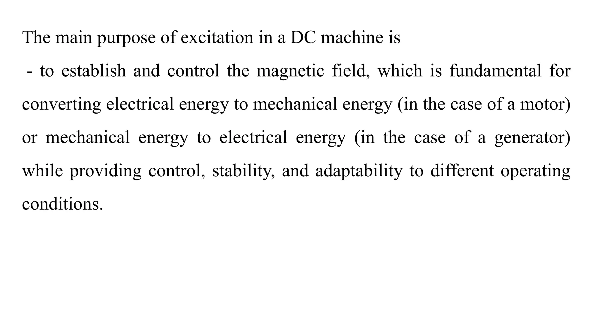
The document details the operation principles of DC machines, focusing on motoring and generation modes, the types of field excitations, and critical characteristics affecting voltage build-up and performance. It outlines equations governing armature circuits, types of excitation (separately and self-excited), and provides applications for different types of DC motors such as shunt, series, and compound motors. Additionally, it discusses the significance of back electromotive force (emf) and how machine functionality is influenced by armature current and field resistance.


![Internal Characteristics
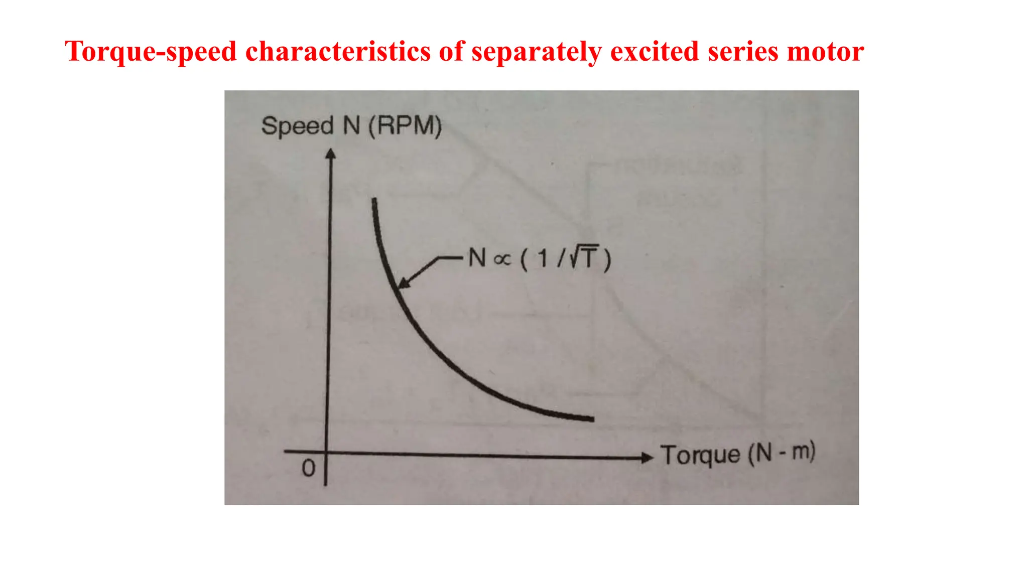
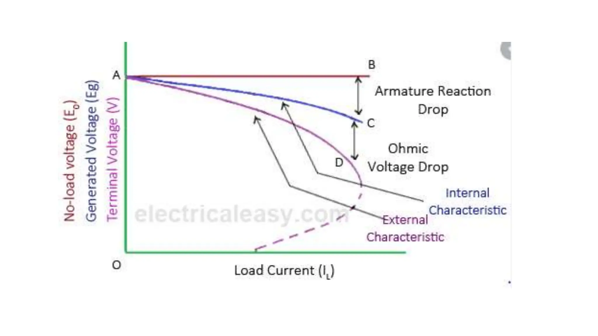
• The internal characteristics of a DC series motor is the graph plotted
between generated EMF (Eg) on-load and the armature current.
• Because of the effect of armature reaction, the magnetic flux on-load
will be less than the flux at no-load.
• Therefore, the generated EMF (E) under loaded condition will be less
than the EMF generated (E0) at no-load.
• As a result of this, the internal characteristics curve lies just below the
open circuit characteristics [See the curve (B)].](https://image.slidesharecdn.com/dcmachine-240506165359-9448b586/75/DC-MACHINE-Motoring-and-generation-Armature-circuit-equation-87-2048.jpg)
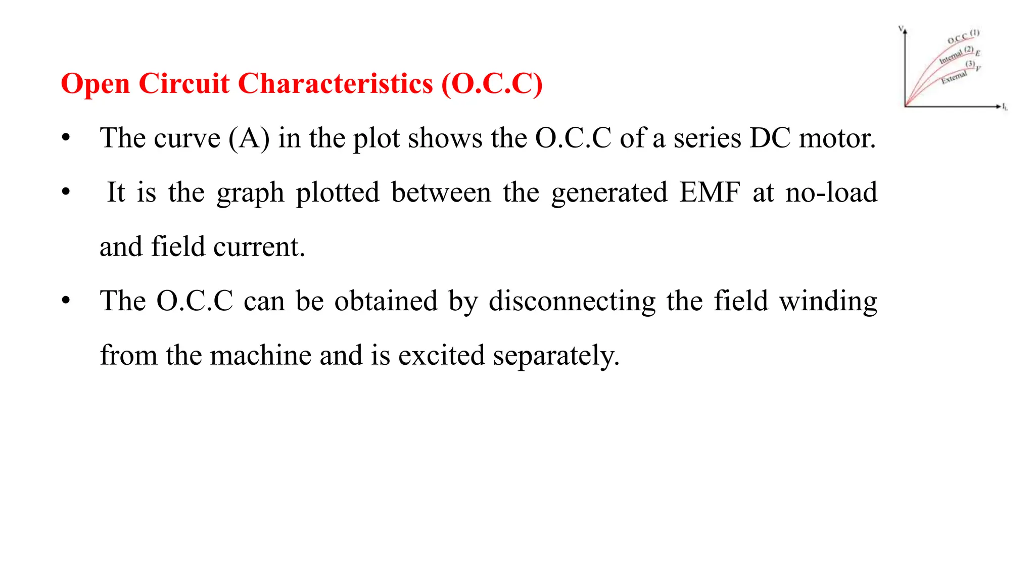
![External Characteristics or Load Characteristics
• The external characteristics or load characteristics is the plot
between the terminal voltage (V) and load current (IL}).
• Since, the terminal voltage is less than the generated voltage due
to armature and series field copper losses, which is given by,
V = E − Ia ( Ra + Rse )
• Therefore, the external characteristics curve will lie below the
internal characteristics curve by an equal amount to voltage drop
due to copper losses in the machine [see the curve (C)].](https://image.slidesharecdn.com/dcmachine-240506165359-9448b586/75/DC-MACHINE-Motoring-and-generation-Armature-circuit-equation-88-2048.jpg)