Downloaded 118 times


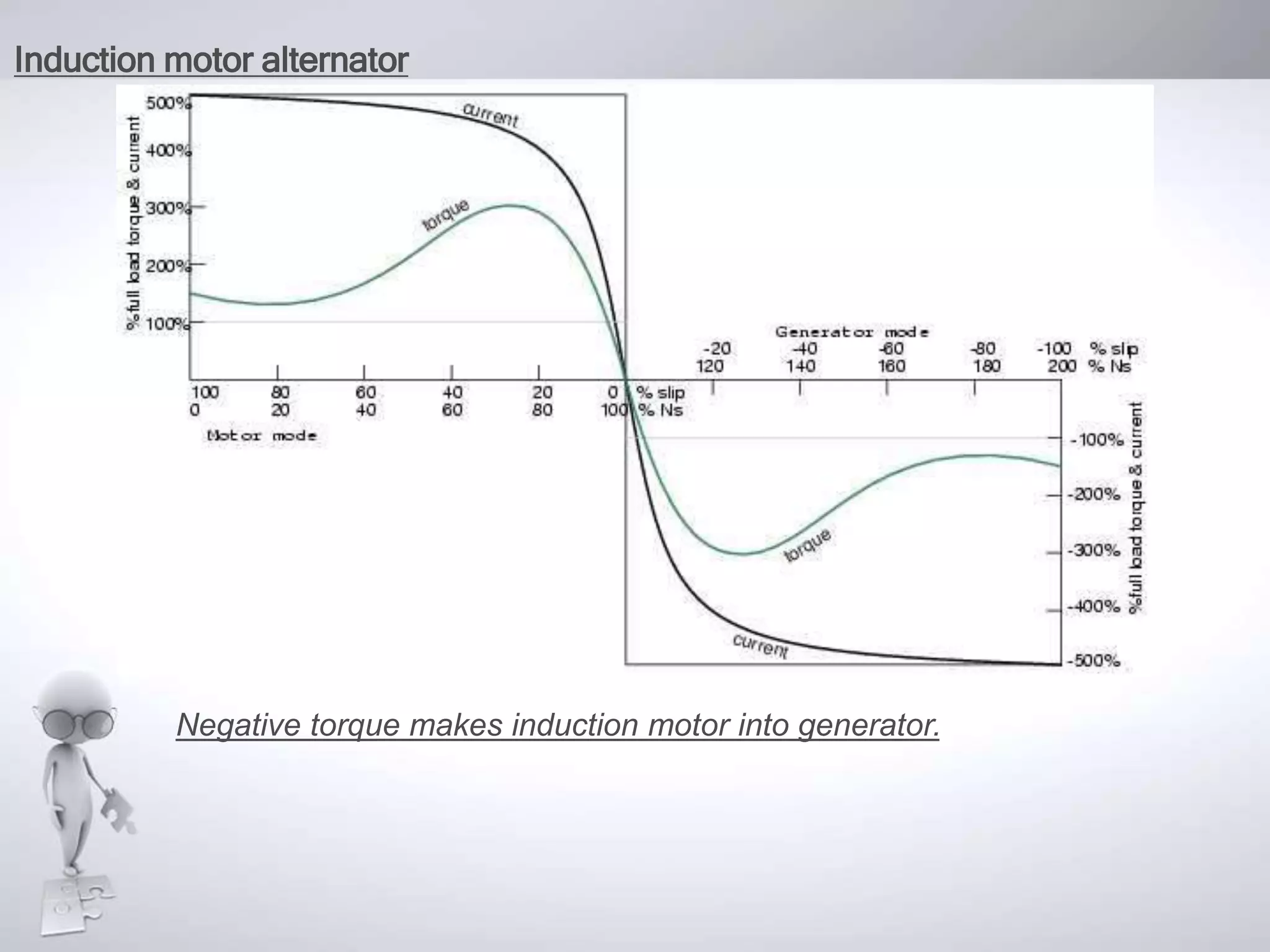
![• An induction motor may function as an alternator if it is driven by a torque
at greater than 100% of the synchronous speed. This corresponds to a
few % of “negative” slip, say -1% slip. This means that as we are rotating
the motor faster than the synchronous speed, the rotor is advancing 1%
faster than the stator rotating magnetic field. It normally lags by 1% in a
motor. Since the rotor is cutting the stator magnetic field in the opposite
direction (leading), the rotor induces a voltage into the stator feeding
electrical energy back into the power line.
• Such an induction generator must be excited by a “live” source of 50 or 60
Hz power. No power can be generated in the event of a power company
power failure. This type of alternator appears to be unsuited as a standby
power source. As an auxiliary power wind turbine generator, it has the
advantage of not requiring an automatic power failure disconnect switch to
protect repair crews. It is fail-safe.
• Small remote (from the power grid) installations may be make self-exciting
by placing capacitors in parallel with the stator phases. If the load is
removed residual magnetism may generate a small amount of current
flow. This current is allowed to flow by the capacitors without dissipating
power. As the generator is brought up to full speed, the current flow
increases to supply a magnetizing current to the stator. The load may be
applied at this point. Voltage regulation is poor. An induction motor may be
converted to a self-excited generator by the addition of capacitors.[6]](https://image.slidesharecdn.com/montiveros-150731074433-lva1-app6891/75/polyphase-induction-motor-25-2048.jpg)


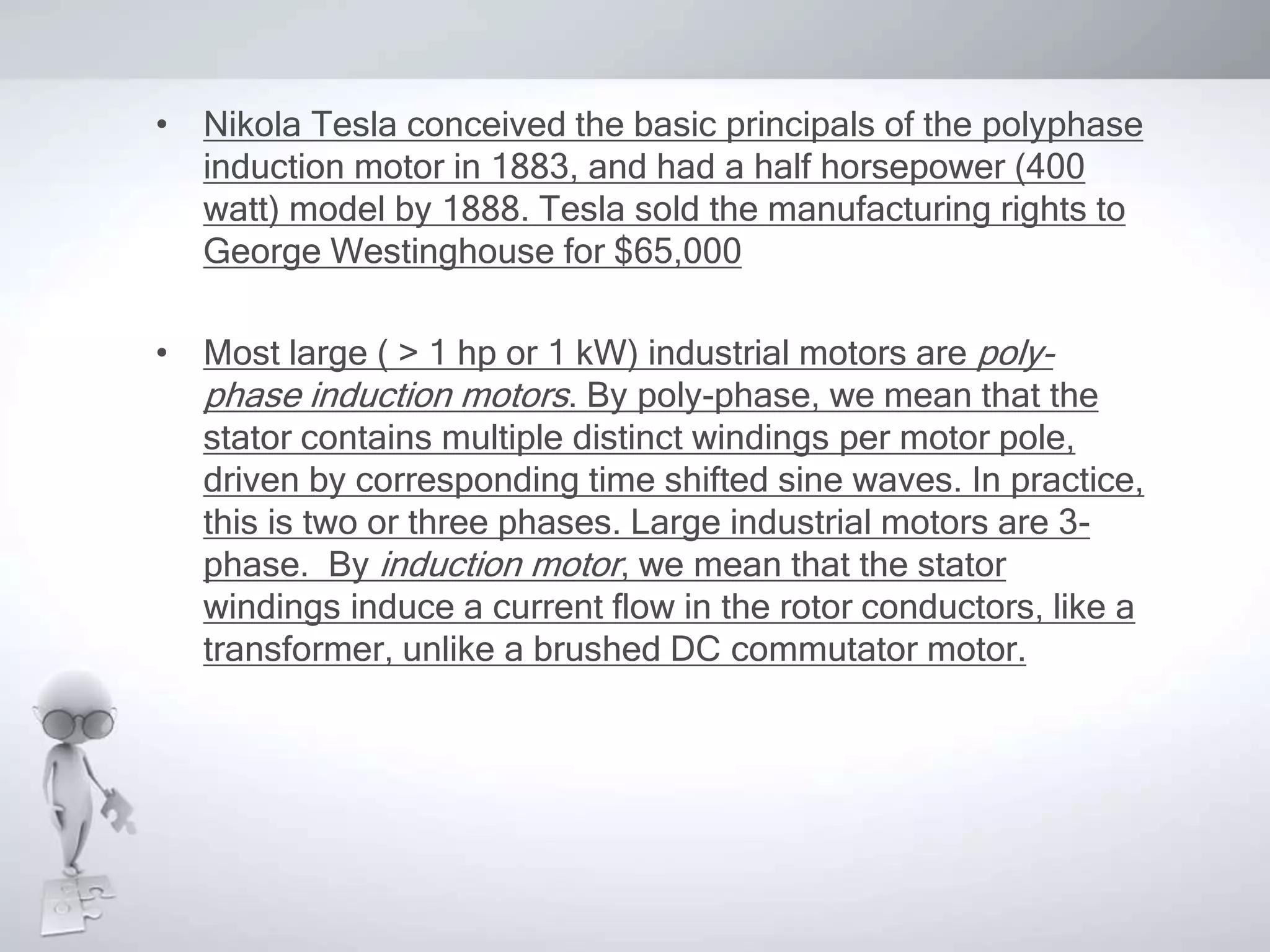
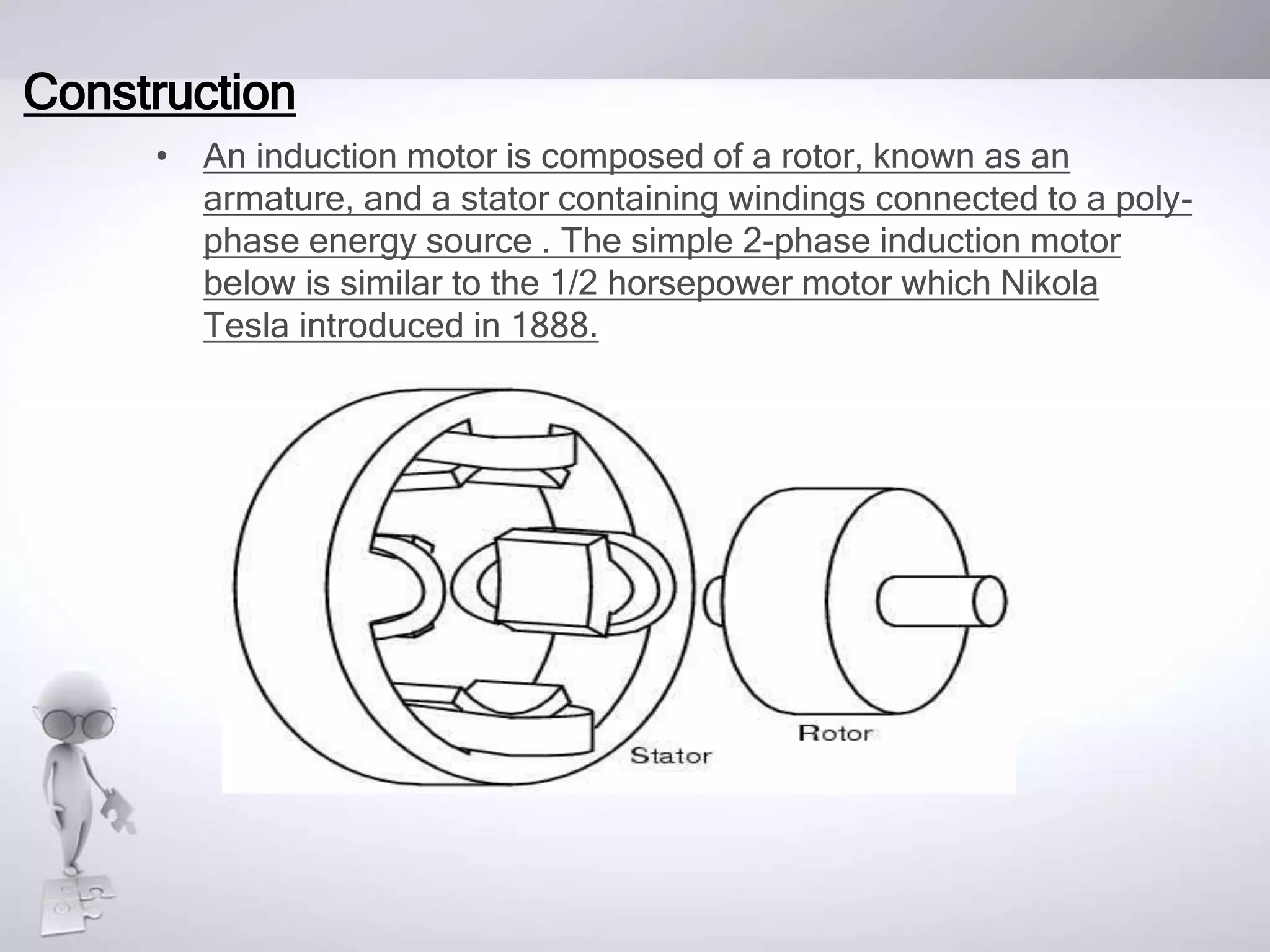
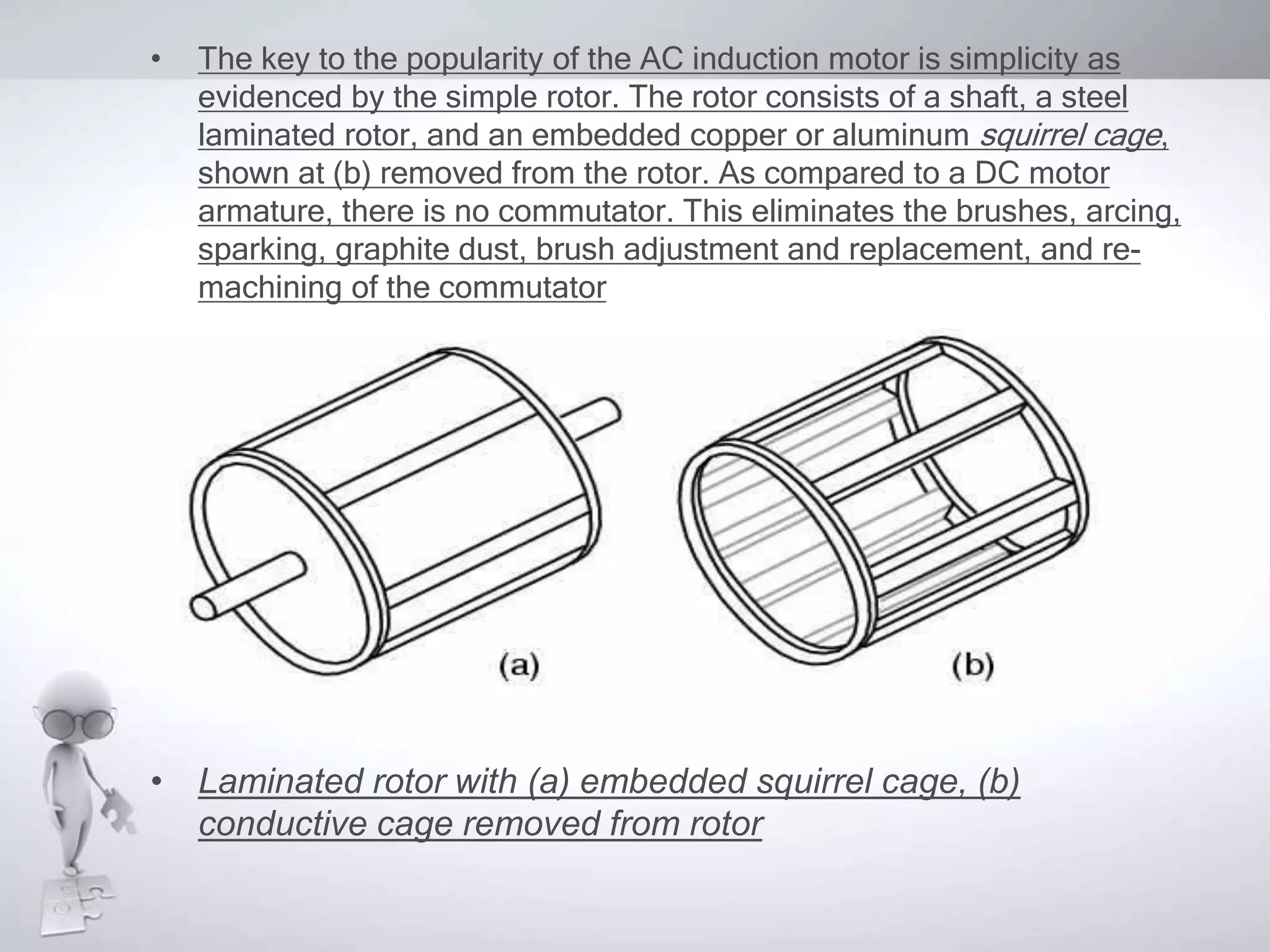
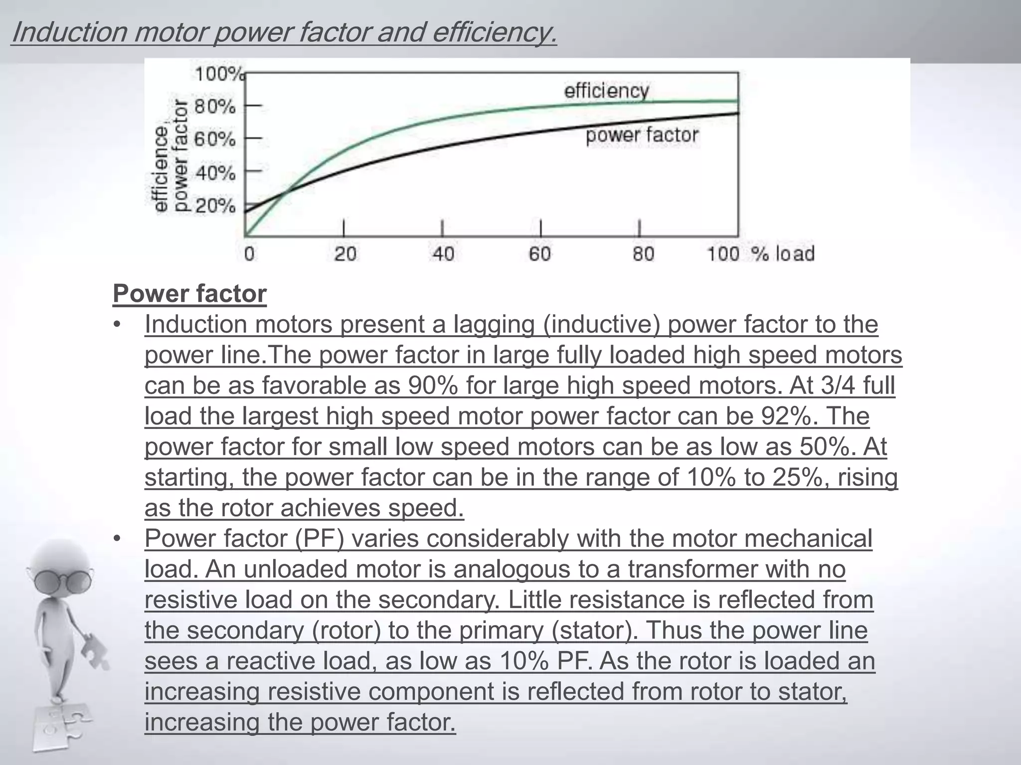
The document summarizes the key aspects of polyphase induction motors, including: 1) Nikola Tesla conceived the induction motor in 1883 and sold the rights to George Westinghouse. Most large industrial motors are polyphase induction motors with multiple stator windings driven by time-shifted sine waves, usually two or three phases. 2) An induction motor has a rotor and stator, with the stator windings connected to a polyphase power source. The rotating magnetic field produced by the stator induces current in the rotor, causing it to turn. 3) The induction motor is simple and reliable compared to DC motors as the rotor has no commutator or brushes. Torque is


