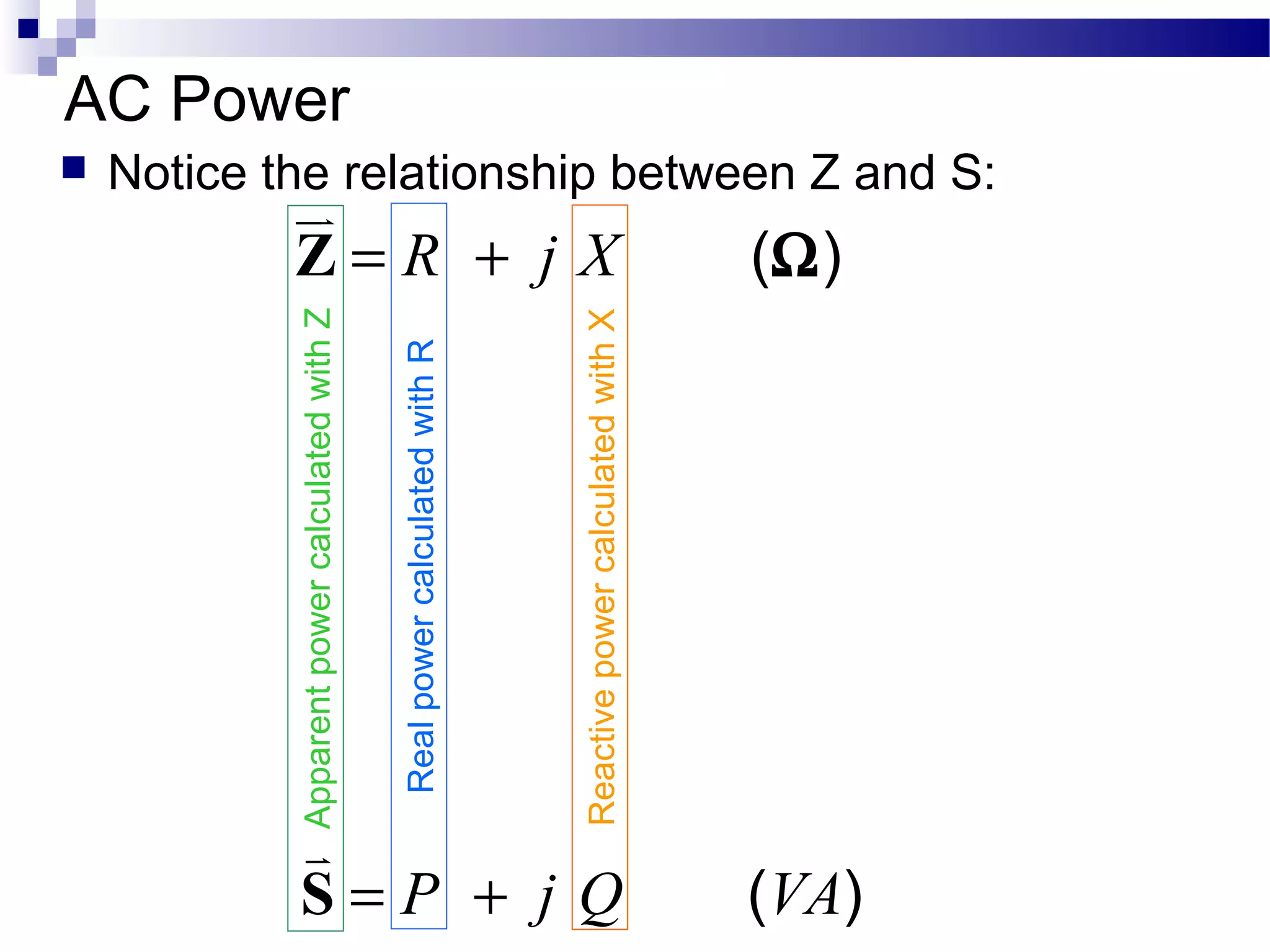
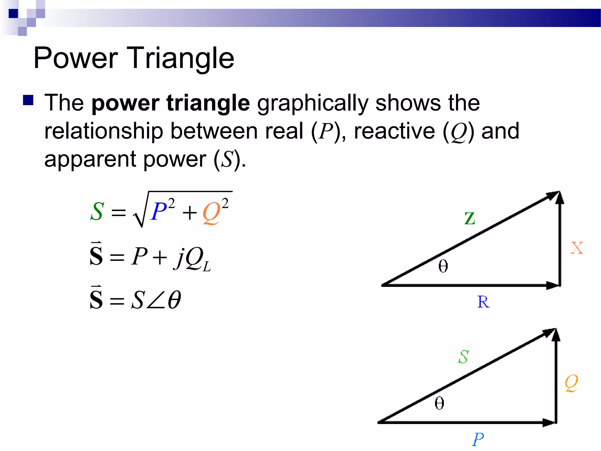
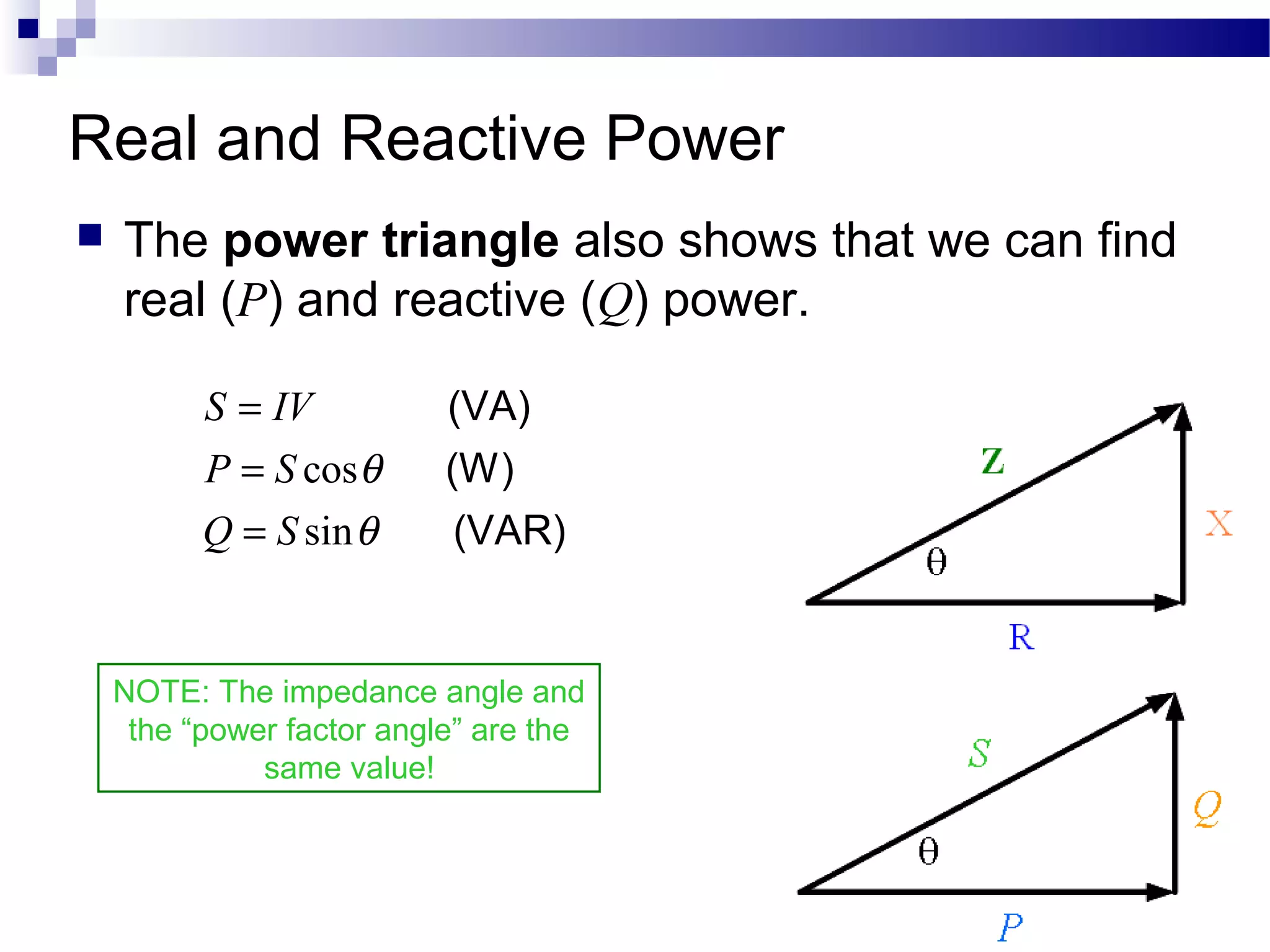
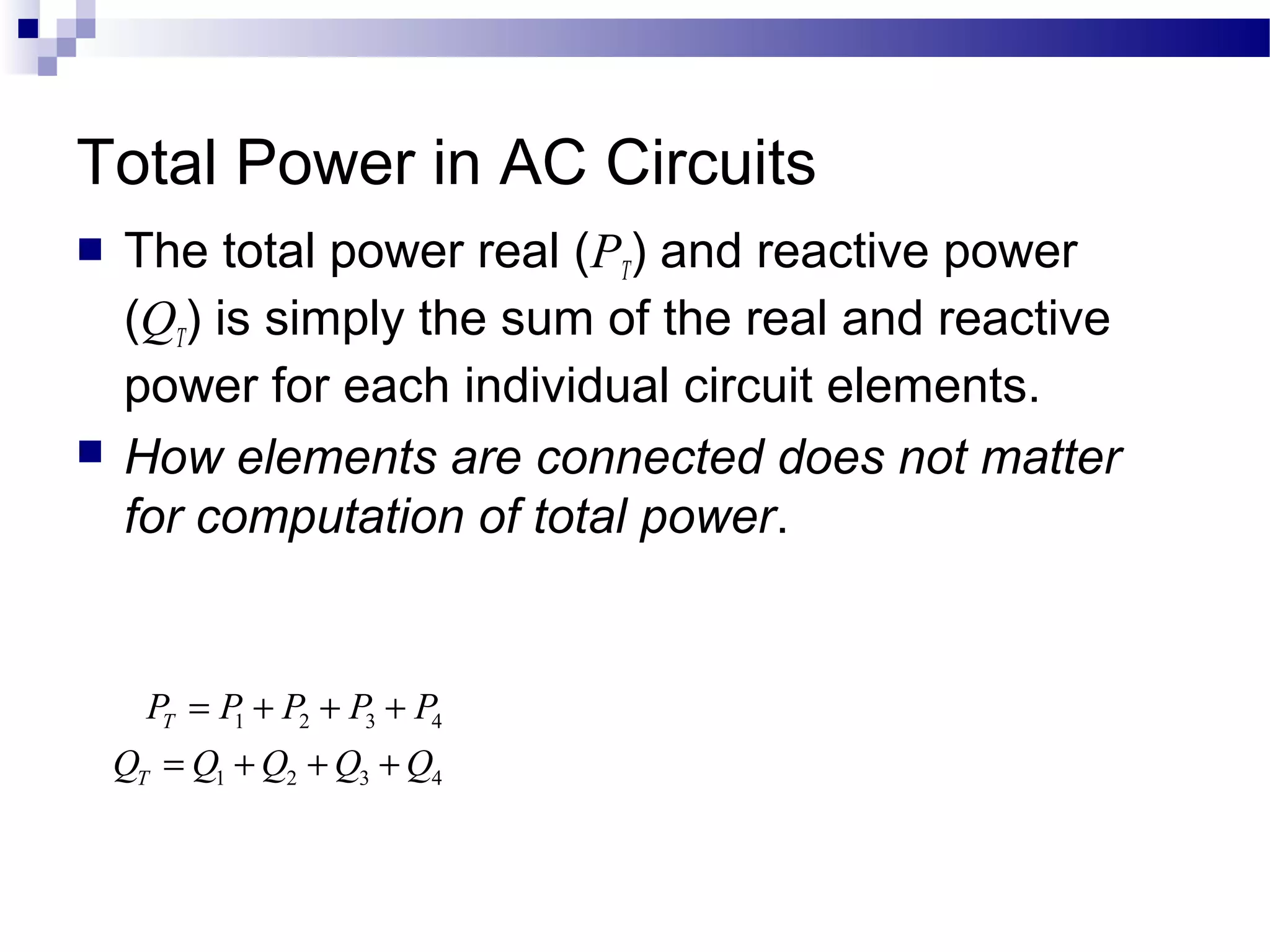
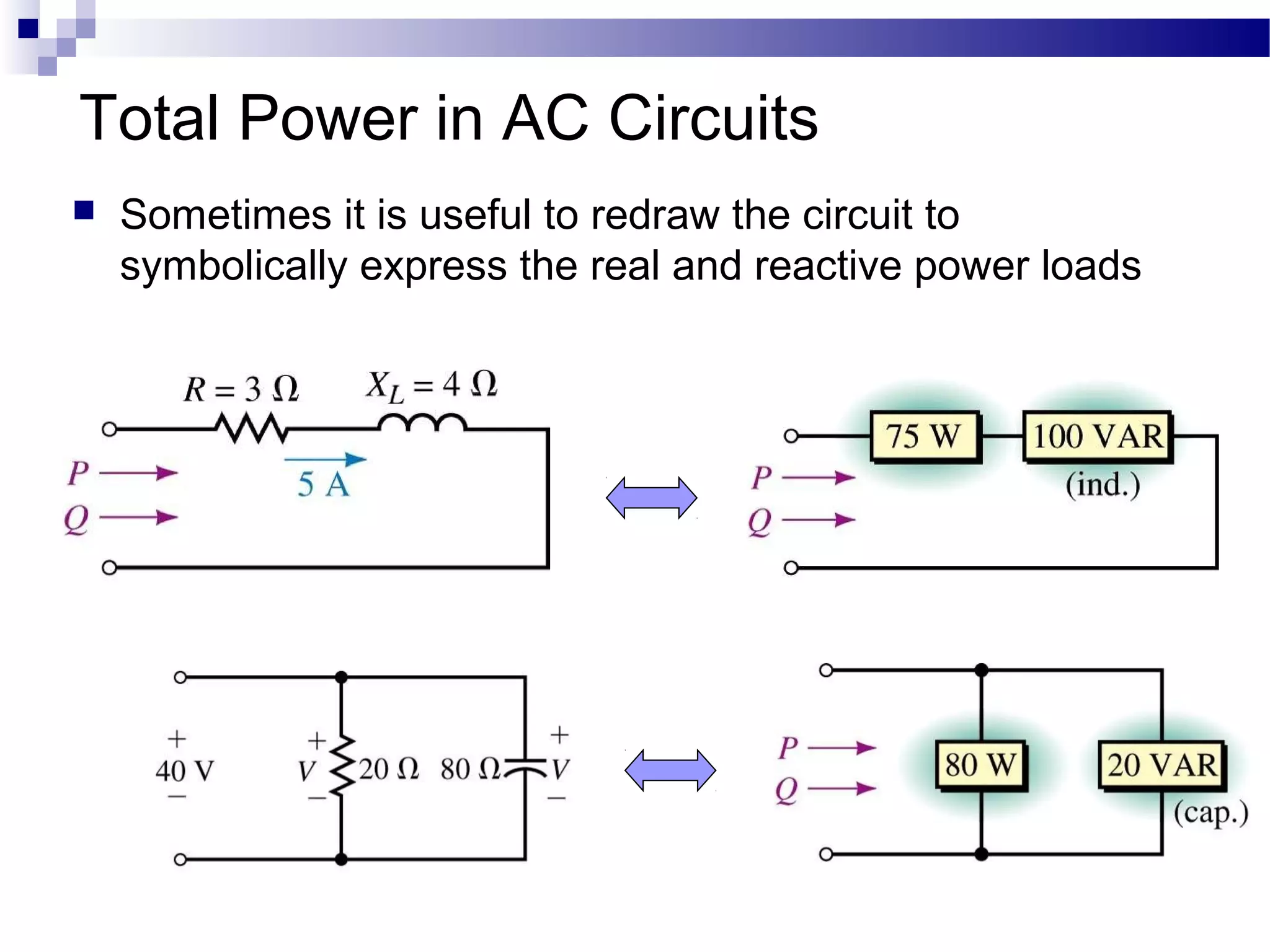
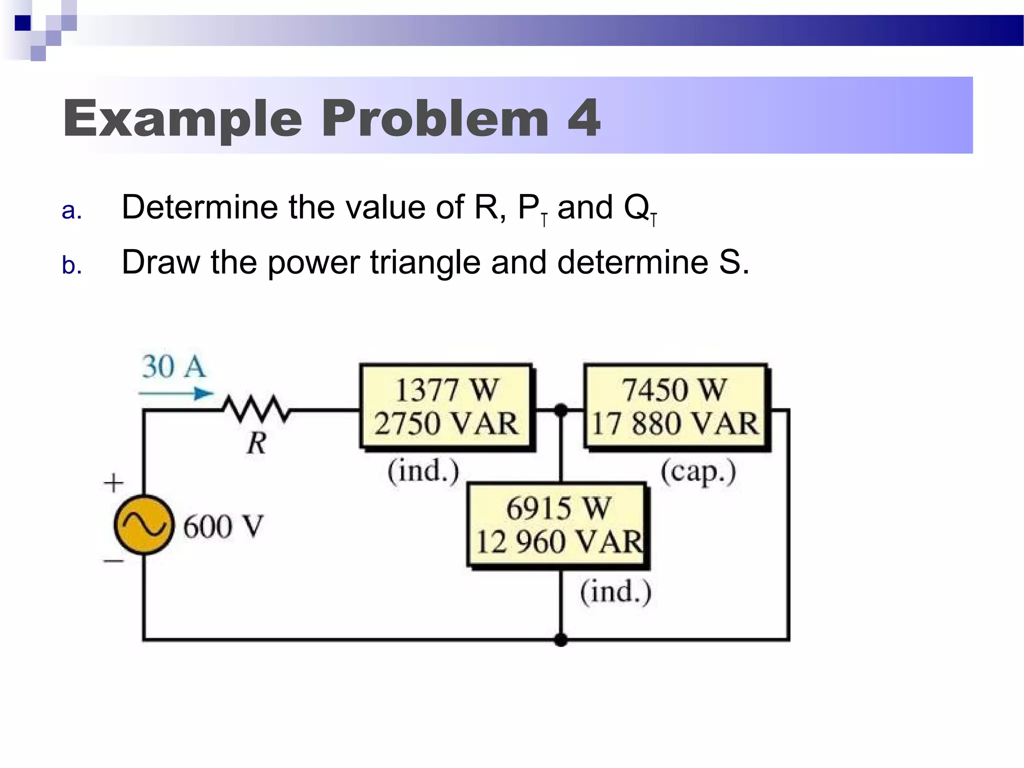
The document discusses AC power concepts including real power, reactive power, and apparent power. It defines real power as power dissipated in resistance, reactive power as power exchanged between reactive components like inductors and capacitors, and apparent power as total power flowing in a circuit. Real power is calculated using resistance, reactive power using reactance, and apparent power using impedance. A power triangle is used to show the relationships between real, reactive, and apparent power components of AC power. Several examples are provided to demonstrate calculating power values in AC circuits.

![AC Real (Active) Power (P)
The Active power is the power that is dissipated
in the resistance of the load.
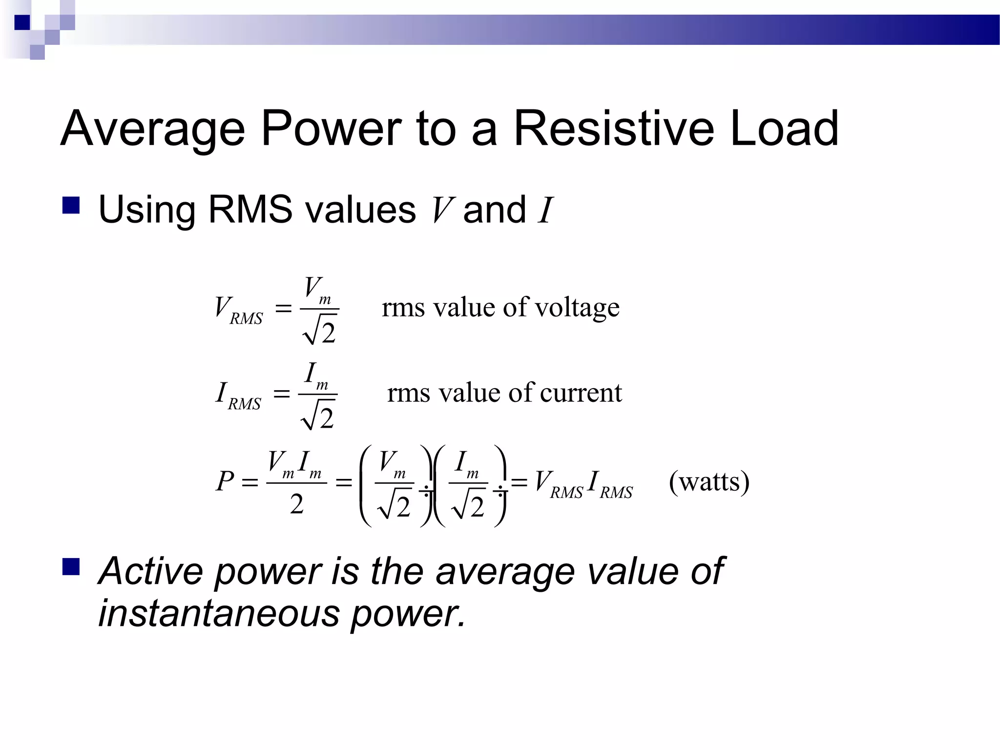
It uses the same formula used for DC (V & I are
the magnitudes, not the phasors):
2
2
[watts, W]P I R
V
R
= =
WARNING! #1 mistake with AC power calculations!
The Voltage in the above equation is the Voltage drop across the resistor, not
across the entire circuit!
CAUTION!
REAL value of resistance (R) is used in REAL power calculations, not
IMPEDANCE (Z)!](https://image.slidesharecdn.com/ee301lesson25acpowerandpwrtriangle-180607071528/75/Ee301-lesson-25-ac-power-and-pwr-triangle-4-2048.jpg)
![AC Imaginary (Reactive) Power (Q)
The reactive power is the power that is exchanged
between reactive components (inductors and capacitors)
The formulas look similar to those used by the active
power, but use reactance instead of resistances.
Units: Volts-Amps-Reactive (VAR)
Q is negative for a capacitor by convention and positive
for inductor.
Just like X is negative for a capacitor! (-Xcj)
2
2
[VAR]Q I X
X
V
= =
WARNING! #1 mistake with AC power calculations!
The Voltage in the above equation is the Voltage drop across the reactance,
not across the entire circuit!](https://image.slidesharecdn.com/ee301lesson25acpowerandpwrtriangle-180607071528/75/Ee301-lesson-25-ac-power-and-pwr-triangle-5-2048.jpg)
![AC Apparent Power (S)
The apparent power is the power that is
“appears” to flow to the load.
The magnitude of apparent power can be
calculated using similar formulas to those for
active or reactive power:
Units: Volts-Amps (VA)
V & I are the magnitudes, not the phasors
2
2
[VA]
V
S VI I Z
Z
= = =](https://image.slidesharecdn.com/ee301lesson25acpowerandpwrtriangle-180607071528/75/Ee301-lesson-25-ac-power-and-pwr-triangle-6-2048.jpg)