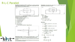
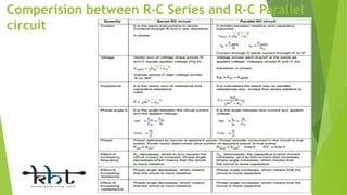
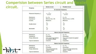
Content
 Alternating current - terms & definitions – vector diagrams.
 Series resonance circuit
 R-L, R-C and R-L-C parallel circuits
 Comperision between R-C Series and R-C Parallel circuit
 Comperision between Series circuit and Parallel circuit.
Introduction
 An alternating current (AC) circuit is one in which
the direction and amplitude of the current flow
change at regular intervals.
 The current in this type of circuit is supplied from
an AC voltage source.
 The polarity of an AC source changes at regular
intervals resulting in a reversal of the circuit current
flow.
 Alternating current usually changes in both value and
direction.
 The current increases from zero to some maximum
value, and then drops back to zero as it flows in one
direction.
 This same pattern is then repeated as it flows in the
opposite direction.
The Sine wave
 The shape of the voltage wave-form generated by a coil rotating in a
magnetic field is called a sine wave.
 The generated sine wave voltage varies in both voltage value and polarity.
 The sine wave is the most basic and widely used AC wave-form.
 The standard AC generator (alternator) produces a voltage of sine wave-
form.
Cycle
 One cycle is one complete wave of alternating voltage or current. During the
generation of one cycle of output voltage, there are two changes or alternations
in the polarity of the voltage.
 These equal but opposite halves of a complete cycle are referred to as
alternations.
 The terms positive and negative are used to distinguish one alternation from the
other.
Time Period
 The time required to produce one complete cycle is called the period of
the wave-form.
 it takes 0.25 seconds to complete one cycle.
 Therefore, the period (T) of that wave-form is 0.25 seconds.
Frequency
 The frequency of an AC sine wave is the number of cycles produced per second.
 The SI unit of frequency is the hertz (Hz).
 For example, the 240V AC at your home has a frequency of 50 Hz.
Instantaneous
 The value of an alternating quantity at any particular instant is called instantaneous
value.
 The instantaneous values of a sine wave voltage is shown diagram. It is 3.1 volts at
1μs, 7.07 V at 2.5μs, 10V at 5μs, 0V at 10μs, 3.1 volt at 11 μs and so on.
Peak Value or Maximum value
 Each alternation of the sine wave is made up of a number of instantaneous values.
 These values are plotted at various heights above and below the horizontal line to
form a continuous wave-form.
Effective Value or RMS Value
 The effective value of an alternating current is that value which will
produce the same heating effect as a specific value of a steady direct
current.
 Another name for the effective value of an alternating current or
voltage is the root mean square (rms) value.
 A simple equation for calculating the effective value of sine wave is:
for voltage, V = 0.707 Vm for current, I = 0.707 Im
Avarage Value
 It is sometimes useful to know the average value for one half cycle.
 If the current is changed at the same rate over the entire half cycle
.the average value would be one half of the maximum value.
 It has been determined that the average value is equal to 0.637
times the maximum value for sine wave-form i.e.
for voltage, Vav = 0.637 Vm for current,Iav = 0.637Im
Form Factor
Peak Factor
Peak Factor is defined as the ratio of maximum value to the
R.M.S value of an alternating quantity.
AC Series Circuits
 R-L Series
 R-C Series
 R-L-C Series
R-L Series
 When resistance and inductance are connected in series, or in the case
of a coil with resistance, the rms current IL is limited by both XL and R
however the current I is the same in XL and R since they are in series,
the voltage drop through R,and its IR voltage drop,are in phase and so
the phase angle is 0°.
 the voltage phasor across the inductor VL is drawn 90° ahead of the
current I in other words leading the current phasor. This is because, as
we know, the current always lags the inductor voltage by 90° in a pure
inductance.
R-C Series
R-L-C Series
AC Parallel Circuits
 R-L Parallel
 R-C Parallel
 R-L-C Parallel
R-L Parallel
R-C Parallel
R-L-C Parallel
Comperision between R-C Series and R-C Parallel
circuit
Comperision between Series circuit and Parallel
circuit.
Thankyou
AC circuit

AC circuit

  • 2.
    Content  Alternating current- terms & definitions – vector diagrams.  Series resonance circuit  R-L, R-C and R-L-C parallel circuits  Comperision between R-C Series and R-C Parallel circuit  Comperision between Series circuit and Parallel circuit.
  • 3.
    Introduction  An alternatingcurrent (AC) circuit is one in which the direction and amplitude of the current flow change at regular intervals.  The current in this type of circuit is supplied from an AC voltage source.  The polarity of an AC source changes at regular intervals resulting in a reversal of the circuit current flow.  Alternating current usually changes in both value and direction.  The current increases from zero to some maximum value, and then drops back to zero as it flows in one direction.  This same pattern is then repeated as it flows in the opposite direction.
  • 4.
    The Sine wave The shape of the voltage wave-form generated by a coil rotating in a magnetic field is called a sine wave.  The generated sine wave voltage varies in both voltage value and polarity.  The sine wave is the most basic and widely used AC wave-form.  The standard AC generator (alternator) produces a voltage of sine wave- form.
  • 5.
    Cycle  One cycleis one complete wave of alternating voltage or current. During the generation of one cycle of output voltage, there are two changes or alternations in the polarity of the voltage.  These equal but opposite halves of a complete cycle are referred to as alternations.  The terms positive and negative are used to distinguish one alternation from the other.
  • 6.
    Time Period  Thetime required to produce one complete cycle is called the period of the wave-form.  it takes 0.25 seconds to complete one cycle.  Therefore, the period (T) of that wave-form is 0.25 seconds.
  • 7.
    Frequency  The frequencyof an AC sine wave is the number of cycles produced per second.  The SI unit of frequency is the hertz (Hz).  For example, the 240V AC at your home has a frequency of 50 Hz.
  • 8.
    Instantaneous  The valueof an alternating quantity at any particular instant is called instantaneous value.  The instantaneous values of a sine wave voltage is shown diagram. It is 3.1 volts at 1μs, 7.07 V at 2.5μs, 10V at 5μs, 0V at 10μs, 3.1 volt at 11 μs and so on.
  • 9.
    Peak Value orMaximum value  Each alternation of the sine wave is made up of a number of instantaneous values.  These values are plotted at various heights above and below the horizontal line to form a continuous wave-form.
  • 10.
    Effective Value orRMS Value  The effective value of an alternating current is that value which will produce the same heating effect as a specific value of a steady direct current.  Another name for the effective value of an alternating current or voltage is the root mean square (rms) value.  A simple equation for calculating the effective value of sine wave is: for voltage, V = 0.707 Vm for current, I = 0.707 Im
  • 11.
    Avarage Value  Itis sometimes useful to know the average value for one half cycle.  If the current is changed at the same rate over the entire half cycle .the average value would be one half of the maximum value.  It has been determined that the average value is equal to 0.637 times the maximum value for sine wave-form i.e. for voltage, Vav = 0.637 Vm for current,Iav = 0.637Im
  • 12.
    Form Factor Peak Factor PeakFactor is defined as the ratio of maximum value to the R.M.S value of an alternating quantity.
  • 13.
    AC Series Circuits R-L Series  R-C Series  R-L-C Series
  • 14.
    R-L Series  Whenresistance and inductance are connected in series, or in the case of a coil with resistance, the rms current IL is limited by both XL and R however the current I is the same in XL and R since they are in series, the voltage drop through R,and its IR voltage drop,are in phase and so the phase angle is 0°.  the voltage phasor across the inductor VL is drawn 90° ahead of the current I in other words leading the current phasor. This is because, as we know, the current always lags the inductor voltage by 90° in a pure inductance.
  • 16.
  • 18.
  • 19.
    AC Parallel Circuits R-L Parallel  R-C Parallel  R-L-C Parallel
  • 20.
  • 21.
  • 22.
  • 23.
    Comperision between R-CSeries and R-C Parallel circuit
  • 24.
    Comperision between Seriescircuit and Parallel circuit.
  • 25.