Downloaded 199 times


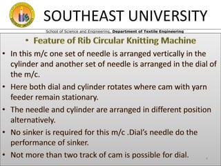


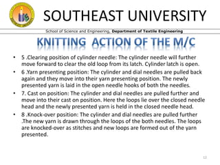


This document discusses a circular knitting machine used to produce rib structures. It describes the basic components of the machine, including the creel, feeder, dial, needles, cam, cylinder, and fabric spreader. It explains the 8 steps of the knitting process, from the rest position to the knock-over position where new loops are formed. It also includes diagrams of the motor to cylinder gearing and calculations for production rates based on machine specifications. In summary, the document provides an overview of a rib circular knitting machine, outlines its key parts and operating principles, and gives examples of production calculations.