Downloaded 53 times


![Verilog code
module ALU(input [3:0]ALUOP,input [1:0]A,B,
output reg [1:0]R,output reg C);
always@(*)begin
case(ALUOP)
4'b0000: {C,R}=(A+B);
4'b0001: {C,R}=(A-B);
4'b0010: R=(A&B);
4'b0011: R=~(A&B);
4'b0100: R=(A|B);
4'b0101: R=~(A|B);
4'b0110: R=(A^B);
4'b0111: R=~(A^B);
4'b1000,4'b1001:R=~(A);
default: R=4'bxxxx;
endcase
end
endmodule
Slide 24](https://image.slidesharecdn.com/2bitalu-170810123051/85/2-bit-alu-24-320.jpg)
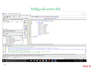
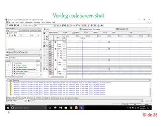
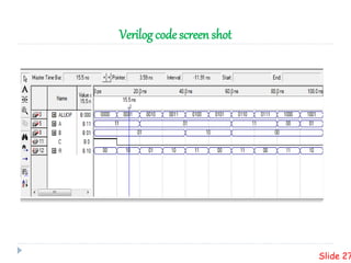


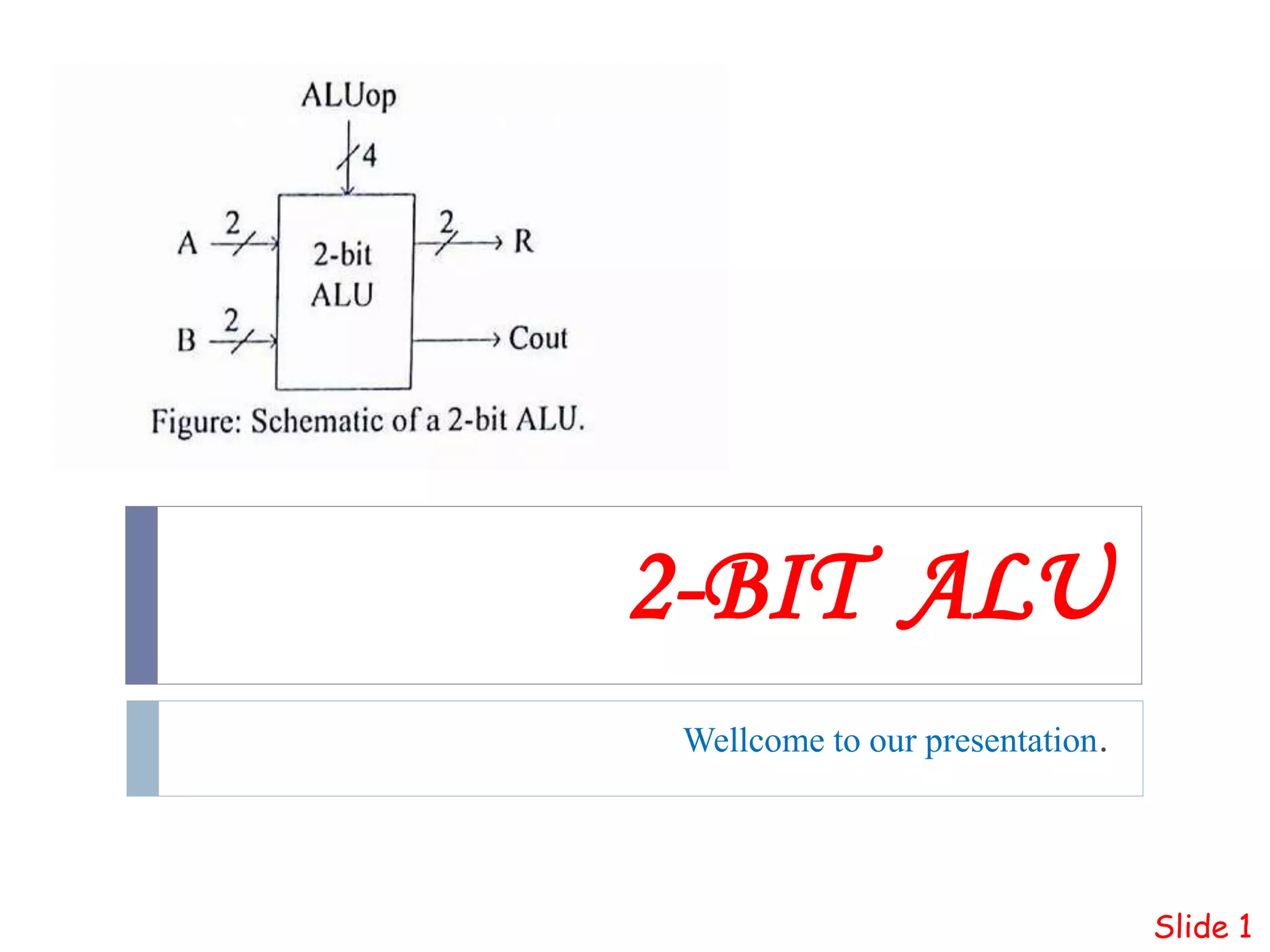
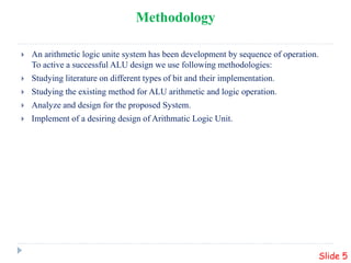
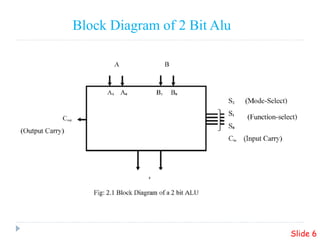
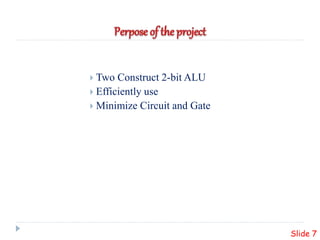
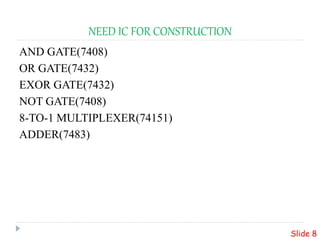
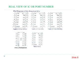
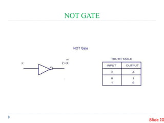
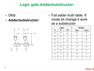
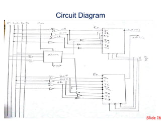
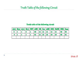
This presentation summarizes the design of a 2-bit arithmetic logic unit (ALU). It includes the group members, an overview of what an ALU is and its methodology. It shows the block diagram and needed integrated circuits. The circuit diagram, truth table, and how it works are described. Advantages like minimum delay and disadvantages like limited output are discussed. Verilog code for the ALU is also included.