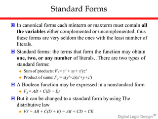
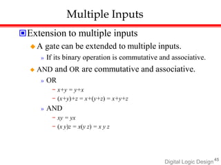
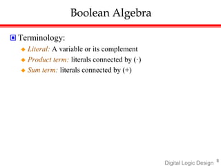
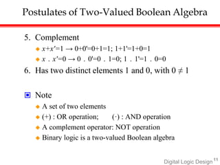
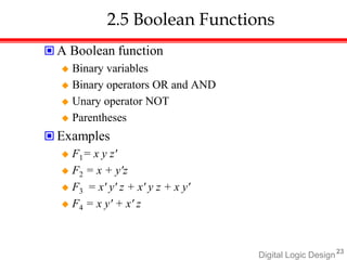
Digital Logic Design introduces Boolean algebra and logic gates. Boolean algebra defines rules for binary operations like AND, OR, and NOT using a set of 0s and 1s. Some key concepts covered include:
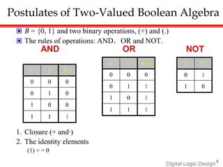
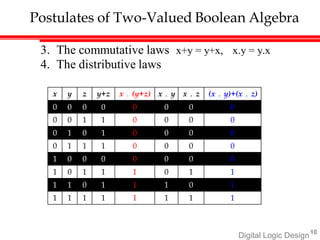
- Boolean algebra postulates that define closure, identity elements, commutative/distributive laws, and complements.
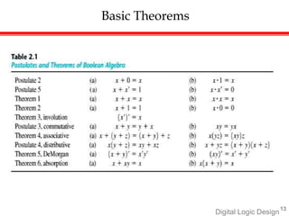
- Basic theorems like absorption and De Morgan's theorem that are derived from the postulates.
- Boolean functions that use binary variables with AND, OR, and NOT operations to represent logic expressions.
![Digital Logic Design28
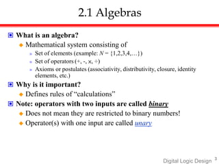
Examples
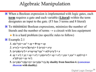
Example 2.2
F1' = (x'yz' + x'y'z)' = (x'yz')' (x'y'z)' = (x+y'+z) (x+y+z')
F2' = [x(y'z'+yz)]' = x' + (y'z'+yz)' = x' + (y'z')' (yz)‘
= x' + (y+z) (y'+z')
= x' + yz‘+y'z
Example 2.3: a simpler procedure
Take the dual of the function and complement each literal
1. F1 = x'yz' + x'y'z.
The dual of F1 is (x'+y+z') (x'+y'+z).
Complement each literal: (x+y'+z)(x+y+z') = F1'
2. F2 = x(y' z' + yz).
The dual of F2 is x+(y'+z') (y+z).
Complement each literal: x'+(y+z)(y' +z') = F2'](https://image.slidesharecdn.com/m3ppt22esc143-221219141126-12e08201/85/M3-PPT-22ESC143-docx-29-320.jpg)